
Inspection and Test Plan for Method Statement: Installation of Internal Window Roller Blinds and Automated Motorized Curtain Tracking Systems
AI-assisted inspection and test plan connected to a method statement, with PDF and Excel export.
More than a static template
Unlike a downloadable Word or PDF template, this ITP is an AI-assisted editable starting point directly connected to its method statement. Every inspection activity, hold point, and acceptance criterion is structured and ready to adapt to your project.
- AI-assisted customization — Tailor inspection activities and acceptance criteria to your specific project scope.
- Linked method statement — This ITP is connected to the corresponding method statement describing the work sequence.
- Multiple export formats — Download as a formatted PDF or editable Excel spreadsheet.
- Editable starting point, not a final document — Review and verify all content against your project specifications and standards before use.
What you can customize
When you save this ITP to your account, every inspection row becomes editable. You can add, remove, or modify:
- Inspection activity — Description of what is being inspected.
- Inspection type — Hold point (H), Witness point (W), Review (R), or Monitor (M).
- Responsibility — Contractor, subcontractor, engineer, or client.
- Frequency — How often the inspection occurs.
- Acceptance criteria — Referenced standard or specification requirement.
- Records — Forms, test reports, or checklists required as evidence.
Why this ITP is used
To control quality and verify compliance with standards, drawings, and OEM requirements through defined inspections and tests.
Who uses this inspection and test plan
Contractor supervisors, QA/QC inspectors, electricians, commissioning engineers, and the Client/Consultant.
When this ITP is prepared and submitted
From pre-installation survey through fixings, electrical testing, programming, integration, and final acceptance.
Who receives or approves this ITP
Client/Consultant for review and approval prior to works.
Inspection scope
Materials, surveys, set-out, anchors, electrical testing, functional checks, programming, integration, safety devices, and documentation.
Typical hold, witness, and review points
First-off survey (Hold), Limit setting (Witness), Final inspection (Hold), Anchor proof tests (Witness).
Typical inspection records
Survey sheets, fixing/torque logs, pull-test reports, electrical test sheets, commissioning certificates, integration reports, safety checklists, and handover dossiers.
Important approval note
This ITP is an AI-assisted editable starting point, not a pre-approved document. Before use on any project, all inspection activities, hold points, and acceptance criteria must be reviewed and approved by the relevant parties (superintendent, principal contractor, or client representative) in accordance with your contract and project quality plan.
Always verify acceptance criteria against your applicable drawings, specifications, and regulatory requirements. Hold points must be confirmed with the relevant authority before work proceeds past that point.
Inspection and test plan
| Activity | Inspection / Test | Acceptance Criteria | Responsibility | Record |
|---|---|---|---|---|
| Material delivery inspection | Verify model numbers, finishes, certificates (BS 5867, OEM docs) | Materials match approved submittals; certificates present and valid | QA/QC Inspector | Material inspection report |
| Pre-install survey (Hold Point) | Recess W/H/D at three points; level/plumb | Within stated tolerances; clashes resolved via RFI if outside | Site Supervisor / Consultant | Survey sheet; Consultant sign-off |
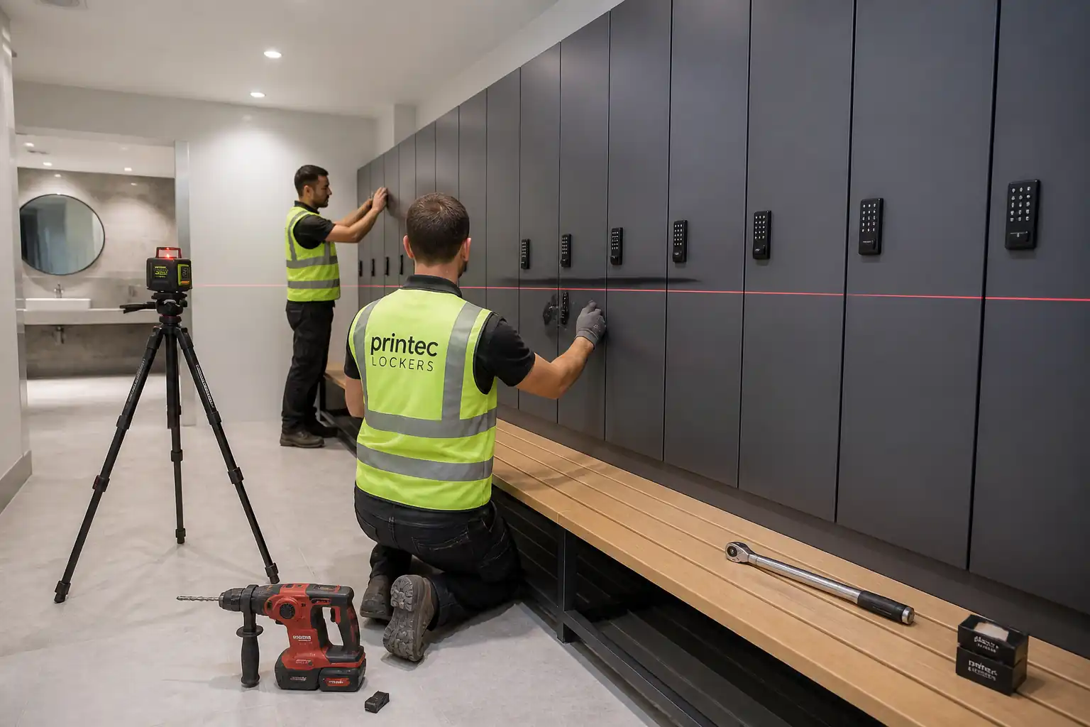
| Set-out verification | Laser level and spacing check | Level ±2 mm; spacing/edge distances per OEM/BS 8539 | QA/QC Inspector | Set-out checklist |
| Anchor installation and torque | Torque verification with calibrated tool | Within OEM torque range; no substrate failure | Installer / QA/QC | Fixing/torque log |
| Anchor proof test (sample) | Pull-out/proof load per plan | ≥1.5 × design load; no slippage/loosening [Verify] | QA/QC / Consultant (Witness) | Pull-test report |
| Bracket/headbox alignment | Level/line measurements | Within tolerances; secure fix | QA/QC Inspector | Alignment checklist; photos |
| Electrical pre-energization tests | Continuity, polarity; IR for 230 V circuits | Meets BS 7671/IEC 60364; IR ≥1 MΩ (230 V); correct polarity/earth | Electrician | Electrical test sheet |
| Mechanical installation check | Free travel; no binding; end-stops present | Smooth movement; no interference | Site Supervisor | Installation inspection sheet |
| Limit setting calibration (Witness) | Measure top/bottom limits over 3 cycles | ±5 mm accuracy; ±2 mm repeatability | Commissioning Engineer / Consultant | Commissioning certificate |
| Remote pairing and group/scene tests | Range and synchronization | Range ≥10 m LOS [Verify]; group sync within 1 s | Commissioning Engineer | Integration test report |
| BMS/third-party integration | Point-to-point; fail-safe; address mapping | All points proven; correct logic; safe state on power loss | Commissioning Engineer / BMS Integrator | BMS I/O test sheets |
| Fabric tracking/alignment | Edge deviation and rub check | Edge deviation ≤2 mm; no rubbing or fraying | Installer / QA/QC | Alignment log; photos |
| Child-safety device verification | Measurement & device function check | Compliant with BS EN 13120 (e.g., controls ≥1500 mm AFFL or safety device fitted) [Verify] | QA/QC / Supervisor | Safety checklist |
| Final inspection and snag closure (Hold Point) | Random cycle tests; aesthetic inspection | Zero critical snags; minor snags logged and closed | Client/Consultant | Final inspection certificate; snag list |
| Handover documentation | Completeness check | O&M manuals, warranties, as-builts, logs provided | Project Manager | Handover dossier |
This table is a read-only public reference. Download the PDF or Excel version, or customize this ITP to edit it for your project.
Frequently asked questions
Related method statement
This Inspection and Test Plan is associated with the Method Statement: Installation of Internal Window Roller Blinds and Automated Motorized Curtain Tracking Systems method statement, which describes the step-by-step construction sequence, resources, materials, equipment, safety controls, and environmental controls for this activity.
View the Method Statement: Installation of Internal Window Roller Blinds and Automated Motorized Curtain Tracking Systems method statement →Continue with related inspection, method statement, article, and checklist resources.