Method Statement – Firestopping of Cable Tray Penetrations Through Fire-Rated Walls (Intumescent Pillows or Board Systems) – Method Statement
AI-assisted method statement with matching ITP, PDF download, and Excel export.
More than a static template
Unlike a downloadable Word or PDF template, this method statement is an AI-assisted editable starting point connected directly to a matching Inspection and Test Plan. Every section is structured, project-adaptable, and ready to export.
- AI-assisted drafting — Customize every section with AI for your specific project scope.
- Linked ITP — A matching inspection and test plan is generated alongside the method statement.
- Multiple export formats — Download as a formatted PDF or editable Excel spreadsheet.
- Editable starting point, not a final document — Review, verify, and adjust all content against your project requirements before use.
Static template vs. Quollnet workflow
| Feature | Static template | Quollnet |
|---|---|---|
| Project-specific content | Manual fill-in required | AI-assisted customization |
| Linked ITP | Separate document, no link | Matching ITP included |
| Export formats | Usually PDF only | PDF and Excel |
| Structured sections | Free-form layout | 13 standardized sections |
| Saved to your account | Local file only | Cloud-saved, reusable |
| Content accuracy | You verify everything | AI-assisted, you still verify |
| Cost | Often free but time-intensive | Free to customize and download |
What you can customize
When you save this method statement to your account, every section becomes editable. The following 13 sections are included:
- Scope — Defines the activity and its boundaries.
- References — Standards, specifications, and drawings.
- Responsibilities — Roles and accountabilities.
- Resources — Labour, plant, and equipment summary.
- Materials — Materials and compliance requirements.
- Equipment — Tools and equipment details.
- Prerequisites — Hold points and pre-conditions.
- Method sequence — Step-by-step construction sequence.
- Safety controls — HSE risk controls and PPE.
- Environmental controls — Environmental mitigation measures.
- QA/QC — Quality inspection and test requirements.
- ITP — Inspection and Test Plan table (has its own page).
- Attachments — Referenced drawings and documentation.
Why this method statement is used
This method statement is used to define and communicate the approved procedure for carrying out method statement – firestopping of cable tray penetrations through fire-rated walls (intumescent pillows or board systems) on site. It ensures the work is planned in advance, the correct resources and controls are in place, and all personnel understand responsibilities, sequence, quality requirements, and safety controls before work begins. It aligns site execution with the documented scope and acceptance expectations.
Who uses this method statement
This method statement is used by contractors, site supervisors, project engineers, QA/QC engineers, HSE officers, consultants, and client representatives. It serves as a shared reference for planning, execution, supervision, inspection, and approval of the activity on site.
When it is prepared and submitted
The method statement is prepared before the work activity starts and submitted as part of the pre-construction documentation package for review and approval.
Who reviews or approves it
The method statement is usually submitted to the client representative, consultant, resident engineer, or project management consultant for review and approval before the work commences.
Important approval note
This method statement is an AI-assisted editable starting point, not a pre-approved document. Before use on any project, all content must be reviewed and approved by the relevant parties (superintendent, principal contractor, or client representative) in accordance with your contract and project quality plan.
For example: if your specification requires a departure from a referenced standard, that departure must be documented and approved separately — this method statement will not capture that automatically. Always verify against your applicable drawings, specifications, and regulatory requirements.
Method statement content
Scope
Description
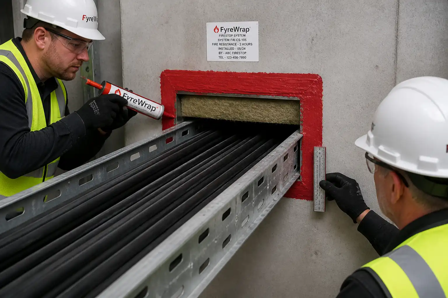
This method covers the installation of firestopping for cable tray penetrations through fire-rated walls using either:
- Re-enterable intumescent pillow systems; or
- Coated mineral wool board (ablative) systems with sealant.
Work includes:
- Verification of wall construction and fire-resistance rating (FRR/FRL) and selection of a tested firestop system to match the assembly and services.
- Preparation of penetrations, cable tray separation so supports do not bridge the fire barrier, and sealing around cables and tray per the tested listing.
- Installation, inspection (including defined HOLD point prior to closure), labeling, documentation, and as-built updates.
Objectives
- Re-establish the wall’s fire resistance (F rating) and smoke/leakage performance (T/S/L ratings where required) at penetrations.
- Prevent mechanical bridging of the fire barrier by cable trays or supports while maintaining bonding/earthing continuity by an electrical jumper, not by the tray.
- Allow controlled future cable additions for pillow systems (re-enterable) without compromising the rating.
Exclusions
- Firestopping for plastic pipes, expansion joints, or bus-ducts not contained in trays (covered by separate methods).
- Wall reconstruction where penetrations exceed tested system limits.
Interfaces
- Electrical installation, bonding/earthing, wall/partition trades, fire alarm, and building control authority inspections.
References
| Document Type | Reference / Number | Revision | Notes |
|---|---|---|---|
| Standard | ASTM E814 / UL 1479 – Fire Tests of Penetration Firestop Systems [Verify applicability per project location] | Primary firestop system test standard for through-penetrations. | |
| Standard | BS EN 1366-3 – Fire resistance tests for service installations – Part 3: Penetration seals [Verify applicability] | European equivalent for penetration seals. | |
| Standard | EN 13501-2 – Fire classification of construction products and building elements – Part 2 [Verify applicability] | Classification criteria for fire resistance (e.g., EI). | |
| Code/Guide | IBC/IFC or local Building/Fire Code referencing tested/approved firestop systems [Verify per project jurisdiction] | Regulatory basis for using listed systems and labeling. | |
| Electrical Code | NFPA 70 (NEC) / BS 7671 – Electrical bonding/earthing, cable tray installation clearances [Verify applicability] | For tray termination, bonding jumpers, and conductor routing. | |
| Approval/Listing | UL Fire Resistance Directory systems (e.g., W-L, C-AJ series) / ETA/CE marked systems [Verify exact listing] | Select and install strictly per the tested system details. | |
| Quality | ISO 9001 (contractor/manufacturer), ISO 14001 (environment) [Verify applicability] | Quality and environmental management framework. | |
| Manufacturer Data | Manufacturer’s current Technical Data Sheets (TDS), Safety Data Sheets (SDS), and Installation Instructions | Follow shelf life, storage, application, cure, WFT/DFT, compression/packing depth. |
Responsibilities
| Role | Responsibility | Name / Party |
|---|---|---|
| PM | Project Manager | Contractor |
| CM/SE | Construction Manager / Site Engineer | Contractor |
| QA/QC | QA/QC Engineer | Contractor |
| HSE | HSE Officer | Contractor |
| Electrical | Electrical Supervisor | Contractor |
| Installer | Certified Firestop Installer | Specialist Subcontractor |
| Engineer | Consultant/Engineer / Authority Having Jurisdiction (AHJ) | Client/Engineer |
Resources
| Resource Type | Description | Quantity | Remarks |
|---|---|---|---|
| Manpower | Certified firestop installers | 2–4 | |
| Manpower | Electrician + mate (tray termination, bonding) | 2 | |
| Manpower | QC inspector | 1 | |
| Manpower | HSE officer (shared) | 1 (shared) |
Materials
| Material | Specification / Grade | Quantity | Remarks |
|---|---|---|---|
| Intumescent Firestop Pillows | Listed to ASTM E814/UL 1479 or EN 1366-3 [Verify per project] | Use only as per matching tested system | |
| Coated Mineral Wool Board System | Mineral wool board 60–150 kg/m³, thickness typically 50 mm with ablative coating [Verify per tested system] | Edge-sealed per listing | |
| Intumescent/Acrylic Firestop Sealant (or Silicone where specified) | Listed sealant compatible with system; bead/fillet 10–20 mm typical [Verify] | ||
| Mineral Wool (Stone Wool) Packing | Density 64–128 kg/m³, packing depth per listing (typically 100 mm) [Verify] | ||
| Retention Mesh / Angle / Hanger System | Galvanized steel mesh/angles; corrosion-resistant | ||
| Cable Tray Termination Hardware | Tray couplers, end plates, fasteners as per tray manufacturer | ||
| Bonding/Earthing Jumper | Sized per NFPA 70/BS 7671; route through sealed penetration or adjacent listed path [Verify] | ||
| Firestop Identification Labels/Tags | Include system ID, rating, installer, date, re-entry notes |
Equipment
| Equipment | Capacity / Type | Quantity | Inspection Required |
|---|---|---|---|
| Drills + Dust Extraction (HEPA) | 1–2 | ||
| Hand tools/Knives/Shears | As required | ||
| Measuring tools (tape, calipers, depth gauge, WFT gauge) | Set | ||
| Mobile scaffold/tower, podium ladder | As needed | ||
| Caulking guns, brushes, trowels | Sets | ||
| Anchors, threaded rod, channels/trapeze kits | As needed |
Prerequisites
- Approved shop drawings and selection of a tested firestop system (UL/ETA) matching: wall type/thickness, FRR/FRL, cable tray type/size, cable mix, annular spaces, and required ratings (F/T, or EI/S) [Verify per project specifications].
- Method Statement and ITP approved by Consultant/Engineer.
- Confirm wall construction completed and cured; opening sized within the limits of the tested system.
- Utilities/Services: Assess need for de-energization or LO/TO of affected circuits; coordinate fire alarm impairment and hot works permits if applicable [Verify per project HSE plan and local regulations].
- Access and temporary protection arranged; exclusion zone established.
- Materials within shelf life; SDS available; installers certified by firestop manufacturer where required.
- Calibration of measurement devices; inspection checklists prepared.
- Pre-work briefing and risk assessment communicated to crew.
- Hold Point: Pre-close inspection scheduled and notified to Consultant/Engineer.
Method Sequence
| Step | Activity | Description | Responsibility | Inspection / Hold Point |
|---|---|---|---|---|
| 1 | Pre-Inspection and Identification | Verify wall rating/type; confirm tested system ID (e.g., UL C-AJ/W-L series) matches services and wall. Measure opening and cable tray dimensions; record annular space. | QA/QC + Installer | Check design vs site |
| 2 | Isolate and Prepare Work Area | Install barriers/signage; protect finishes. If required, de-energize and lockout/tagout affected circuits. Remove debris and clean opening edges; ensure dry, dust-free substrate. | HSE + Electrical + Installer | Area readiness |
| 3 | Ensure Tray Support Separation (No Bridging) | Terminate cable tray each side of wall; provide independent supports within 300–600 mm from wall face [Verify per tray mfr/spec]. Maintain 25–50 mm gap from tray end to wall face [Verify]. No mechanical members to pass continuously through the wall. Install bonding/earthing jumper sized per code across the discontinuity; route through the same or adjacent listed penetration. | Electrical Supervisor + Installer | Visual + measurements |
| 4 | Opening Conditioning | Square and dress edges without over-enlarging. For board systems, fit temporary support/retention as per listing. Verify annular space limits and packing depth from listing. | Installer | Dimensional check |
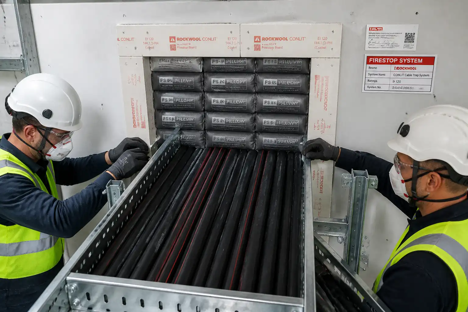
| 5A | Install Intumescent Pillow System (Option A) | Insert pillows tightly to achieve required compression (typically 25–33% overall compression) and required thickness/packing depth per listing. Orient seams as specified. Fit retention mesh/angles if required by system. Seal perimeter and minor gaps with listed intumescent sealant (typical fillet 10–20 mm). | Certified Firestop Installer | In-process |
| 5B | Install Coated Board System (Option B) | Cut mineral wool board to fit snugly around tray, oversize by 5–10 mm for tight friction fit. Pack remaining annulus with mineral wool to depth specified (typically 100 mm). Apply ablative coating to both sides to WFT sufficient to achieve DFT per TDS (e.g., WFT 1.5–2.5 mm for DFT 1.0–1.8 mm) [Verify]. Form neat perimeter seals. | Certified Firestop Installer | In-process |
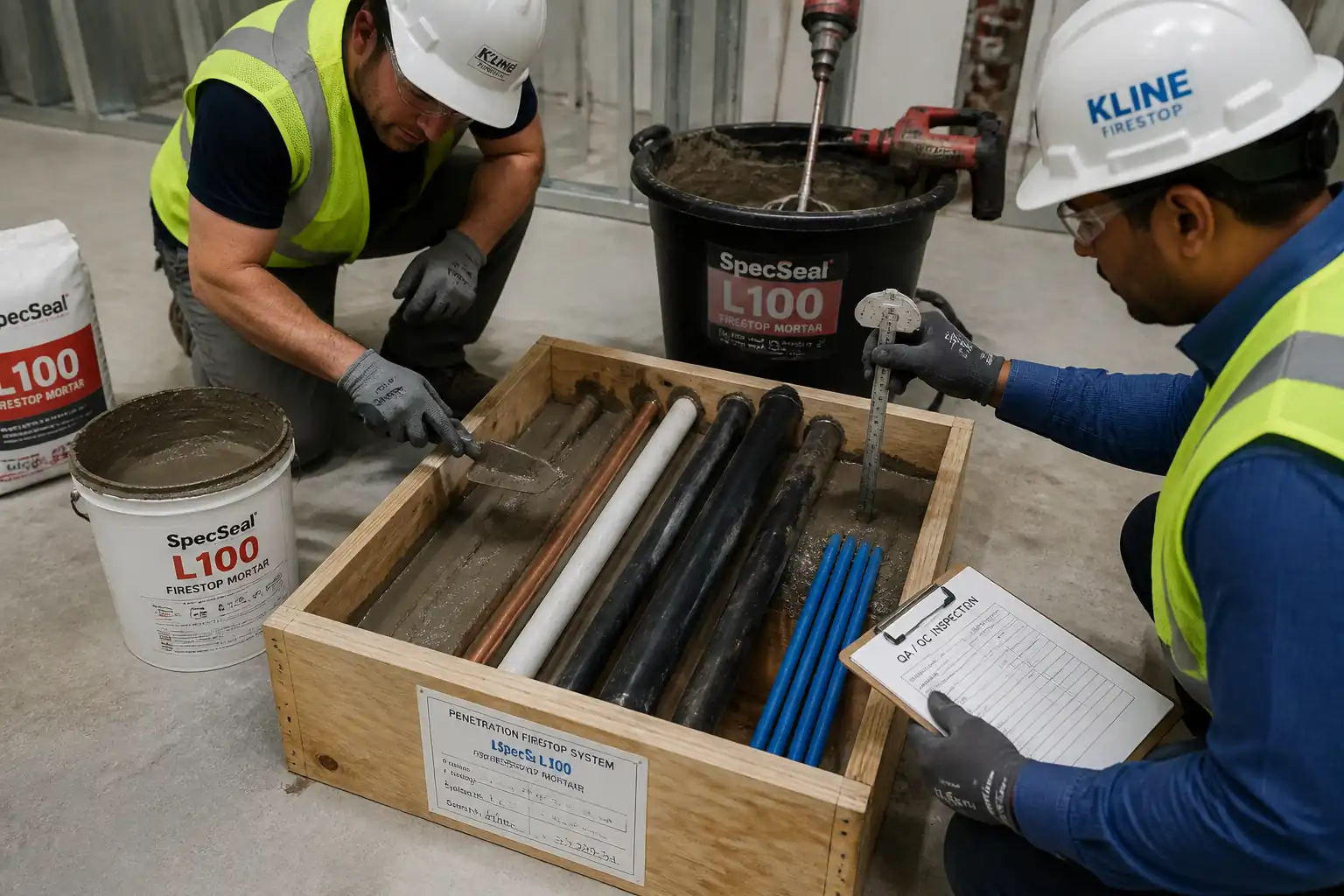
| 6 | Hold Point – Pre-Closure Inspection | Request inspection before final closure/labeling. Expose all faces for viewing. Provide system data, measurements, WFT/DFT records, and photos. | QA/QC + Engineer | HOLD |
| 7 | Closure, Finishing, and Labeling | Complete any required sealant fillets, install retention covers if specified, clean surfaces. Affix permanent label on both sides: system ID, rating, installer, date, re-entry rules. | Installer | Visual |
| 8 | Post-Installation Tests and Handover | Conduct bonding continuity verification if disturbed; restore fire alarm systems; remove PTW/LOTO. Submit as-builts, product data, maintenance instructions, and re-entry procedure for pillow systems. | Electrical + QA/QC | Final |
Health, Safety, and Environmental Controls – Safety
Task-Specific Hazards and Controls
- Hazard: Live electrical exposure from energized cables
- Consequence: Electric shock, burns, arc flash
- Engineering/Procedural Control: LO/TO of affected circuits; confirm absence of voltage with calibrated tester; maintain minimum approach distances; use insulated tools; coordinate with electrical permit
- Required PPE: Insulated gloves where applicable, arc-rated clothing per risk, safety glasses/face shield, dielectric footwear [Verify per project HSE plan and local regulations]
- Collective Preventive Measure: Barriers and lock boxes; signage and controlled access
-
Inspection/Permit/Supervision: Electrical PTW/LOTO, supervisor verification, test records retained
-
Hazard: Working at height for high-level wall penetrations
- Consequence: Falls causing serious injury
- Engineering/Procedural Control: Use inspected mobile tower/podium with guardrails; tie-off if using MEWP; maintain 3-point contact on ladders for short-duration tasks only
- Required PPE: Full body harness with lanyard when required, non-slip footwear, hard hat
- Collective Preventive Measure: Fall protection systems, toe boards, spotter
-
Inspection/Permit/Supervision: Daily equipment inspection tags; Work at Height permit; competent person oversight
-
Hazard: Drilling for tray supports/anchors
- Consequence: Silica dust inhalation, eye injury, noise-induced hearing loss
- Engineering/Procedural Control: HEPA dust extraction; wet suppression if allowed; core bit with depth stop; noise control schedule
- Required PPE: P2/P3 respirator, safety goggles, hearing protection, gloves
- Collective Preventive Measure: Local exhaust ventilation, exclusion zone
-
Inspection/Permit/Supervision: Tool PAT, pre-use checks, dust control plan, noise monitoring if required
-
Hazard: Irritant fibers from mineral wool and chemical exposure from sealants/coatings
- Consequence: Skin/respiratory irritation, dermatitis
- Engineering/Procedural Control: Follow SDS; use low-VOC products where specified; mix/apply in ventilated areas; avoid skin contact; sealed containers
- Required PPE: Nitrile gloves, long sleeves, safety goggles, P2 respirator if airborne fibers present
- Collective Preventive Measure: Ventilation and local extraction; wash stations
-
Inspection/Permit/Supervision: SDS on site; COSHH/chemical handling permit if applicable; HSE walkdowns
-
Hazard: Penetration working in congested risers/shafts (confined-like conditions)
- Consequence: Restricted egress, poor ventilation, entrapment
- Engineering/Procedural Control: Permit to Work with rescue plan; continuous ventilation; standby person for shafts
- Required PPE: Radio/communication device, head protection, lighting
- Collective Preventive Measure: Access control and rescue equipment staged
-
Inspection/Permit/Supervision: Confined space classification review [Verify per project HSE plan], PTW authorization
-
Hazard: Manual handling of boards/equipment
- Consequence: Strains/sprains
- Engineering/Procedural Control: Team lifts, cut boards to manageable sizes, use trolleys
- Required PPE: Gloves, supportive footwear
- Collective Preventive Measure: Manual handling training
-
Inspection/Permit/Supervision: Supervisor to plan lifts; dynamic risk assessment
-
Hazard: Penetrating existing hidden services during drilling
- Consequence: Utility strikes (water, gas, electrical)
- Engineering/Procedural Control: Review as-builts; use cable/pipe locators; pilot holes; permit-to-drill
- Required PPE: Standard site PPE
- Collective Preventive Measure: No-drill zones marked
- Inspection/Permit/Supervision: Permit to Drill; supervisor sign-off; spotter present
[Verify per project HSE plan and local regulations].
Health, Safety, and Environmental Controls – Environmental
- VOC/Emissions: Select low-VOC sealants/coatings where specified; ensure cross-ventilation; keep containers closed. Record product VOCs in submittals.
- Dust/Noise: Use HEPA extraction on drilling; vacuum cleanup only (no dry sweeping); schedule noisy works to permitted hours.
- Waste: Segregate mineral wool offcuts, empty cartridges, and contaminated wipes. Dispose per SDS and local regulations. Keep re-usable pillows clean for re-entry.
- Spills: Place drip trays and absorbents under mixing/caulking stations; maintain spill kit; report and clean immediately.
- Resource Efficiency: Order cut-to-size boards where feasible; return unopened materials.
- Documentation: Maintain waste transfer notes and material batch/lot traceability.
[Verify per project environmental plan].
Quality Assurance & Quality Control
Submittals and Approvals
- Tested/approved firestop system details (UL/ETA), TDS/SDS, installer certifications, and samples where required.
Controls and Checks
- Materials: Verify listing, compatibility, batch numbers, and shelf life on delivery; store per TDS.
- Measurements: Record annular space, packing depth, compression (pillows), and WFT/DFT (board coatings). Use depth gauge and wet-film comb.
- Tray Separation: Confirm independent supports each side; tray end offset from wall 25–50 mm [Verify]; bonding jumper installed and tested.
- Workmanship: No voids, continuous contact, neat fillets; labels installed both sides.
Acceptance Criteria
- Installed firestop matches tested/approved system with equal or greater rating than the wall (e.g., F-rating/EI-rating, and S/L rating if specified) [Verify per project specifications].
- Pillow systems: Achieve manufacturer’s specified compression (typically 25–33%) and full opening depth packing; retention installed as listed.
- Board systems: Mineral wool packing density and depth per listing; coating applied to achieve required DFT; full perimeter seals continuous.
- No mechanical bridging across the barrier by tray or supports; bonding restored via jumper conductor.
Testing and Frequency
- Visual dimensional checks: 100% of penetrations.
- WFT/DFT checks (board systems): First-of-type + 10% sample thereafter, or as specified [Verify].
- Support anchor verification/pull testing: As per spec or 5% sample [Verify].
- Bonding continuity test: Each affected tray.
Records
- ITP with hold/witness sign-offs, measurement logs, WFT/DFT sheets, photos before/after closure, delivery dockets, as-builts, and labels record.
Nonconformance
- Raise NCR for any deviation from tested system, including oversized openings, inadequate packing/coating, or bridging supports. Implement approved corrective action and re-inspect.
Attachments
- Approved UL/ETA tested system details and drawings for each penetration type.
- Manufacturer TDS/SDS for pillows, coatings, sealants, and mineral wool.
- Installer training/certification records.
- Risk Assessment/Method Statement (RAMS) and Permits (PTW, Work at Height, Electrical LO/TO, Permit to Drill).
- Pre-installation checklist and ITP forms.
- Pull test records (if performed), WFT/DFT logs, continuity test records.
- As-built drawings and penetration register with labels/photos.
- Maintenance and re-entry procedure for pillow systems.
This content is a read-only public reference. Download or customize to get an editable version.
ITP preview
The first inspection activities from the linked ITP for Method Statement – Firestopping of Cable Tray Penetrations Through Fire-Rated Walls (Intumescent Pillows or Board Systems):
| Activity | Inspection / Test | Acceptance Criteria | Responsibility | Record |
|---|---|---|---|---|
| Approval of firestop system selection and drawings | Review of UL/ETA system vs wall/service | System matches assembly, rating, and service mix; approvals issued | Contractor QA/QC; Consultant/Engineer (HOLD) | Approved submittal + MS/ITP sign-off |
| Material delivery inspection | Check listing, batch/lot, SDS/TDS, shelf life | Correct products, undamaged, in date | Contractor QA/QC | MIR, photos |
| Wall and opening verification | Measure wall thickness, opening, annular space | Within tested system limits | QA/QC; Installer | Checklist + photos |
Showing 3 of 10 inspection activities. View full ITP →
Related Inspection and Test Plan
An Inspection and Test Plan (ITP) is available for Method Statement – Firestopping of Cable Tray Penetrations Through Fire-Rated Walls (Intumescent Pillows or Board Systems). The ITP defines the inspection activities, acceptance criteria, hold and witness points, responsible parties, and records required to verify the work described in this method statement.
View the Method Statement – Firestopping of Cable Tray Penetrations Through Fire-Rated Walls (Intumescent Pillows or Board Systems) ITP →Frequently asked questions
Continue with related Quollnet resources connected to this method statement.