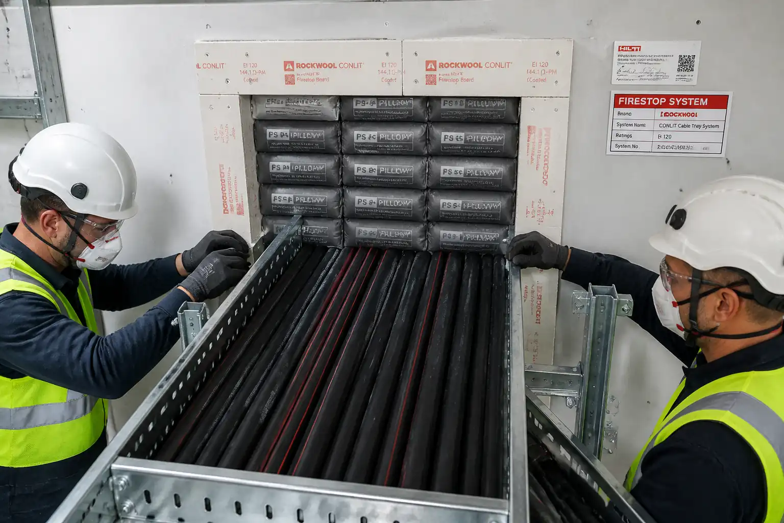
Inspection and Test Plan for Method Statement: Firestopping Using Multi‑Service Transit (MCT) Frames for Grouped Cables and Pipes
AI-assisted inspection and test plan connected to a method statement, with PDF and Excel export.
More than a static template
Unlike a downloadable Word or PDF template, this ITP is an AI-assisted editable starting point directly connected to its method statement. Every inspection activity, hold point, and acceptance criterion is structured and ready to adapt to your project.
- AI-assisted customization — Tailor inspection activities and acceptance criteria to your specific project scope.
- Linked method statement — This ITP is connected to the corresponding method statement describing the work sequence.
- Multiple export formats — Download as a formatted PDF or editable Excel spreadsheet.
- Editable starting point, not a final document — Review and verify all content against your project specifications and standards before use.
What you can customize
When you save this ITP to your account, every inspection row becomes editable. You can add, remove, or modify:
- Inspection activity — Description of what is being inspected.
- Inspection type — Hold point (H), Witness point (W), Review (R), or Monitor (M).
- Responsibility — Contractor, subcontractor, engineer, or client.
- Frequency — How often the inspection occurs.
- Acceptance criteria — Referenced standard or specification requirement.
- Records — Forms, test reports, or checklists required as evidence.
Why this ITP is used
To verify each transit meets the certified fire rating and any specified gastight/watertight requirements with full traceability.
Who uses this inspection and test plan
Contractor QA/QC, site engineers, installers, and the Client/Engineer representative.
When this ITP is prepared and submitted
From material receipt through final labeling and handover for each penetration.
Who receives or approves this ITP
Client/Engineer Representative
Inspection scope
Material approvals, substrate/opening verification, frame fixing, module selection/packing, compression torque, visual integrity, and tightness testing.
Typical hold, witness, and review points
HP1 – Module selection/pre-assembly; HP2 – Pre-test visual integrity; HP3 – Tightness test. Witness points for frame fixing and compression torquing.
Typical inspection records
MIRs, torque logs, pressure test reports with gauge calibration, bonding test sheets, photos, labels, and as-built register.
Important approval note
This ITP is an AI-assisted editable starting point, not a pre-approved document. Before use on any project, all inspection activities, hold points, and acceptance criteria must be reviewed and approved by the relevant parties (superintendent, principal contractor, or client representative) in accordance with your contract and project quality plan.
Always verify acceptance criteria against your applicable drawings, specifications, and regulatory requirements. Hold points must be confirmed with the relevant authority before work proceeds past that point.
Inspection and test plan
| Activity | Inspection / Test | Acceptance Criteria | Responsibility | Record |
|---|---|---|---|---|
| Material receipt and verification | Check approvals, batch numbers, damage | Materials per approved submittal; certificates available | QA/QC; Storekeeper | MIR; COC/ETA/UL listings; photos |
| Opening verification and frame layout | Dimensions, plumb/level, edge distances | Within specified tolerances; substrate sound | Site Engineer | Inspection checklist; layout sketch |
| Frame fixing (anchors/welds) | Anchor torque or weld VT | Per design/manufacturer; frame square/level | Installer; QA/QC | Torque/weld record; photos |
| Earthing/bonding (if required) | Continuity measurement | < 0.1 Ω to earth [Verify] | Electrician; QA/QC | Bonding test sheet |
| Service identification and OD measurement | Check IDs and OD vs module selection | Modules match OD range; no sheath damage | Discipline Supervisor; QA/QC | Service list; photos |
| Module selection and pre-assembly | Fit-up of split modules and reducers | Tight fit; correct stayplate plan | Installer; QA/QC; Engineer | HP1 form; photos |
| Module/stayplate installation | Visual continuity each row/layer | Flush seating; correct sequencing | Installer; QA/QC | Checklist; photos |
| Compression/wedge torquing | Torque measurement; indicator check | Within manufacturer torque/indicator limits | Installer; Torque Tech; QA/QC | Torque log; photo |
| Pre-test visual integrity | Visual both sides | No gaps; labeling space reserved | QA/QC; Engineer | HP2 sign-off |
| Tightness test (if specified) | Air/water pressure test to specified pressure/time | No leakage or unacceptable pressure drop [Verify] | Site Engineer; QA/QC; Engineer | Test report; gauge cal cert |
| Final labeling and as-built documentation | Check label accuracy and register | Transit ID, rating, date, installer present; register updated | Installer; QA/QC | Photos; register; handover dossier |
This table is a read-only public reference. Download the PDF or Excel version, or customize this ITP to edit it for your project.
Frequently asked questions
Related method statement
This Inspection and Test Plan is associated with the Method Statement: Firestopping Using Multi‑Service Transit (MCT) Frames for Grouped Cables and Pipes method statement, which describes the step-by-step construction sequence, resources, materials, equipment, safety controls, and environmental controls for this activity.
View the Method Statement: Firestopping Using Multi‑Service Transit (MCT) Frames for Grouped Cables and Pipes method statement →Continue with related inspection, method statement, article, and checklist resources.