Method Statement: Firestopping Using Multi‑Service Transit (MCT) Frames for Grouped Cables and Pipes – Method Statement
AI-assisted method statement with matching ITP, PDF download, and Excel export.
More than a static template
Unlike a downloadable Word or PDF template, this method statement is an AI-assisted editable starting point connected directly to a matching Inspection and Test Plan. Every section is structured, project-adaptable, and ready to export.
- AI-assisted drafting — Customize every section with AI for your specific project scope.
- Linked ITP — A matching inspection and test plan is generated alongside the method statement.
- Multiple export formats — Download as a formatted PDF or editable Excel spreadsheet.
- Editable starting point, not a final document — Review, verify, and adjust all content against your project requirements before use.
Static template vs. Quollnet workflow
| Feature | Static template | Quollnet |
|---|---|---|
| Project-specific content | Manual fill-in required | AI-assisted customization |
| Linked ITP | Separate document, no link | Matching ITP included |
| Export formats | Usually PDF only | PDF and Excel |
| Structured sections | Free-form layout | 13 standardized sections |
| Saved to your account | Local file only | Cloud-saved, reusable |
| Content accuracy | You verify everything | AI-assisted, you still verify |
| Cost | Often free but time-intensive | Free to customize and download |
What you can customize
When you save this method statement to your account, every section becomes editable. The following 13 sections are included:
- Scope — Defines the activity and its boundaries.
- References — Standards, specifications, and drawings.
- Responsibilities — Roles and accountabilities.
- Resources — Labour, plant, and equipment summary.
- Materials — Materials and compliance requirements.
- Equipment — Tools and equipment details.
- Prerequisites — Hold points and pre-conditions.
- Method sequence — Step-by-step construction sequence.
- Safety controls — HSE risk controls and PPE.
- Environmental controls — Environmental mitigation measures.
- QA/QC — Quality inspection and test requirements.
- ITP — Inspection and Test Plan table (has its own page).
- Attachments — Referenced drawings and documentation.
Why this method statement is used
This method statement is used to define and communicate the approved procedure for carrying out method statement: firestopping using multi‑service transit (mct) frames for grouped cables and pipes on site. It ensures the work is planned in advance, the correct resources and controls are in place, and all personnel understand responsibilities, sequence, quality requirements, and safety controls before work begins. It aligns site execution with the documented scope and acceptance expectations.
Who uses this method statement
This method statement is used by contractors, site supervisors, project engineers, QA/QC engineers, HSE officers, consultants, and client representatives. It serves as a shared reference for planning, execution, supervision, inspection, and approval of the activity on site.
When it is prepared and submitted
The method statement is prepared before the work activity starts and submitted as part of the pre-construction documentation package for review and approval.
Who reviews or approves it
The method statement is usually submitted to the client representative, consultant, resident engineer, or project management consultant for review and approval before the work commences.
Important approval note
This method statement is an AI-assisted editable starting point, not a pre-approved document. Before use on any project, all content must be reviewed and approved by the relevant parties (superintendent, principal contractor, or client representative) in accordance with your contract and project quality plan.
For example: if your specification requires a departure from a referenced standard, that departure must be documented and approved separately — this method statement will not capture that automatically. Always verify against your applicable drawings, specifications, and regulatory requirements.
Method statement content
Scope
Overview
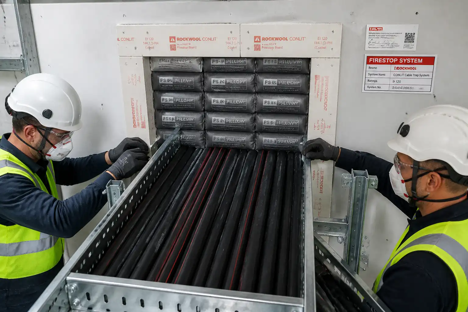
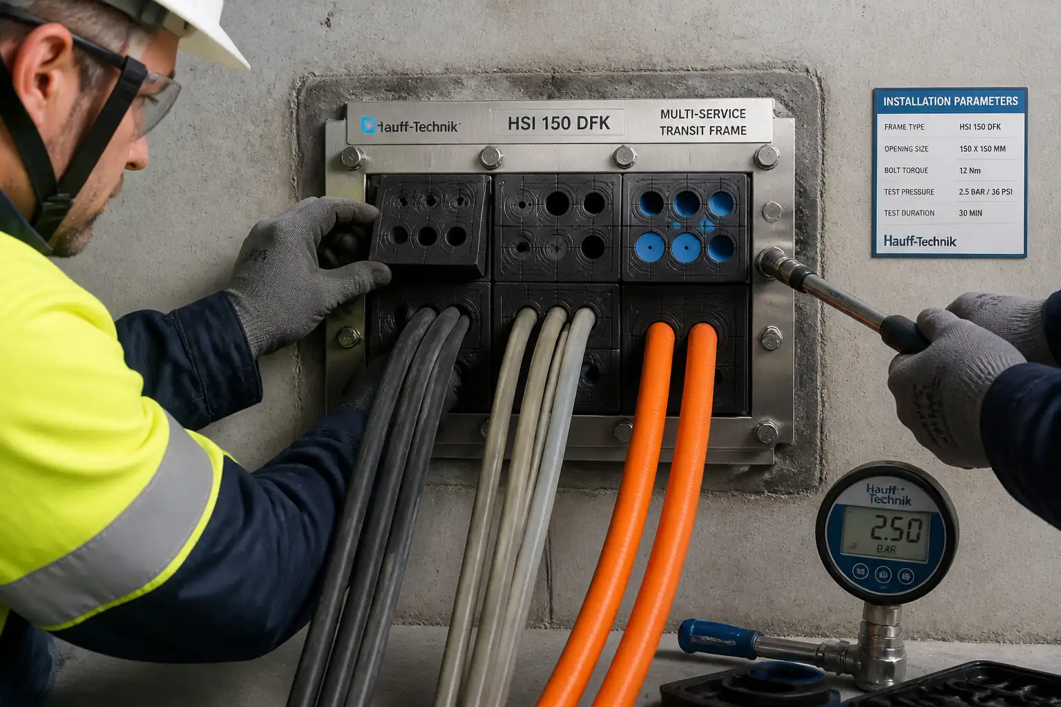
This method statement covers procurement, inspection, installation, compression, and verification of multi‑service transit (MCT) frames and sealing modules for grouped electrical cables and small-bore pipes passing through walls/floors forming fire, smoke, and/or pressure barriers. It includes frame fixing, module selection to cable/pipe ODs, insertion of stayplates and wedges/compression units, application of approved lubricant, provision of blank modules for future capacity, pressure testing where specified, labeling, and documentation.
Inclusions
- Carbon/galvanized/SS frame supply and fixing to concrete/masonry/steel bulkheads.
- Identification and measurement of all passing services; cable/pipe routing, bend-radius protection, and grouping within frame apertures.
- Installation of split sealing modules (and reducer layers where system requires), stayplates, and compression/wedge blocks with controlled torque/compression.
- Fire rating compliance (e.g., EI 60/90/120) or UL F/T ratings per tested assembly for the specific substrate and service mix.
- Pressure or leak testing for gastight/watertight transits where required.
- Earthing/bonding of metallic frames where applicable.
- Quality records, labels/certificates, and as-built schedules.
Exclusions
- Structural opening creation beyond minor trimming and drilling for anchors unless noted.
- Relocation of services, temporary works for major coring, or cable terminations.
- Fire detection/alarms, passive protection beyond the MCT system.
Key Performance Targets
- Fire rating: As per tested/approved system for each opening [Verify per project specifications].
- Tightness: Air/water test pressure and duration per project/manufacturer (typ. 0.5–1.5 bar for 10–30 min) [Verify].
- Visual finish: No visible gaps; modules flush; frame plumb/level within ±2 mm; compression indicators satisfied.
References
| Document Type | Reference / Number | Revision | Notes |
|---|---|---|---|
| Standard | ASTM E814; UL 1479 | Applicability depends on certification of selected MCT system. | |
| Standard | ASTM E1966; UL 2079 | Use only if joints/movement are in scope. | |
| Standard | BS EN 1366‑3 | Common in EU/UK projects. | |
| Standard | BS EN 13501‑2 | Classification EI for walls/floors. | |
| Standard | ISO 9001; ISO 14001; ISO 45001 | For contractor and manufacturer management systems. | |
| Code | NFPA 70; IEC 60364 | For cable handling and routing through transits. | |
| Approval | e.g., ETA, UL System No., DoP | Must match substrate, service types, and rating required. [Verify per project specifications]. |
Responsibilities
| Role | Responsibility | Name / Party |
|---|---|---|
| PM | Approve method, ensure interfaces. | Contractor |
| Engineer | Daily supervision and ITP compliance. | Contractor |
| QA/QC | Hold/Witness point coordination. | Contractor |
| HSE | Verify controls and PPE compliance. | Contractor |
| Supervisor | Coordinate with operations/users. | Contractor |
| Engineer | Authorize proceed at HPs. | Client/Engineer |
Resources
| Resource Type | Description | Quantity | Remarks |
|---|---|---|---|
| Labor | Technicians trained/authorized by system manufacturer. | 2–4 per crew [Verify] | |
| Labor | Controls torque application and calibration logs. | 1 per crew | |
| Staff | Performs checks and coordinates HP/WP. | As required |
Materials
| Material | Specification / Grade | Quantity | Remarks |
|---|---|---|---|
| Frame | As per drawings | ||
| Modules | As scheduled +10% spares [Verify] | ||
| Stayplates | Per aperture | ||
| Wedge | Per aperture | ||
| Lubricant | As required | ||
| Anchors | As required | ||
| Bonding kit | As required | ||
| Labels | Per transit |
Equipment
| Equipment | Capacity / Type | Quantity | Inspection Required |
|---|---|---|---|
| Measuring | Set per crew | ||
| Torque wrench | 1–2 per crew | ||
| Hand tools | Set per crew | ||
| Drilling | As required | ||
| Pressure kit | Up to 3 bar | 1 set | |
| PPE | Per person |
Prerequisites
Approvals and Documentation
- Approved shop drawings and transit schedule identifying each opening, required fire rating (e.g., EI 120), and any pressure/gastight class. Unique transit IDs assigned.
- Approved material submittals including system approvals (UL/ETA), data sheets, and SDS.
- Risk Assessment/Method Statement (RAMS) briefed to crew; permits prepared (Hot Work, Work at Height, Confined Space) as applicable. [Verify per project HSE plan and local regulations]
Site Conditions
- Openings formed to correct size and location; substrates sound, clean, and dry. Edges free of laitance, oil, loose material; steel edges de-burred and anti-corrosion treated.
- Edge distances for anchors and minimum member thickness verified per anchor ETA/ACI 318 [Verify].
- Services identified and isolated or protected. LOTO applied when feasible; if live cables must remain energized, establish no‑contact and insulated tool procedures with permit.
- Cable minimum bend radius and pulling tensions confirmed (per cable manufacturer/NFPA 70/IEC 60364). Supports/rollers in place to avoid sheath damage.
Tools and Calibration
- Torque wrenches and pressure gauges within calibration; certificates available.
- Pressure test adapters/fittings compatible with the selected MCT system.
Coordination
- Sequence coordinated with MEP installation to minimize rework and ensure spare capacity modules installed per schedule.
- Fire stopping of mixed services matches the tested configuration (e.g., power + control cables, metallic/nonmetallic pipes) or obtain engineering assessment from manufacturer/third party prior to work.
Method Sequence
| Step | Activity | Description | Responsibility | Inspection / Hold Point |
|---|---|---|---|---|
| 1 | Receipt and storage | Receive frames, modules, wedges, stayplates, lubricant. Verify quantities, damage, batch numbers; store upright, dry, 5–35°C. | Storekeeper / QA/QC | Incoming inspection (MIR) |
| 2 | Opening verification and layout | Confirm opening size vs. frame external dimensions and tolerance. Check plumb/level; mark fixing holes per template. | Site Engineer | Check |
| 3 | Surface preparation | Clean substrate; drill anchors or prepare weld areas; de-burr steel; apply primer/anti-corrosion as specified. | Installer | Surveillance |
| 4 | Frame positioning and fixing | Place frame flush to face; ensure correct orientation (label side). Fix using anchors or welds as per drawings. For cast-in frames, verify formwork alignment. | Installer / Welder | Witness |
| 5 | Earthing/bonding (if required) | Install bonding strap from frame to building earth; test continuity. | Electrician | Witness |
| 6 | Service preparation and identification | Verify each cable/pipe ID, OD, material, and required module size. Protect sheaths; ensure bend radius respected. | Discipline Supervisor | Check |
| 7 | Module selection and pre-assembly | Select split modules to suit measured ODs; remove/add reducer layers as needed. Pre-lube module contact surfaces lightly. | Installer | Hold Point HP1 |
| 8 | Insertion of modules and stayplates | Insert modules from one side with stayplates between module layers per system manual. Maintain service centering; avoid twisting cables. | Installer | Surveillance |
| 9 | Spare capacity provision | Install blank modules and stayplates to fill designated spare openings. Mark spares on label/as-built. | Installer | Check |
| 10 | Compression/wedge installation | Install wedge/compression unit(s). Tighten bolts evenly to specified torque or until compression indicators show final set per manufacturer. | Installer / Torque Technician | Witness |
| 11 | Visual integrity check | Inspect both sides: flushness, continuity, gaps, labeling space reserved. | QA/QC | Hold Point HP2 |
| 12 | Tightness test (where specified) | Fit test adapter; apply air or water to specified pressure (e.g., 1.0 bar) for specified duration (e.g., 10–30 min). Monitor gauge; apply leak-detect solution for air tests. | Site Engineer / QA/QC | Hold Point HP3 |
| 13 | Firestop labeling and documentation | Affix durable label stating system ID, fire rating, installer, date. Update register with services, ODs, spare modules. | Installer / QA/QC | Check |
| 14 | Handover | Submit as-builts, approvals, ITPs, test results. Close NCRs/punch items. | Project Engineer | Final inspection |
Safety Controls
Task-Specific Hazards and Controls
- Hazard: Drilling/anchoring into concrete or steel (silica/metal dust, flying debris)
- Likely consequence: Eye injury, respiratory irritation, hearing loss.
- Engineering/procedural control: Use dust extraction, wet drilling where compatible with system; shrouded bits; establish exclusion zone; secure workpiece; follow anchor ETA for edge distances to prevent breakout.
- Required PPE: Safety glasses or face shield, hearing protection, cut-resistant gloves, FFP2/3 respirator where dusty.
- Collective preventive measure: Local exhaust ventilation (LEV), barriers and signage.
-
Inspection/permit/supervision: Pre-use tool inspection; PAT testing; HSE supervision; confirm permits for noisy works where required.
-
Hazard: Contact with live cables during routing
- Likely consequence: Electric shock, arc flash, equipment damage.
- Engineering/procedural control: LOTO and prove-dead where feasible; insulated tools; maintain clearance; implement Live Working Permit if isolation not possible, with voltage-rated gloves/mats and approach boundaries. [Verify per project HSE plan and local regulations]
- Required PPE: Arc-rated clothing as required, insulated gloves, safety glasses.
- Collective preventive measure: Barriers and watchman; lockable covers on energized equipment.
-
Inspection/permit/supervision: Electrical PTW/LOTO documentation; supervision by authorized electrician.
-
Hazard: Pinch points during wedge compression/torquing
- Likely consequence: Hand/finger injuries.
- Engineering/procedural control: Use correct tools and controlled torque; keep hands clear of moving parts; use rubber mallet only where specified.
- Required PPE: Cut-resistant gloves.
- Collective preventive measure: Work positioning to avoid hand entrapment; buddy system during compression.
-
Inspection/permit/supervision: Supervisor brief and observation.
-
Hazard: Hot work (welding frames to steel bulkheads)
- Likely consequence: Burns, fire, fumes.
- Engineering/procedural control: Hot Work Permit; fire blankets; maintain fire watch; local extraction/ventilation; gas monitoring if in confined/poorly ventilated spaces.
- Required PPE: Welding hood, leather gloves, FR clothing, safety boots.
- Collective preventive measure: Fire extinguishers within 5 m; spark containment.
-
Inspection/permit/supervision: Hot Work Permit; fire watch 30 min post‑work; inspect for smoldering.
-
Hazard: Manual handling of frames and bundles of modules
- Likely consequence: Musculoskeletal strain, crush injuries.
- Engineering/procedural control: Team lift; use carts/lifters; limit lift weights per policy.
- Required PPE: Safety footwear, gloves.
- Collective preventive measure: Material staging plan to minimize carries.
-
Inspection/permit/supervision: Toolbox talk; supervisor monitoring.
-
Hazard: Pressure testing (stored energy)
- Likely consequence: Hose whip, gauge failure, sudden release causing impact.
- Engineering/procedural control: Use rated hoses with whip checks; pressurize gradually; stand clear; shield gauges; do not exceed test pressure.
- Required PPE: Eye protection, gloves.
- Collective preventive measure: Barriers during test; relief valve on test rig.
-
Inspection/permit/supervision: Calibrated gauges; approved test procedure; engineer witness (HP3).
-
Hazard: Chemical exposure to lubricant/sealants
- Likely consequence: Skin/eye irritation, slips.
- Engineering/procedural control: Use approved, low-toxicity lubricant; apply sparingly; clean spills immediately.
- Required PPE: Nitrile gloves, safety glasses.
- Collective preventive measure: Spill kit at workface.
-
Inspection/permit/supervision: SDS available; COSHH assessment [Verify].
-
Hazard: Working at height to access elevated penetrations
- Likely consequence: Falls.
- Engineering/procedural control: Use certified podiums/scaffolds; inspect before use; maintain three points of contact on ladders for short-duration work only.
- Required PPE: Fall arrest where required, safety harness on approved anchor.
- Collective preventive measure: Edge protection/guardrails.
- Inspection/permit/supervision: Work at Height Permit; daily scaffold/MEWP inspection.
Environmental Controls
Controls
- Dust and noise from drilling
- Impact: Air quality degradation; nuisance.
- Control: Use dust extraction and dampening; schedule noisy tasks during permitted hours; hearing protection provided; comply with site noise limits [Verify].
-
Monitoring: Spot checks with dust/noise meters where required.
-
Waste elastomer modules, packaging, and offcuts
- Impact: Solid waste.
- Control: Segregate by polymer type where feasible; return unused modules to sealed storage; recycle cardboard/plastics; dispose per local regulations.
-
Records: Waste transfer notes.
-
Lubricant/spill management
- Impact: Slip risk; water contamination.
- Control: Use water-based lubricants; spill kits on hand; prevent discharge to drains.
-
Records: Spill log if applicable.
-
VOCs/fumes from hot work coatings
- Impact: Air emissions.
- Control: Low-VOC primers where possible; local ventilation; cover and protect adjacent sensitive equipment.
-
Records: SDS; ventilation logs if required.
-
Energy and resource use
- Impact: Carbon footprint.
- Control: Use battery tools with dust extraction; shut down idle equipment; consolidate deliveries.
Quality Assurance / Quality Control
General
- All works executed by manufacturer-certified installers; follow tested system manual for the exact substrate and service mix.
- No substitution of modules or lubricant without written approval.
Inspection and Testing
- 100% visual inspection of each installed transit against drawings and system manual.
- Torque verification: 100% of wedges/compression bolts recorded on torque log; tolerances per manufacturer (typ. ±10% of target) [Verify].
- Pressure/leak testing: Where required for gastight/watertight barriers, test each transit or as per specification (typ. 100% critical areas; 10% sample elsewhere) at specified pressure/duration [Verify].
- Earthing continuity (if applicable): Measure resistance using calibrated meter; acceptance < 0.1 Ω [Verify].
Acceptance Criteria (example benchmarks; verify per project/manufacturer)
- Fire rating: Matches approved listing (e.g., EI 120) for the exact configuration.
- Frame position: Level/plumb within ±2 mm; diagonals within 3 mm; anchors torqued to spec; welds continuous/sound (VT level per AWS D1.1 if welded) [Verify].
- Modules: Correct size for measured OD; flush with frame face; no visible pathways; stayplates correctly interleaved.
- Compression: Wedge seated; compression indicator engaged or bolt torque within specified range; no over‑compression or extrusion beyond manufacturer tolerance.
- Labeling: Durable label installed with system ID, rating, date, installer, transit ID; as‑built updated.
Records and Traceability
- Material certificates/approvals; batch numbers of modules and lubricant.
- ITP forms with HP/WP sign-offs; torque logs; pressure test reports (gauge ID and calibration).
- Photo records (both sides) before and after compression; label close-up.
Nonconformance and Rework
- Any leakage, mis-sized modules, or damage to services triggers NCR. Defect rectified by re‑packing with correct modules, re‑compression, and re‑test. Document close-out.
Calibration
- Torque wrenches: Calibrated at ≤6‑month intervals or after impact; records retained.
- Pressure gauges: Calibrated annually or per spec; accuracy class documented.
Attachments
- Manufacturer’s installation manual and system approvals (UL system numbers / ETA, DoP)
- SDS for lubricant, primers, coatings
- Transit schedule and shop drawings with unique IDs
- Sample torque log sheet and pressure test report template
- Calibration certificates for torque wrenches and pressure gauges
- Example firestop label layout and coding convention
- Risk Assessment and Permits (Hot Work, Work at Height, Electrical LOTO)
This content is a read-only public reference. Download or customize to get an editable version.
ITP preview
The first inspection activities from the linked ITP for Method Statement: Firestopping Using Multi‑Service Transit (MCT) Frames for Grouped Cables and Pipes:
| Activity | Inspection / Test | Acceptance Criteria | Responsibility | Record |
|---|---|---|---|---|
| Material receipt and verification | Check approvals, batch numbers, damage | Materials per approved submittal; certificates available | QA/QC; Storekeeper | MIR; COC/ETA/UL listings; photos |
| Opening verification and frame layout | Dimensions, plumb/level, edge distances | Within specified tolerances; substrate sound | Site Engineer | Inspection checklist; layout sketch |
| Frame fixing (anchors/welds) | Anchor torque or weld VT | Per design/manufacturer; frame square/level | Installer; QA/QC | Torque/weld record; photos |
Showing 3 of 11 inspection activities. View full ITP →
Related Inspection and Test Plan
An Inspection and Test Plan (ITP) is available for Method Statement: Firestopping Using Multi‑Service Transit (MCT) Frames for Grouped Cables and Pipes. The ITP defines the inspection activities, acceptance criteria, hold and witness points, responsible parties, and records required to verify the work described in this method statement.
View the Method Statement: Firestopping Using Multi‑Service Transit (MCT) Frames for Grouped Cables and Pipes ITP →Frequently asked questions
Continue with related Quollnet resources connected to this method statement.