Method Statement: Firestopping of Cable Bundles and Cable Trays Penetrating Fire-Rated Barriers (Intumescent Mastic/Sealant) – Method Statement
AI-assisted method statement with matching ITP, PDF download, and Excel export.
More than a static template
Unlike a downloadable Word or PDF template, this method statement is an AI-assisted editable starting point connected directly to a matching Inspection and Test Plan. Every section is structured, project-adaptable, and ready to export.
- AI-assisted drafting — Customize every section with AI for your specific project scope.
- Linked ITP — A matching inspection and test plan is generated alongside the method statement.
- Multiple export formats — Download as a formatted PDF or editable Excel spreadsheet.
- Editable starting point, not a final document — Review, verify, and adjust all content against your project requirements before use.
Static template vs. Quollnet workflow
| Feature | Static template | Quollnet |
|---|---|---|
| Project-specific content | Manual fill-in required | AI-assisted customization |
| Linked ITP | Separate document, no link | Matching ITP included |
| Export formats | Usually PDF only | PDF and Excel |
| Structured sections | Free-form layout | 13 standardized sections |
| Saved to your account | Local file only | Cloud-saved, reusable |
| Content accuracy | You verify everything | AI-assisted, you still verify |
| Cost | Often free but time-intensive | Free to customize and download |
What you can customize
When you save this method statement to your account, every section becomes editable. The following 13 sections are included:
- Scope — Defines the activity and its boundaries.
- References — Standards, specifications, and drawings.
- Responsibilities — Roles and accountabilities.
- Resources — Labour, plant, and equipment summary.
- Materials — Materials and compliance requirements.
- Equipment — Tools and equipment details.
- Prerequisites — Hold points and pre-conditions.
- Method sequence — Step-by-step construction sequence.
- Safety controls — HSE risk controls and PPE.
- Environmental controls — Environmental mitigation measures.
- QA/QC — Quality inspection and test requirements.
- ITP — Inspection and Test Plan table (has its own page).
- Attachments — Referenced drawings and documentation.
Why this method statement is used
This method statement is used to define and communicate the approved procedure for carrying out method statement: firestopping of cable bundles and cable trays penetrating fire-rated barriers (intumescent mastic/sealant) on site. It ensures the work is planned in advance, the correct resources and controls are in place, and all personnel understand responsibilities, sequence, quality requirements, and safety controls before work begins. It aligns site execution with the documented scope and acceptance expectations.
Who uses this method statement
This method statement is used by contractors, site supervisors, project engineers, QA/QC engineers, HSE officers, consultants, and client representatives. It serves as a shared reference for planning, execution, supervision, inspection, and approval of the activity on site.
When it is prepared and submitted
The method statement is prepared before the work activity starts and submitted as part of the pre-construction documentation package for review and approval.
Who reviews or approves it
The method statement is usually submitted to the client representative, consultant, resident engineer, or project management consultant for review and approval before the work commences.
Important approval note
This method statement is an AI-assisted editable starting point, not a pre-approved document. Before use on any project, all content must be reviewed and approved by the relevant parties (superintendent, principal contractor, or client representative) in accordance with your contract and project quality plan.
For example: if your specification requires a departure from a referenced standard, that departure must be documented and approved separately — this method statement will not capture that automatically. Always verify against your applicable drawings, specifications, and regulatory requirements.
Method statement content
Scope
Scope of Works
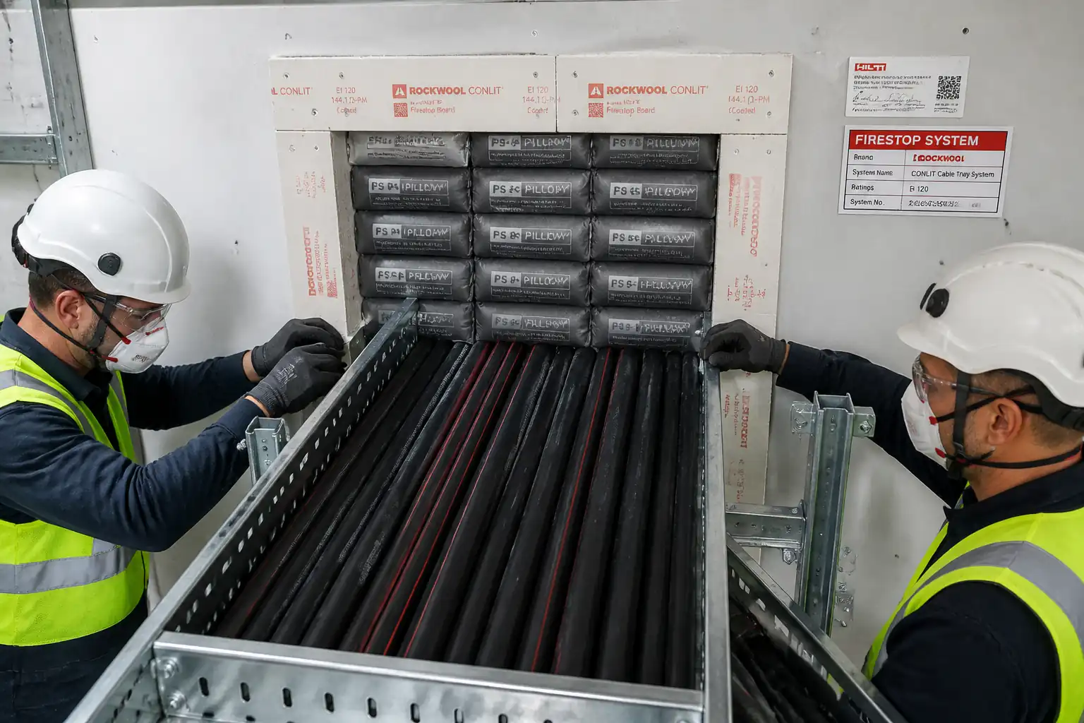
- Provide complete firestopping of electrical and ICT cable bundles and cable trays (ladder/trough/basket) penetrating fire-rated walls and floors using tested and approved intumescent mastic/sealant systems with mineral wool backing or as per the approved system listing.
- Activities include: verification of approved system listings, surface preparation, cable separation/management at the penetration, installation of sleeves/backing where required, application of intumescent mastic/sealant to specified depth and coverage, reinstatement of barrier integrity, installation of identification tags, and QA/QC inspection including measurement of seal depth and continuity.
- Exclusions: Structural modifications to barriers beyond minor trimming, re-routing of services, and permanent fire-rated enclosures external to the penetration unless noted.
- Locations: All project areas where cables/trays pass through fire-rated walls/floors per approved drawings.
- Fire ratings targeted: 1–4 hours F and T ratings [Verify per project specifications and approved system listing].
- Deliverables: Installed and labeled firestop systems with as-built records, inspection reports, and manufacturer approvals/COC.
References
| Document Type | Reference / Number | Revision | Notes |
|---|---|---|---|
| ASTM E814 / UL 1479 | Fire tests of through-penetration firestops (cables/cable trays). Acceptance basis for F/T rating. | ||
| ASTM E2174 | On-site inspection of fire stops for penetrating items; sampling and destructive testing options. | ||
| EN 1366-3 / EN 13501-2 | European fire resistance tests for service installations – penetration seals and classification. | ||
| NFPA 70 (NEC) / NEMA VE 2 | Cable and cable tray installation clearances, supports, and fill guidance adjacent to penetrations. | ||
| Manufacturer’s TDS/SDS and UL/ETA System Listings | Product-specific installation parameters, approved configurations, environmental limits, and safety. | ||
| Project Specifications and Drawings | Project fire rating requirements, identification/labelling standards, and records. [Verify] | ||
| Local Building/Fire Codes | Permitting, inspection, and acceptance by AHJ. [Verify per local regulations] |
Responsibilities
| Role | Responsibility | Name / Party |
|---|---|---|
| Project Manager | Project Manager | |
| Site Engineer | Site Engineer | |
| Supervisor | Firestop Supervisor (Competent Person) | |
| Foreman | Electrician/ELV Foreman | |
| QA/QC Engineer | QA/QC Engineer | |
| HSE Officer | HSE Officer | |
| Independent Inspector | Third-Party Firestop Inspector (if applicable) | |
| OEM Rep | Manufacturer’s Technical Representative (as needed) |
Resources
| Resource Type | Description | Quantity | Remarks |
|---|---|---|---|
| Manpower | 2–6 | Training per manufacturer required. | |
| Manpower | 2–4 | ||
| Manpower | 1 | ||
| Manpower | 1 |
Materials
| Material | Specification / Grade | Quantity | Remarks |
|---|---|---|---|
| Intumescent firestop mastic/sealant | ASTM E814/UL 1479 or EN 1366-3 tested; F/T rating per system [Verify]. | As required | Install per specific UL/ETA listing for cable bundles/trays. |
| Mineral wool (stone wool) | Noncombustible; melt point >1000°C; per UL/ETA system. | As required | Compression 25–50% to fit annulus. |
| Steel sleeve (galv. or stainless) | Wall thickness and size per UL/ETA system [Verify]. | As required | Sleeve material and protrusion per listing. |
| Primer (if required) | Per manufacturer’s TDS; compatibility verified. | As required | Manufacturer-approved only. |
| Cleaner/degreaser | OEM-recommended; non-chlorinated. | As required | Follow SDS and ventilation controls. |
| Identification tag and fasteners | SS/Al or high-temp plastic; label content per project. | 1 per penetration | UV and solvent resistant. |
Equipment
| Equipment | Capacity / Type | Quantity | Inspection Required |
|---|---|---|---|
| Caulking/dispensing guns | Sufficient for crews | ||
| Hand tools for sealing/finishing | Sets per crew | ||
| Rotary hammer/grinder with masonry bits | As needed | ||
| Industrial vacuum (HEPA) | 1 per area | ||
| Measuring gauge/calipers and depth probe | Per inspector | ||
| Access equipment (ladder, podium, scaffold) | As required |
Prerequisites
Pre-Start Requirements
- Approvals: Method Statement, ITP, material submittals (TDS/SDS), and specific UL/ETA/approved system listings for each penetration configuration approved by Consultant/AHJ.
- Training: Firestop installers certified/briefed by manufacturer. Toolbox talk delivered addressing task HSE controls.
- Mock-up: Construct and approve at least one representative penetration mock-up prior to production works [Verify requirement per project].
- Coordination: Confirm cable routing is final; ensure adequate slack for manipulation; confirm required supports within 300–600 mm of each side of barrier [Verify per NEC/NEMA and structural approval].
- Permits: Hot work not expected; obtain Electrical Isolation/LOTO or “Work Near Live Services” permit if live adjacent systems exist. Confined space permit if inside risers/shafts [Verify per project HSE plan].
- Environmental: Substrate temperature and ambient within manufacturer range (typically 5–40°C) and moisture/dust-free. Maintain ventilation for VOC control in enclosed spaces.
- Tools & Calibrations: Depth probes, gauges, and measuring devices available and verified. Dispensing guns compatible with product viscosity.
- Materials: Check shelf life and batch numbers; store per TDS (cool, dry, upright). Primer availability if required by substrate condition.
- Area Handover: Barriers complete and rated; openings accessible; adjacent surfaces protected with masking where needed.
- Inspection Notifications: Notify QA/QC and (if applicable) third-party inspector of hold/witness points as per ITP.
Method Sequence
| Step | Activity | Description | Responsibility | Inspection / Hold Point |
|---|---|---|---|---|
| 1 | Confirm approved firestop system | Identify each penetration type (wall/floor, thickness, cable types/sizes, tray type/width, spacing). Select corresponding UL/ETA listing and ensure it matches field conditions (annular space, sealant type, backing, sleeve presence). | Site Engineer / Firestop Supervisor | Hold Point HP-1: System verification before works |
| 2 | Prepare area and protect services | Erect access platform; install temporary supports to trays/cables so no load is transmitted to the barrier or firestop. Mask adjacent finishes if required. | Firestop Supervisor / Electrician | Visual |
| 3 | Surface and opening preparation | Clean opening and cable/tray surfaces of dust, laitance, oil, and loose particles using HEPA vacuum and lint-free wipes. Ensure substrate is sound and dry. If trimming is required, cut to achieve annular space per listing and repair spalls. | Firestop Installers | Witness Point WP-1 |
| 4 | Cable arrangement and separation | Gently separate or organize cables within the opening to allow sealant wetting between cables and between cables and sleeve/opening. Remove combustible temporary wraps/foams not part of the system. Do not exceed tray fill limits. | Electrician / ELV Technicians | Visual |
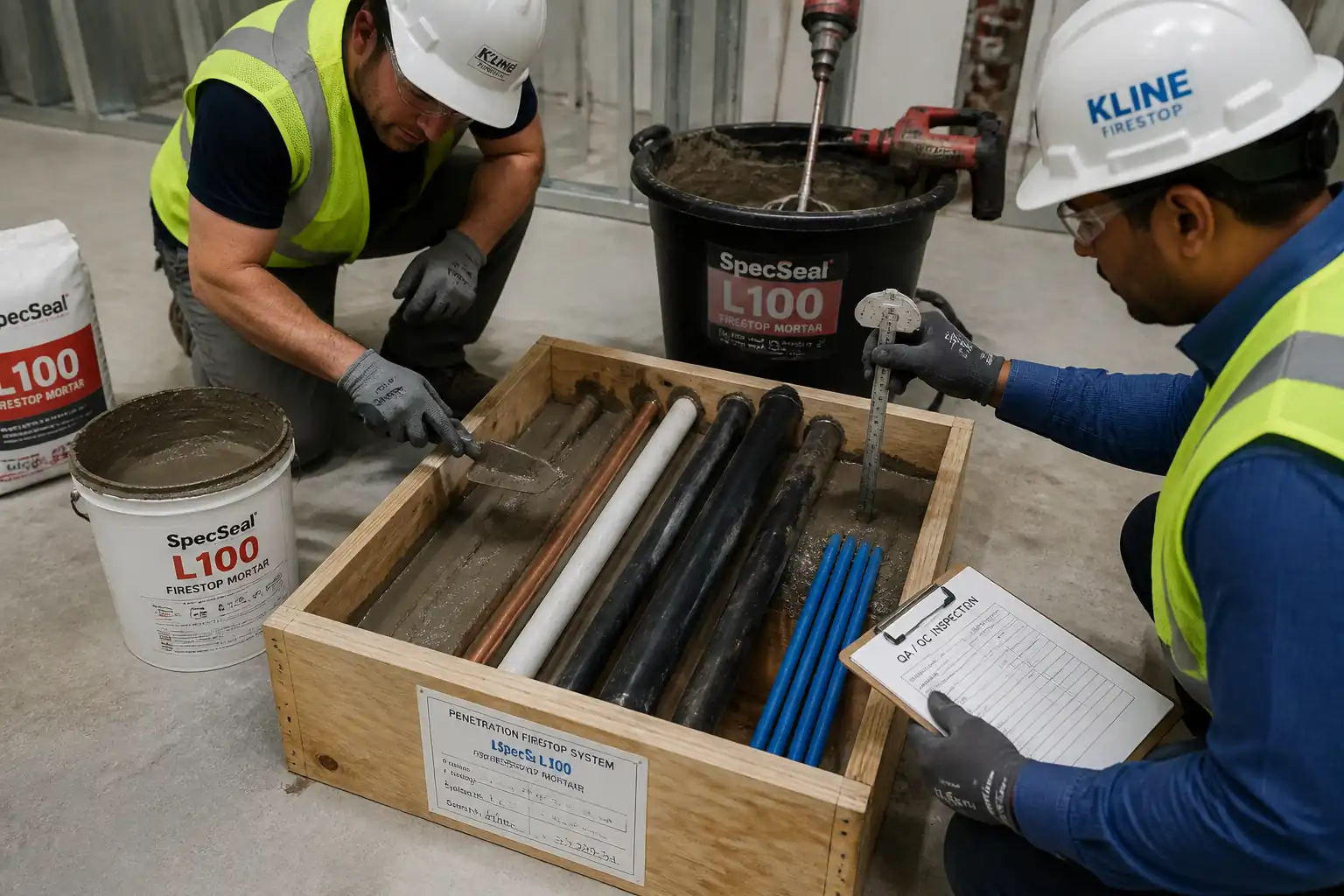
| 5 | Install backing material | Pack mineral wool into annular space to required depth and compression (typically 25–50% compression) leaving a recess for sealant depth per listing. For floors, provide formwork/board support if required to prevent slump. | Firestop Installers | Witness Point WP-2 |
| 6 | Apply primer (if specified) | Prime substrate/cable jackets where required by the sealant manufacturer. Allow to flash-off per TDS. | Firestop Installers | Visual |
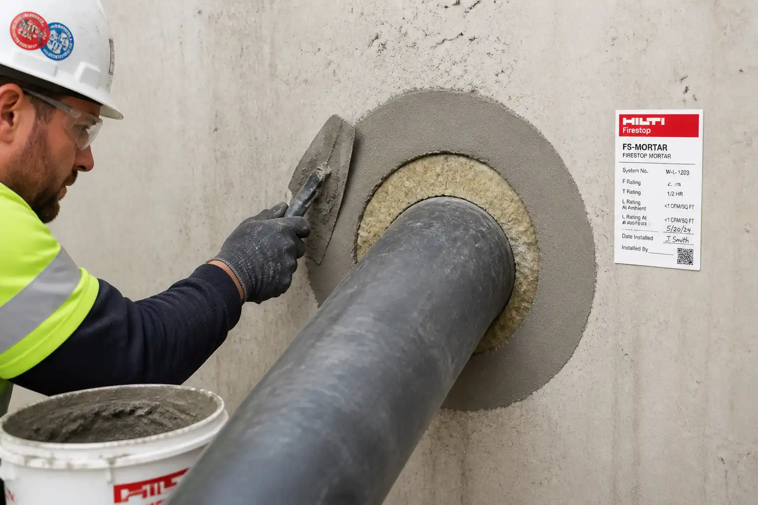
| 7 | Sealant application – injection and face sealing | Using appropriate nozzle, inject intumescent sealant to fill interstices between cables and to the full required depth from both sides (wall) or from top/bottom (floor) as per listing. Tool the face to a smooth finish with minimum 10 mm lap onto substrate/sleeve. Maintain continuous contact around every cable and tray edge. | Firestop Installers | Witness Point WP-3 |
| 8 | Finish, cure and protection | Remove masking; clean adjacent surfaces. Protect the seal from disturbance until skin/initial cure achieved (typically 24–48 h) [Verify per TDS]. Prevent loading/impact to the seal. | Firestop Supervisor | Visual |
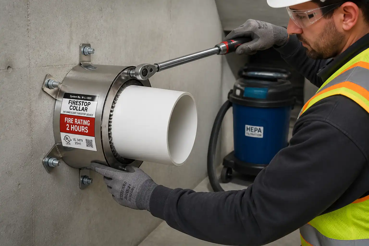
| 9 | Install identification tag/label | Fix durable identification tag adjacent to penetration on accessible side(s). Include: Firestop System ID (e.g., UL System No.), product name, F/T rating, installer, date, and unique penetration ID linked to as-built schedule. | Firestop Installers | Visual |
| 10 | QA/QC inspection and sign-off | Perform 100% visual inspection; verify sealant depth with probe at representative points; check adhesion and continuity; confirm supports installed and no load on firestop; update records and as-builts. Arrange third-party inspection if required by ITP/AHJ. | QA/QC Engineer | Hold Point HP-2: Final inspection |
| 11 | Closeout and handover | Submit as-built penetration schedule, system listings, product batch numbers, and inspection/third-party reports. Brief O&M on re-penetration control and maintenance. | Project Manager / QA/QC | Document review |
Safety Controls
Task-Specific HSE Controls
- Hazard: Working near live electrical systems
- Consequence: Electric shock, arc flash, burns
- Engineering/Procedural Control: Coordinate isolation/LOTO where feasible; use insulated tools; maintain safe approach distances; no cutting/abrasion of cable jackets; verify cable identification with electrician.
- Required PPE: Electrical-rated gloves where required, safety glasses/face shield, FR clothing if arc risk, dielectric footwear [Verify per project HSE plan and local regulations].
- Collective Measure: Barriers and signage establishing an exclusion zone; supervisor control of access.
-
Inspection/Permit/Supervision: Electrical work permit/LOTO documentation; HSE officer verification; competent electrician present.
-
Hazard: Dust and silica from trimming masonry openings
- Consequence: Respiratory irritation, silicosis, eye injury
- Engineering/Procedural Control: Use wet-cutting or on-tool HEPA extraction; minimize cutting; preformed sleeves where possible.
- Required PPE: FFP3/N99 respirator, safety goggles, gloves, long sleeves.
- Collective Measure: Local extraction/ventilation; dust barriers for occupied areas.
-
Inspection/Permit/Supervision: Tool inspection and PAT; dust control plan review.
-
Hazard: Falls from height when accessing high penetrations
- Consequence: Serious injury or fatality
- Engineering/Procedural Control: Use certified mobile scaffold/podium; three points of contact on ladders for inspection only; never overreach; maintain guardrails/toeboards.
- Required PPE: Full-body harness with lanyard if fall arrest required, safety helmet with chin strap, non-slip footwear.
- Collective Measure: Edge protection; properly tagged access equipment (daily pre-use checks).
-
Inspection/Permit/Supervision: Working at Height permit; competent person to inspect platforms.
-
Hazard: Chemical exposure to intumescent sealants/primers (VOCs, skin/eye irritants)
- Consequence: Dermatitis, respiratory irritation, eye injury
- Engineering/Procedural Control: Review SDS; ensure ventilation; avoid skin contact; decant carefully; prohibit ignition sources if flammable solvents present.
- Required PPE: Nitrile gloves, safety glasses/goggles, disposable coveralls in confined areas; half-mask respirator with organic vapor cartridges where ventilation inadequate [Verify].
- Collective Measure: Local exhaust; spill kit and sealed waste containers on site.
-
Inspection/Permit/Supervision: SDS available; HSE walkthrough; check product expiry and storage.
-
Hazard: Manual handling of mineral wool, sealant cases, and access equipment
- Consequence: Strains, cuts, irritation
- Engineering/Procedural Control: Team lifts; use carts; pre-stage materials; cut mineral wool with long knife on stable bench.
- Required PPE: Cut-resistant gloves, long sleeves, safety glasses.
- Collective Measure: Material handling plan; clear walkways.
-
Inspection/Permit/Supervision: Supervisor to brief lifting technique; housekeeping inspections.
-
Hazard: Tray/cable instability or overloading near penetration
- Consequence: Collapse, damage to seal, injury
- Engineering/Procedural Control: Install temporary and permanent supports within 300–600 mm of barrier each side [Verify]; do not rest cables on fresh seal; limit tray loading per NEMA VE 2.
- Required PPE: Helmet, gloves, safety footwear.
- Collective Measure: Secondary restraint straps; exclusion zone during support adjustments.
-
Inspection/Permit/Supervision: Foreman verification; torque check of hangers; recorded in pre-start checklist.
-
Hazard: Confined/poorly ventilated risers or shafts
- Consequence: Asphyxiation, exposure to VOCs, restricted egress
- Engineering/Procedural Control: Gas test if required; forced ventilation; standby attendant; maintain clear egress.
- Required PPE: Respirator as required, headlamp, radio/communication.
- Collective Measure: Access control and rescue plan.
- Inspection/Permit/Supervision: Confined Space permit; atmospheric monitoring logs.
[Verify per project HSE plan and local regulations]
Environmental Controls
Environmental Management
- VOCs/Odors from sealants and primers
- Impact: Indoor air quality complaints, worker exposure
- Control: Select low-VOC products where feasible; provide temporary ventilation/extraction; schedule works off-hours in occupied buildings; keep containers closed when not in use.
-
Monitoring: Spot-check VOC odors; worker feedback; maintain SDS on site.
-
Dust from substrate preparation
- Impact: Nuisance dust, contamination of equipment and areas
- Control: HEPA vacuums, wet-cutting or on-tool extraction; isolate area with plastic sheeting; routine housekeeping.
-
Monitoring: Visual dust checks; maintain cleaning logs.
-
Mineral wool fibers and offcuts
- Impact: Irritation, non-hazardous solid waste volume
- Control: Bag offcuts immediately; avoid shredding; provide lint-roller cleanup; dispose as per local waste codes.
-
Monitoring: Waste transfer notes.
-
Chemical spills/leaks
- Impact: Surface/ground contamination
- Control: Secondary containment for stored sealants; spill kits; immediate wipe-up with absorbents; prohibit washing into drains.
-
Monitoring: HSE inspections; spill log.
-
Noise and vibration from trimming/grinding
- Impact: Disturbance to occupants and sensitive equipment
- Control: Limit hours; use low-vibration tools; pad supports; communicate schedule in advance.
-
Monitoring: Complaints register; periodic dB spot checks if required.
-
Packaging waste (cartridges/sausages, boxes)
- Impact: Increased landfill
- Control: Segregate cardboard and plastics; return pallets; prefer bulk sausage packs to reduce waste.
- Monitoring: Waste segregation audits.
[Verify per project environmental plan and local regulations]
QA/QC
Quality Assurance and Control
- Submittals: Product data (TDS/SDS), UL/ETA system listings, installer certifications, mock-up approvals, and sample labels submitted and approved before works.
- System Conformance: Each penetration matched to a specific, approved listing. No field deviations without written OEM letter and Engineer/AHJ approval.
- Measurements and Tolerances:
- Annular space: Within system listing; typical range 0–50 mm [Verify].
- Backing compression: 25–50% of mineral wool thickness [Verify per TDS].
- Sealant depth: Per listing; typical 25 mm (1-hr), 38–50 mm (2–4 hr) with continuous face seal and ≥10 mm lap onto substrate [Verify].
- Depth verification: Minimum 3 probe measurements per penetration (more for large trays), recorded in log.
- Visual Acceptance Criteria:
- Full 360° contact around every cable and tray perimeter; no voids, pinholes, or shrinkage cracks; neat tooling; labels installed.
- No combustible temporary fillers left in place unless part of system.
- No load from cables/trays on the firestop; supports present within 300–600 mm each side [Verify].
- Inspection and Testing Frequency:
- 100% in-process and final visual inspections by QA/QC per ITP.
- Third-party inspection per ASTM E2174 or local requirements: Option A 100% visual; or Option B destructive testing on a statistical sample (e.g., 2% min 1) [Verify with AHJ].
- Records:
- Penetration register with unique ID, location, barrier type/thickness, system ID, product batch/expiry, measurements, photos before/during/after, inspector sign-off, and tag serial.
- Nonconformance and Rework:
- Identify, cordon off, and log NCR. Remove defective sealant to sound substrate, clean, reinstall backing/sealant to full depth, re-inspect, and update records.
- Preservation and Handover:
- Protect until cured; include O&M guidance: Do not disturb; any future re-penetration requires identical listing or Engineer-approved equivalent, followed by re-labeling and re-inspection.
Attachments
- Manufacturer’s TDS and SDS for all firestop products
- Approved UL/ETA system listings and any OEM technical letters for deviations
- Sample identification tag layout and penetration register template
- Pre-installation checklist; depth verification log template; daily inspection form
- Toolbox talk/HSE risk assessment for this activity
- As-built drawings highlighting penetration locations and IDs
This content is a read-only public reference. Download or customize to get an editable version.
ITP preview
The first inspection activities from the linked ITP for Method Statement: Firestopping of Cable Bundles and Cable Trays Penetrating Fire-Rated Barriers (Intumescent Mastic/Sealant):
| Activity | Inspection / Test | Acceptance Criteria | Responsibility | Record |
|---|---|---|---|---|
| Approval of materials and system listings | Verify UL/ETA system matches configuration; check TDS/SDS; verify installer certifications. | Submittals approved; system ratings meet/exceed barrier rating; materials within shelf life. | QA/QC Engineer | Approved submittals; material approvals; training records |
| Pre-installation inspection (barrier and opening) | Check barrier rating and thickness; opening size and condition; environmental conditions within TDS range. | Barrier complete; opening clean/dry; annular space achievable per listing; ambient within limits. | QA/QC Engineer | Pre-install checklist; photos |
| Backing installation inspection | Verify mineral wool density, compression, continuity, and recess for sealant depth. | Continuous tight backing; recess adequate for required sealant depth; no gaps/voids. | QA/QC Engineer | Measurement log; photos |
Showing 3 of 6 inspection activities. View full ITP →
Related Inspection and Test Plan
An Inspection and Test Plan (ITP) is available for Method Statement: Firestopping of Cable Bundles and Cable Trays Penetrating Fire-Rated Barriers (Intumescent Mastic/Sealant). The ITP defines the inspection activities, acceptance criteria, hold and witness points, responsible parties, and records required to verify the work described in this method statement.
View the Method Statement: Firestopping of Cable Bundles and Cable Trays Penetrating Fire-Rated Barriers (Intumescent Mastic/Sealant) ITP →Frequently asked questions
Continue with related Quollnet resources connected to this method statement.