
Inspection and Test Plan for Method Statement: Installation of Precast Concrete Kerbs and Flush Edgings
AI-assisted inspection and test plan connected to a method statement, with PDF and Excel export.
More than a static template
Unlike a downloadable Word or PDF template, this ITP is an AI-assisted editable starting point directly connected to its method statement. Every inspection activity, hold point, and acceptance criterion is structured and ready to adapt to your project.
- AI-assisted customization — Tailor inspection activities and acceptance criteria to your specific project scope.
- Linked method statement — This ITP is connected to the corresponding method statement describing the work sequence.
- Multiple export formats — Download as a formatted PDF or editable Excel spreadsheet.
- Editable starting point, not a final document — Review and verify all content against your project specifications and standards before use.
What you can customize
When you save this ITP to your account, every inspection row becomes editable. You can add, remove, or modify:
- Inspection activity — Description of what is being inspected.
- Inspection type — Hold point (H), Witness point (W), Review (R), or Monitor (M).
- Responsibility — Contractor, subcontractor, engineer, or client.
- Frequency — How often the inspection occurs.
- Acceptance criteria — Referenced standard or specification requirement.
- Records — Forms, test reports, or checklists required as evidence.
Why this ITP is used
To verify that kerb installation meets design, standards, and durability requirements through planned inspections and tests.
Who uses this inspection and test plan
Site engineers, QA/QC staff, supervisors, and the Engineer/Client representative.
When this ITP is prepared and submitted
From pre-works permits through final survey and handover, applied continuously during installation.
Who receives or approves this ITP
Engineer/Client Representative for review and acceptance per contract.
Inspection scope
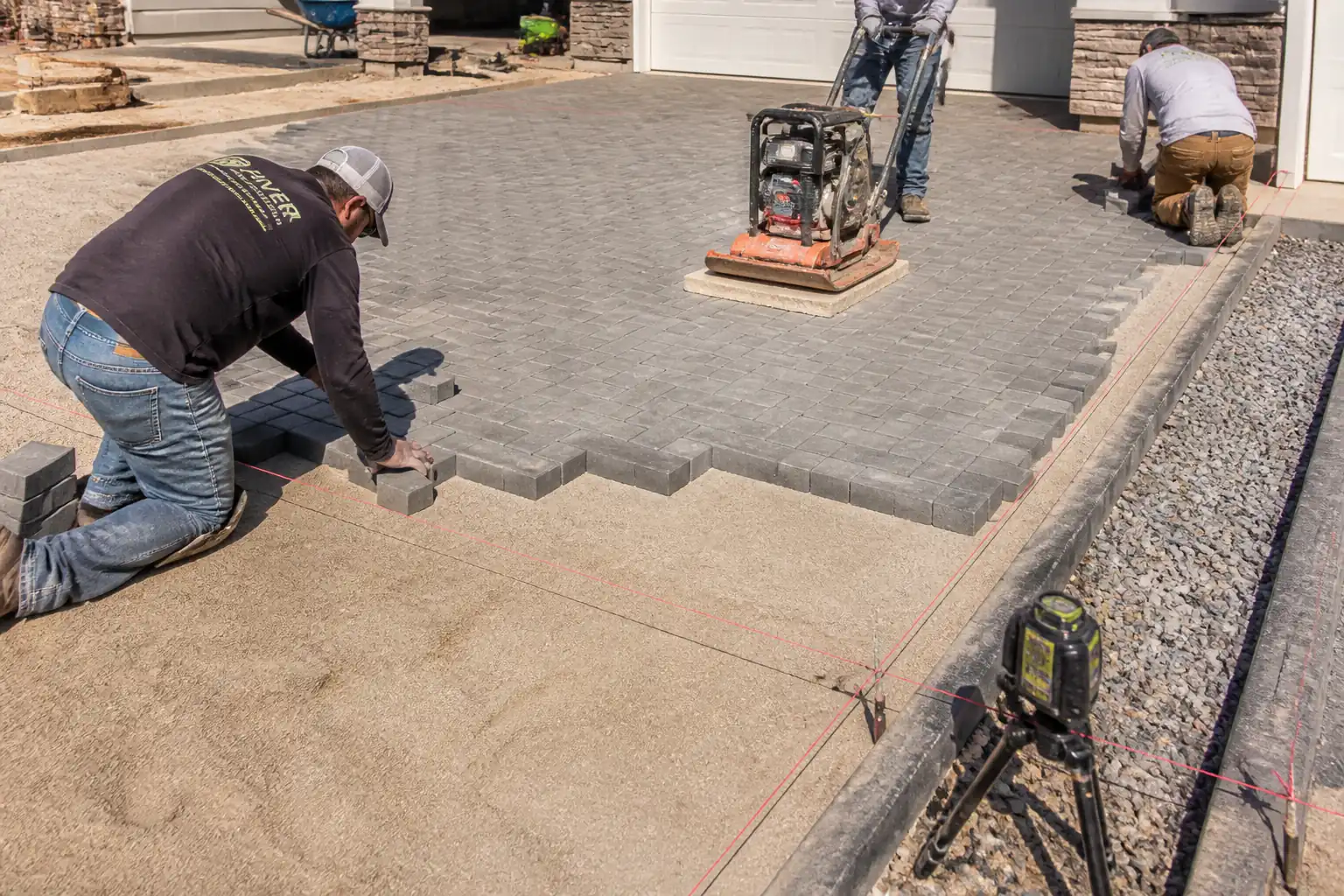
Permits and TMP, materials, formation compaction, concrete bedding/haunching, kerb line/level, joints, curing, and final acceptance.
Typical hold, witness, and review points
Permit to Dig (H), first 10 m kerb alignment (H), concrete slump (W), expansion joints (W), final survey (H).
Typical inspection records
Permits, IRs, delivery tickets, slump sheets, cube results, density tests, check sheets, as-built survey, photos.
Important approval note
This ITP is an AI-assisted editable starting point, not a pre-approved document. Before use on any project, all inspection activities, hold points, and acceptance criteria must be reviewed and approved by the relevant parties (superintendent, principal contractor, or client representative) in accordance with your contract and project quality plan.
Always verify acceptance criteria against your applicable drawings, specifications, and regulatory requirements. Hold points must be confirmed with the relevant authority before work proceeds past that point.
Inspection and test plan
| Activity | Inspection / Test | Acceptance Criteria | Responsibility | Record |
|---|---|---|---|---|
| Pre-works permits and TMP | Permits verified; TMP in place | Approved Permit to Dig; approved TMP implemented. | PM / HSE / Engineer | Permits, TMP checklist |
| Materials – kerbs and joint filler | Visual/dimensions; certs | Conform to BS EN 1340; filler per ASTM D1751/EN 14188 compatibility. | QA/QC | IR, delivery tickets, DoP/CoC |
| Formation preparation/compaction | In-situ density | ≥95% MDD or as specified. | QA/QC / Foreman | Density test reports, IR |
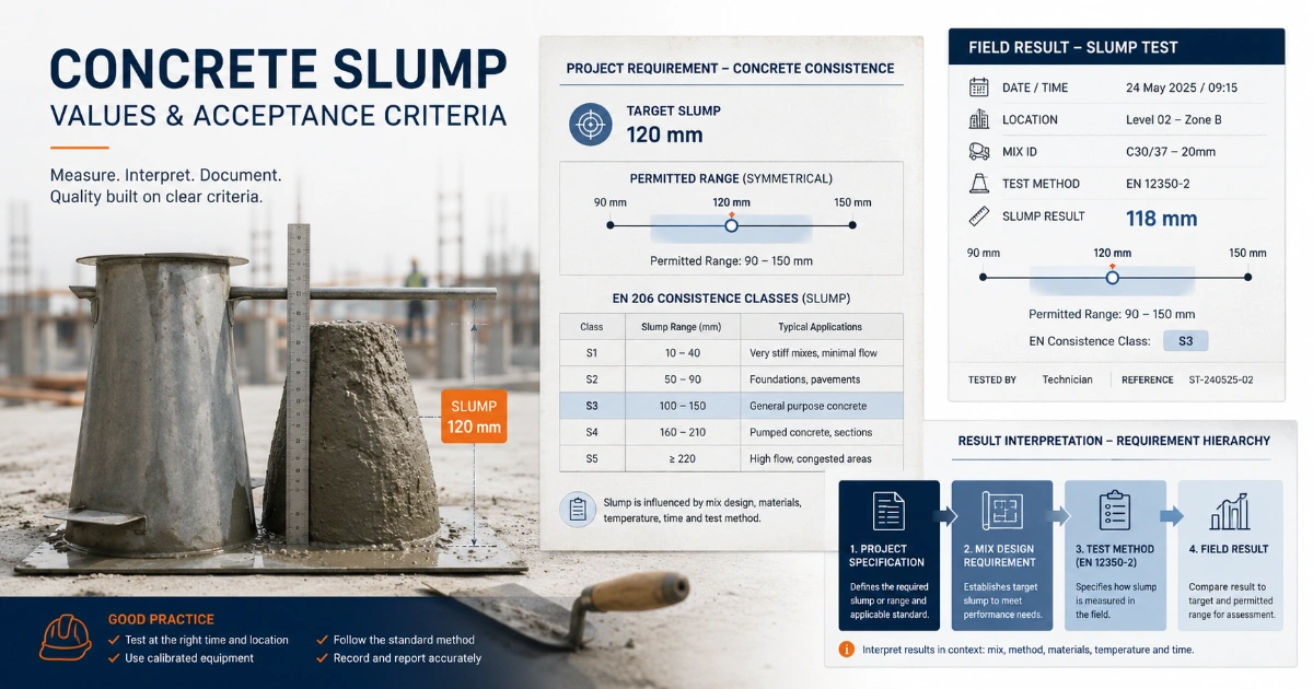
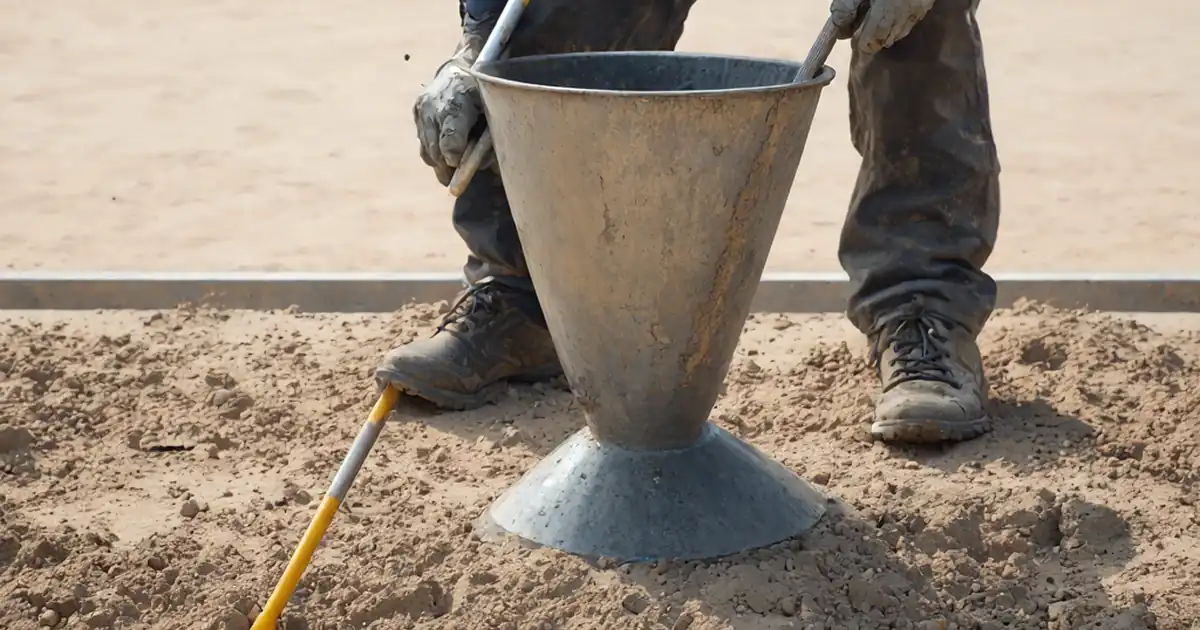
| Concrete bedding – delivery and slump | Slump, temperature | Slump S3 (100–150 mm); temperature 5–30°C [Verify]. | Materials Eng. / QA/QC | Slump sheets, tickets |
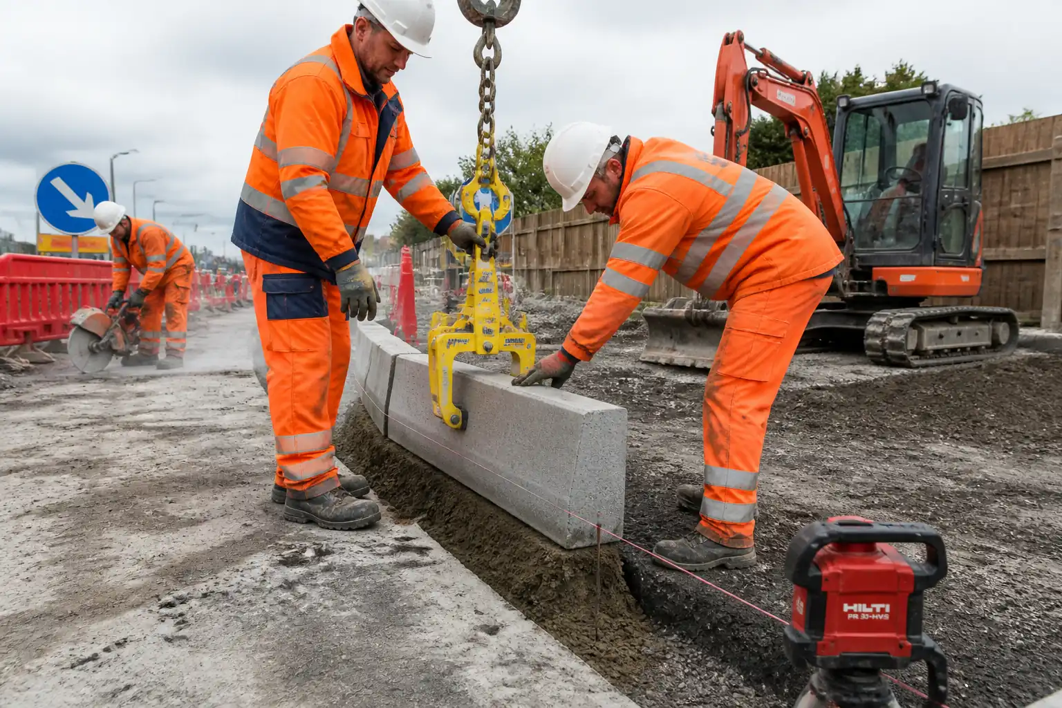
| Kerb placement – initial section | Line, level, upstand, joints | Line ±10 mm/10 m; level ±6 mm; upstand ±5 mm; joint 2–5 mm. | Engineer / QA/QC | IR, check sheet |
| Expansion/movement joints | Spacing, thickness, continuity | 10–20 mm filler; spacing 10–20 m and at returns; full-depth. | QA/QC | IR, photos |
| Back-haunching concrete | Dimensions, continuity | Thickness ≥150 mm; 2/3–3/4 height; neat, void-free. | QA/QC | IR, photos |
| Concrete curing and protection | Curing method check | Curing applied for ≥48 h or per spec; protected from early traffic. | Foreman / QA/QC | Diary, photos |
| Final alignment and level survey | Survey/straightedge | All tolerances achieved; defects rectified. | Engineer / QA/QC | As-built, IR, punch list closeout |
This table is a read-only public reference. Download the PDF or Excel version, or customize this ITP to edit it for your project.
Frequently asked questions
Related method statement
This Inspection and Test Plan is associated with the Method Statement: Installation of Precast Concrete Kerbs and Flush Edgings method statement, which describes the step-by-step construction sequence, resources, materials, equipment, safety controls, and environmental controls for this activity.
View the Method Statement: Installation of Precast Concrete Kerbs and Flush Edgings method statement →Continue with related inspection, method statement, article, and checklist resources.