
Method Statement: Titanium-Zinc Roll-Cap Architectural Roofing Installation – Method Statement
AI-assisted method statement with matching ITP, PDF download, and Excel export.
More than a static template
Unlike a downloadable Word or PDF template, this method statement is an AI-assisted editable starting point connected directly to a matching Inspection and Test Plan. Every section is structured, project-adaptable, and ready to export.
- AI-assisted drafting — Customize every section with AI for your specific project scope.
- Linked ITP — A matching inspection and test plan is generated alongside the method statement.
- Multiple export formats — Download as a formatted PDF or editable Excel spreadsheet.
- Editable starting point, not a final document — Review, verify, and adjust all content against your project requirements before use.
Static template vs. Quollnet workflow
| Feature | Static template | Quollnet |
|---|---|---|
| Project-specific content | Manual fill-in required | AI-assisted customization |
| Linked ITP | Separate document, no link | Matching ITP included |
| Export formats | Usually PDF only | PDF and Excel |
| Structured sections | Free-form layout | 13 standardized sections |
| Saved to your account | Local file only | Cloud-saved, reusable |
| Content accuracy | You verify everything | AI-assisted, you still verify |
| Cost | Often free but time-intensive | Free to customize and download |
What you can customize
When you save this method statement to your account, every section becomes editable. The following 13 sections are included:
- Scope — Defines the activity and its boundaries.
- References — Standards, specifications, and drawings.
- Responsibilities — Roles and accountabilities.
- Resources — Labour, plant, and equipment summary.
- Materials — Materials and compliance requirements.
- Equipment — Tools and equipment details.
- Prerequisites — Hold points and pre-conditions.
- Method sequence — Step-by-step construction sequence.
- Safety controls — HSE risk controls and PPE.
- Environmental controls — Environmental mitigation measures.
- QA/QC — Quality inspection and test requirements.
- ITP — Inspection and Test Plan table (has its own page).
- Attachments — Referenced drawings and documentation.
Why this method statement is used
This method statement is used to define and communicate the approved procedure for carrying out method statement: titanium-zinc roll-cap architectural roofing installation on site. It ensures the work is planned in advance, the correct resources and controls are in place, and all personnel understand responsibilities, sequence, quality requirements, and safety controls before work begins. It aligns site execution with the documented scope and acceptance expectations.
Who uses this method statement
This method statement is used by contractors, site supervisors, project engineers, QA/QC engineers, HSE officers, consultants, and client representatives. It serves as a shared reference for planning, execution, supervision, inspection, and approval of the activity on site.
When it is prepared and submitted
The method statement is prepared before the work activity starts and submitted as part of the pre-construction documentation package for review and approval.
Who reviews or approves it
The method statement is usually submitted to the client representative, consultant, resident engineer, or project management consultant for review and approval before the work commences.
Important approval note
This method statement is an AI-assisted editable starting point, not a pre-approved document. Before use on any project, all content must be reviewed and approved by the relevant parties (superintendent, principal contractor, or client representative) in accordance with your contract and project quality plan.
For example: if your specification requires a departure from a referenced standard, that departure must be documented and approved separately — this method statement will not capture that automatically. Always verify against your applicable drawings, specifications, and regulatory requirements.
Method statement content
Scope
Overview
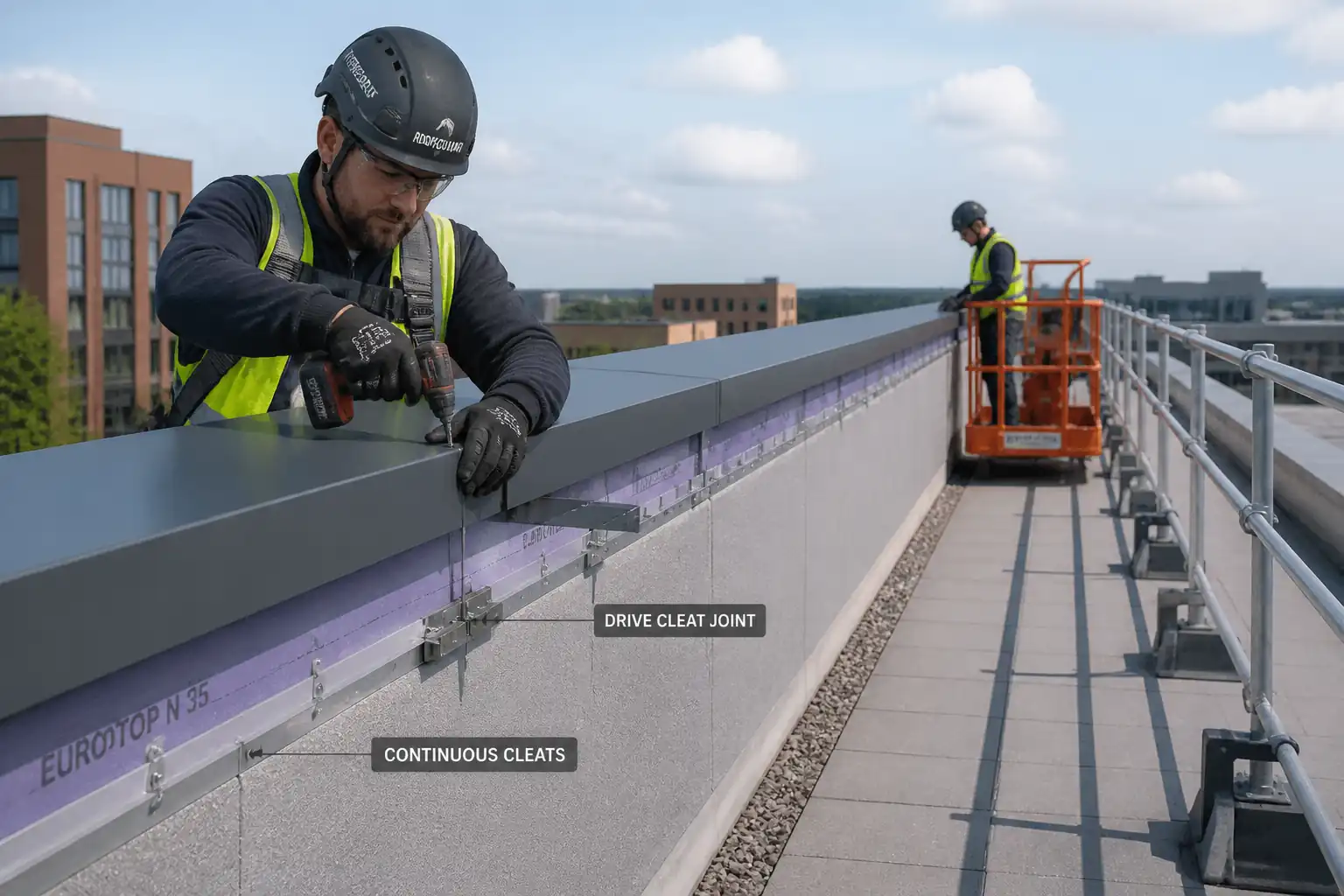
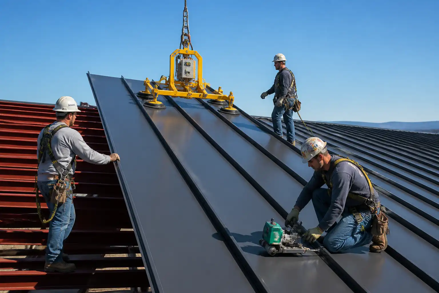
This method statement covers supply, fabrication, and installation of titanium-zinc roll-cap roofing on pitched roofs, including:
- Substrate preparation and installation of ventilation layer(s) and separation layers
- Panel/tray profiling from titanium-zinc coil/sheet
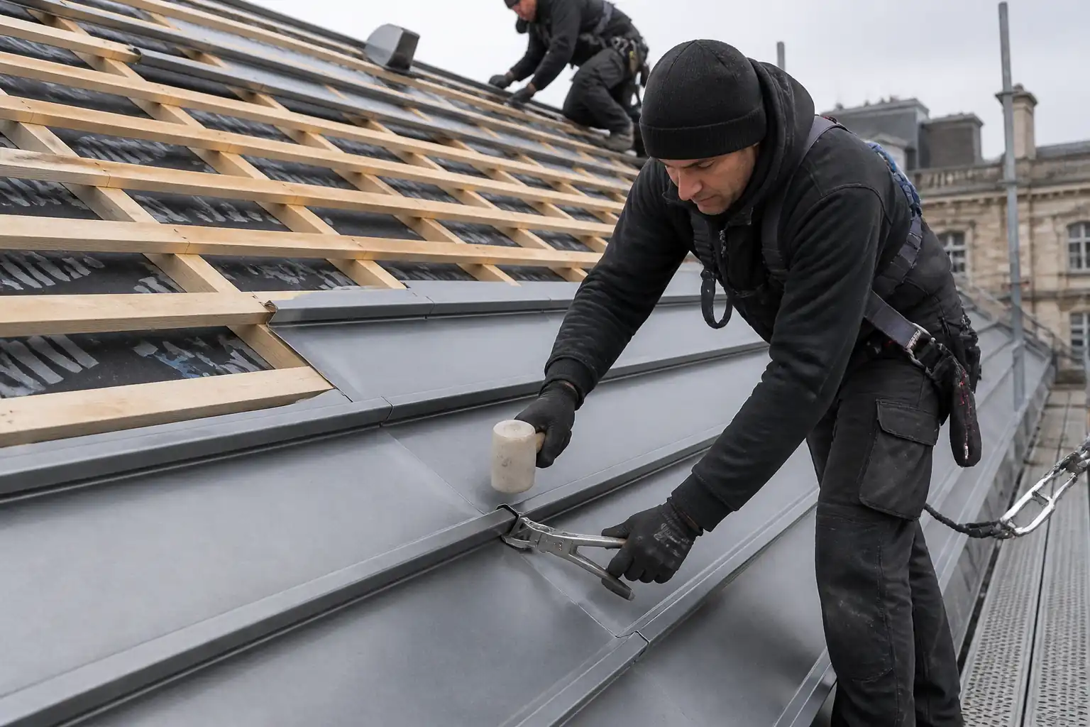
- Roll-cap (batten cap) formation, hand-tool folding, and mechanical fixing with fixed/sliding clips
- Junctions at eaves, ridge, hips, valleys, penetrations, and abutments
- Expansion joint design and installation to accommodate thermal movement
- Quality assurance, inspection and testing, and handover documentation
Exclusions
- Primary roof structure design and installation
- Permanent access systems and fall protection (specified separately)
- Rainwater goods beyond interface flashings
Key Performance Requirements
- Weather-tightness with controlled ventilation to manage condensation
- Movement accommodation without oil-canning or buckling
- Compatibility of all contacting materials with titanium-zinc
- Visual quality consistent with architectural finish requirements
Constraints
- Minimum finished roof pitch for zinc roll-cap: typically ≥7° (≈1:8) with continuous underlay and properly detailed caps [Verify per manufacturer and project specifications]
- Maximum tray length without intermediate expansion joint: typically 6–10 m depending on detailing and clip strategy [Verify per manufacturer and project specifications]
- Thermal expansion coefficient (zinc): approximately 22 × 10^-6 /K. Expansion allowance to be calculated per tray length and site ΔT.
References
| Document Type | Reference / Number | Revision | Notes |
|---|---|---|---|
| Standard | EN 988 – Zinc and zinc alloys — Specifications for rolled flat products for building | Material compliance for titanium-zinc coil/sheet. | |
| Standard | EN 14783 – Metal sheet and strip for building — Self-supporting products — Product specification and requirements | Performance and product requirements for metal roofing and cladding. | |
| Standard | ASTM B69 – Standard Specification for Rolled Zinc | Alternative material specification for rolled zinc products (where ASTM is adopted). | |
| Standard | EN 1991-1-3/1-4 – Eurocode actions on structures (snow/wind) | Basis for clip spacing and fixing strategy per wind/snow loads [Verify per project structural design]. | |
| Standard | ISO 12944 – Paints and varnishes — Corrosion protection of steel structures by protective paint systems | For any painted steel interfaces or temporary protection (if applicable). | |
| Best Practice/Manufacturer | VMZINC / RHEINZINK technical manuals for roll/batten cap roofing | Detailing, clip types, separation layers, and soldering recommendations [Verify against chosen manufacturer]. | |
| Standard | ISO 18084 (EN 13859-1 context) – Underlays for roofing (breather membranes) | Properties and installation of underlays/breather membranes. | |
| HSE Guidance | Local Work at Height Regulations; EN 365, EN 795 (fall protection) [Verify per local jurisdiction] | Requirements for safe access and fall arrest/edge protection. |
Responsibilities
| Role | Responsibility | Name / Party |
|---|---|---|
| Main Contractor Site Manager | Prepare method statement, coordinate design interfaces, approve shop drawings, manage inspections and ITP. | Main Contractor |
| General Contractor/Builder | Provide structural substrate readiness, confirm moisture content and tolerances, provide access/edge protection. | GC |
| Specialist Zinc Roofing Subcontractor | Detail zinc system, provide material certifications, fabricate panels, install roofing, complete QA/QC records. | Subcontractor |
| Consultant/Engineer’s Representative | Verify compliance at hold/witness points, review material certs, sign ITP. | Engineer |
| HSE Officer | Implement task-specific RAMS, conduct toolbox talks, monitor permits, verify PPE and fall protection. | Contractor |
| Plant/Tools Supervisor | Calibrate tools, maintain equipment, ensure guards, maintain hot-work controls. | Contractor |
Resources
| Resource Type | Description | Quantity | Remarks |
|---|---|---|---|
| Skilled labor | 1–2 per crew [Verify] | Experienced with roll-cap systems. | |
| Skilled labor | 2–4 per crew [Verify] | Panel forming, hand folding, soldering certified. | |
| Labor | 1–2 per crew | Material handling, housekeeping, spotter for lifting. | |
| HSE | As per site risk profile |
Materials
| Material | Specification / Grade | Quantity | Remarks |
|---|---|---|---|
| Titanium-zinc coil/sheet | Compliant with EN 988 or ASTM B69; supplier: VMZINC/RHEINZINK or approved equivalent; batch certs required. | ||
| Timber substrate (plywood/boards) and roll battens | Min 18–21 mm plywood sheathing; battens nominal 40×60 to 50×70 mm dressed, straight, Class 2 treated [Verify]. | ||
| Breather/underlay membrane | Waterproof, vapor-permeable, UV-stable; lap tapes compatible with zinc. | ||
| Structured ventilating separation layer (3–10 mm) | 3D entangled mesh or needlefelt mat providing drainage/ventilation; fire classification per project [Verify]. | ||
| Stainless steel clips and screws | A2/A4 stainless steel; clip thickness 0.5–0.6 mm; spacing typically 200–330 mm c/c [Verify by wind calc]. | ||
| Butyl sealant tapes and compatible sealants | Non-acidic, zinc-compatible, solvent-free; service temp per climate. | ||
| Soft solder and flux for zinc | SnCu or SnAgCu solder; flux per ISO 9454 type for zinc; soldering 250–300°C [Verify]. | ||
| Insect mesh and eaves/ridge ventilation components | Non-ferrous/stainless mesh; free area per design [Verify]. |
Equipment
| Equipment | Capacity / Type | Quantity | Inspection Required |
|---|---|---|---|
| Portable folding/hemming tools, seaming pliers, nylon mallets, snips | Hand tools for roll-cap formation; profiles 40–60 mm [Verify]. | Daily check | |
| Bench shear/guillotine and profiling brake | For cutting/forming trays and caps; maintain clean edges. | Guarding and calibration check weekly | |
| Soldering irons/gas torches/hot-air tools | 250–350 W irons or propane torches with fine control; temp 250–300°C. | Hot work permit; leak test daily | |
| Cordless screwdrivers/drivers with torque control | For stainless fixings; torque settings per fastener data. | Battery/bit condition daily | |
| Scaffolding, edge protection, fall arrest systems | EN 13374 or equivalent; lifelines EN 795. | Weekly scaffold tags; pre-use checks | |
| Lifting aids/rope & wheel, material hoists | Coils up to 200–300 kg [Verify]. | LOLER/Statutory inspection valid |
Prerequisites
Approvals and Documents
- Approved shop drawings, setting-out drawings, clip schedules, and wind load calculations
- Material data sheets and certificates of conformity (EN 988/ASTM B69)
- Method Statement, ITP, and task-specific Risk Assessment approved
- Hot work permit (if soldering), Work at Height permit, lifting plan [Verify per project HSE plan]
Site Readiness
- Substrate installed, dry, and within tolerance: flatness ±3 mm over 2 m straightedge [Verify]
- Timber moisture content ≤18% (record actual readings)
- Confirm ventilation path continuity from eaves to ridge; vent components on site
- Access, scaffolding, and edge protection erected and inspected
- Weather conditions: do not install zinc below 5°C for soldering or in precipitation; protect against wind uplift during installation
Mock-Up
- Construct and approve a representative bay mock-up including roll-cap, eave, ridge, and an abutment before main works. Use as benchmark for workmanship and tolerances.
Method Sequence
| Step | Activity | Description | Responsibility | Inspection / Hold Point |
|---|---|---|---|---|
| 1 | Pre-start verification and setting out | Confirm roof pitch, tray layout, and roll-cap centers. Set control lines from eaves to ridge. Calculate tray lengths and thermal allowance ΔL=α·L·ΔT. Mark anchor (fixed clip) zone at eaves (typically first 1–2 m) [Verify]. | Subcontractor Supervisor | ITP Hold: Layout approval |
| 2 | Install breather/underlay membrane | Lay membrane over timber substrate parallel to eaves. Provide horizontal laps ≥100 mm and vertical laps ≥150 mm; tape per manufacturer. Turn up at abutments ≥100 mm. Do not trap water. Provide continuous eaves and ridge ventilation pathways with insect mesh. | Installer | Witness |
| 3 | Install structured ventilating separation layer | Place 3–10 mm 3D mat or needlefelt separation layer over membrane. Butt joints tightly; stagger joints. Terminate neatly at edges; maintain air gap continuity. Fix lightly with stainless staples as required without compressing the void. | Installer | Witness |
| 4 | Install roll battens (caps base) | Fix straight, dressed timber battens (e.g., 40×60 to 50×70 mm) parallel to fall at designed centers (tray width typically 430–600 mm). Secure to substrate per design using stainless or coated fixings. Ensure batten top line is uniform; shim as needed. | Installer | Hold |
| 5 | Fabricate trays and caps | From EN 988 titanium-zinc coil, cut trays to length with allowance for hems and end folds. Pre-form side upstands to engage roll battens (typ. 25–35 mm) and hems/drips at eaves. Form separate cap strips sized to cover battens with final cap height 40–60 mm after locking [Verify]. Deburr edges; avoid overheating or contamination. | Sheet Metal Worker | Witness |
| 6 | Install fixed and sliding clips | At anchor zone (eaves), install fixed clips both sides of each tray at spacing per wind calc (typ. 200–250 mm c/c). Beyond anchor zone to ridge, install sliding clips permitting movement (slot orientation downslope). Use A2/A4 stainless clips and screws into sound timber per manufacturer torque guidance. | Installer | Hold |
| 7 | Place trays and engage with battens and clips | Position tray between battens; engage tray edges with clips. Dress side upstands tight against battens using nylon mallet and seaming pliers. Ensure trays are free to expand upward from anchor zone; verify no pinch points. | Installer | Witness |
| 8 | Form and fix roll caps | Place pre-formed zinc cap over timber roll. Lock edges to tray upstands using hand seamers to achieve uniform cap height (40–60 mm). Provide end folds/anti-capillary details at cap ends and intersections. Where specified, include butyl tape under caps at exposed ridges or low pitches [Verify]. | Sheet Metal Worker | Witness |
| 9 | Eaves, ridge, hip, valley, and abutment detailing | Install drip edges at eaves with minimum 50 mm drip projection [Verify]. Ridge details to maintain through-vent with mesh; provide ridge caps with movement joints as required. At abutments, turn upstand ≥150 mm behind wall flashing with welt; allow sliding. Form valleys with widened trays and splash folds; ensure water flow priority and anti-capillary folds. | Lead Installer | Hold (first-of-kind) then Witness |
| 10 | Penetrations and collars | Template and form sleeves/collars for pipes, vents, and skylights. Provide expansion collars and flexible interfaces (EPDM gaskets) to avoid galvanic contact. Lock or solder as detailed. Maintain min 100 mm cover and 150 mm upstands around curbs [Verify]. | Sheet Metal Worker | Witness |
| 11 | Soldering (where specified) | Clean surfaces mechanically; apply zinc-compatible flux. Heat evenly to 250–300°C; apply Sn-based solder to form continuous fillet. Avoid overheating and burn-through. Neutralize and remove flux residues; rinse with clean water; dry surfaces. | Certified Solderer | Witness |
| 12 | Expansion joints | Where tray length exceeds allowable without joints, install proprietary expansion joint profiles or intermediate roll-breaks. Detail sliding connections at abutments and ridge. Provide clear movement gaps per calculated ΔL; do not seal solidly across joints. | Lead Installer/Engineer | Hold |
| 13 | Cleaning and protection | Remove swarf, flux residues, and debris. Do not use abrasive cleaners. Install temporary protection and rain-shedding measures if adjacent works ongoing. Record any touch-ups per manufacturer guidance. | Installer | Witness |
| 14 | Final inspection and handover | Walk-over inspection from safe access; verify clip fixity (sample checks), seam integrity, ventilation continuity, and junctions. Provide O&M manuals, warranties, and as-built drawings. Optional local hose testing at selected details if agreed [Verify]. | Subcontractor & Engineer | Hold (Final) |
Safety Controls
Task-Specific HSE Controls
- Hazard: Work at height (falls from edges, through fragile surfaces)
- Likely consequence: Serious injury or fatality
- Engineering/procedural control: Install compliant edge protection (EN 13374) and guardrails; use full-body harness with lifelines (EN 361/EN 795) where guardrails absent; designate access routes; keep roof clear of trip hazards; weather monitoring with wind thresholds [Verify per project HSE plan and local regulations].
- Required PPE: Harness and lanyard, safety helmet with chinstrap, non-slip safety footwear, cut-resistant gloves
- Collective preventive measure: Perimeter guardrails, scaffold working platforms, safety nets where feasible
-
Inspection/permit/supervision: Scaffold tagged weekly; pre-use harness checks; Work at Height permit; supervisor to monitor wind speeds and stop work above agreed limits
-
Hazard: Manual handling of zinc coils/sheets and timber rolls
- Likely consequence: Musculoskeletal injuries, crush injuries
- Engineering/procedural control: Use mechanical lifts/hoists; team lifts with weight assessment; break down coils where possible; use coil trolleys and sheet carriers; enforce clear lifting plans
- Required PPE: Grip gloves, safety boots, back support (as required)
- Collective preventive measure: Designated lifting zones; exclusion of non-essential personnel during lifts
-
Inspection/permit/supervision: Lifting equipment inspection certificates; lifting supervisor/appointed person control
-
Hazard: Sharp edges and cutting operations
- Likely consequence: Lacerations
- Engineering/procedural control: Use guarded shears/guillotines; deburr edges; implement cut-resistant glove policy; store sheets vertically with spacers
- Required PPE: Cut-resistant gloves (Level C or better), long sleeves, eye protection
- Collective preventive measure: Tool guards and designated cutting area
-
Inspection/permit/supervision: Daily tool condition checks; supervision sign-off for new operatives
-
Hazard: Hot works (soldering/torch use)
- Likely consequence: Burns, fire, fume inhalation
- Engineering/procedural control: Hot work permit; fire blankets/shields; non-combustible workspace; use temperature-controlled irons; maintain 60-min fire watch post-works; ensure flux compatibility; avoid enclosed fume accumulation; have Class A/B fire extinguishers at position
- Required PPE: Heat-resistant gloves, eye protection, long sleeves, respiratory protection if in semi-enclosed area [Verify]
- Collective preventive measure: Fire-resistant barriers and extinguishers staged; local ventilation
-
Inspection/permit/supervision: Calibrated gas regulators; leak checks with soapy water; hot-work permit signed by HSE
-
Hazard: Slips/trips on inclined roof and loose materials
- Likely consequence: Falls, strains
- Engineering/procedural control: Use roof ladders/crawling boards; maintain housekeeping; secure tools/materials against sliding; no work on wet/frosted surfaces
- Required PPE: Non-slip footwear, gloves
- Collective preventive measure: Staging of materials; toe boards on platforms
-
Inspection/permit/supervision: Supervisor checks at start/end of shift
-
Hazard: Adverse weather (wind uplift of sheets)
- Likely consequence: Loss of control of sheets, impact injuries, falls
- Engineering/procedural control: Establish wind speed stop-work limits (e.g., ≥12–15 m/s for sheet handling [Verify]); secure partially fixed trays; postpone lifts in gusty conditions
- Required PPE: Standard PPE
- Collective preventive measure: Temporary fixings and restraints for stored sheets
-
Inspection/permit/supervision: Weather monitoring log; supervisor authorization
-
Hazard: Noise and vibration from cutting/forming
- Likely consequence: Hearing damage
- Engineering/procedural control: Use low-noise tools where possible; limit exposure duration; implement hearing protection zones
- Required PPE: Hearing protection (EN 352)
- Collective preventive measure: Acoustic screens if feasible
-
Inspection/permit/supervision: Noise assessments as required
-
Hazard: Chemical incompatibility/galvanic contact (e.g., copper contact or runoff onto zinc)
- Likely consequence: Accelerated corrosion, premature failure
- Engineering/procedural control: Material segregation; install isolation gaskets (EPDM/PE); reroute dissimilar metal runoff; verify sealant/adhesive compatibility with zinc
- Required PPE: Standard PPE when handling sealants/chemicals
- Collective preventive measure: Prestart materials compatibility review
-
Inspection/permit/supervision: Submittal approval and site verification by QA/QC
-
Hazard: Access/egress and rescue
- Likely consequence: Delayed emergency response
- Engineering/procedural control: Rescue plan for suspended worker; clear access routes; first aiders on site
- Required PPE: As above
- Collective preventive measure: Dedicated rescue kit at roof level
- Inspection/permit/supervision: Drill/briefing prior to works
Environmental Controls
Controls for Environmental Protection
- Metal swarf and debris
- Risk: Gutters/drains blockage; staining
-
Control: Use magnetic/brush cleanup every lift; prohibit grinding; collect and dispose in metal recycling stream
-
Flux and solder residues
- Risk: Surface staining; contaminated runoff
-
Control: Use zinc-approved flux sparingly; immediately neutralize and wipe; prevent wash-off to drains; contain wipes as hazardous waste if applicable [Verify per local regulations]
-
Runoff management and dissimilar metal contamination
- Risk: Galvanic acceleration by copper/aluminum runoff onto zinc
-
Control: Reroute higher-nobility metal runoff; install isolation and drip breaks; document roof metals map in as-builts
-
Noise and working hours
- Risk: Nuisance to neighbors
-
Control: Schedule high-noise cutting during permitted hours; use quieter tooling; maintain equipment
-
Timber dust and offcuts
- Risk: Airborne dust, clogging drains
-
Control: Cut in designated area with extraction where feasible; bag and dispose; prevent dust migration to roof drains
-
Waste segregation
- Risk: Landfill burden
-
Control: Segregate zinc (100% recyclable), timber, membranes, and general waste; record tonnages
-
Weather protection of materials
- Risk: White rust on zinc from trapped moisture
- Control: Store coils/sheets dry and ventilated; avoid plastic wraps in sun; elevate off ground; FIFO stock rotation
QA/QC
Quality Assurance Plan
- Submittals: Certificates of conformity for EN 988/ASTM B69; MSDS for flux/chemicals; shop drawings; wind load clip calculations; mock-up plan
- Calibration: Verify temperature control on soldering tools; maintain measuring tapes and levels; torque settings for drivers
- Training/Competency: Zinc installers certified/experienced in roll-cap systems; solderers competent for zinc soft soldering; toolbox talks on compatibility and handling
Inspection and Testing
- Substrate: Moisture content logs (≤18%); flatness survey ±3 mm over 2 m [Verify]
- Membranes: Laps and continuity checks each lift; tape adhesion spot check 1 per 50 m of seam [Verify]
- Separation Layer: 100% coverage verification; no compression at edges
- Clip Spacing: Verify against calculation; sample check at least every 10 m of eaves line and at each slope change
- Seam and Cap: Measure cap height (target 40–60 mm, ±5 mm); check straightness with stringline; no visible gaps
- Junctions: Check upstands ≥150 mm; ridge/eaves ventilation continuity; drip projections ≥50 mm [Verify]
- Soldered Joints: Visual continuity; no pinholes; wipe/neutralize flux; sample peel test on offcut if required
- Movement: Confirm sliding at clips manually before locking caps
Acceptance Criteria
- Materials comply with EN 988/ASTM B69 and approved finishes
- All ITP hold/witness points closed with records
- No leaks on localized hose test of selected details if specified [Verify]; otherwise visual inspection only to avoid staining
- Visual appearance: uniform lines; oil-canning within agreed architectural tolerance
Records
- ITP with signatures, daily inspection checklists, moisture logs, clip spacing log, mock-up approval, hot-work permits, as-built drawings, warranties and O&M manuals
Attachments
Attachments (to be appended)
- Manufacturer’s technical manuals and detail sheets for selected zinc supplier
- Shop drawings and setting-out layouts including tray widths and roll spacing
- Clip schedule with wind load calculations and anchor/sliding zones marked
- Typical details: eaves drip, ridge with ventilation, hip, valley, abutment to wall/chimney, penetration collars, expansion joint profile
- Hot work permit template and soldering procedure including flux MSDS
- Daily inspection checklists (substrate moisture log, membrane checklist, clip spacing log, seam/cap measurements)
- O&M manual outline and maintenance instructions
This content is a read-only public reference. Download or customize to get an editable version.
ITP preview
The first inspection activities from the linked ITP for Method Statement: Titanium-Zinc Roll-Cap Architectural Roofing Installation:
| Activity | Inspection / Test | Acceptance Criteria | Responsibility | Record |
|---|---|---|---|---|
| Material delivery and certification | Verify EN 988/ASTM B69 certificates, batch numbers, finishes | Certificates match delivery; finishes per submittal; no transport damage | Subcontractor / Engineer (Review) | Material inspection report & certs |
| Substrate readiness | Moisture content measurement; flatness survey; fastener pull-out test if required | Moisture ≤18%; flatness ±3 mm over 2 m; pull-out ≥ design value [Verify] | GC / Subcontractor / Engineer | Substrate acceptance form |
| Underlay membrane installation | Check laps, terminations, taped seams, vent path continuity | Laps ≥100/150 mm; taped per manufacturer; full continuity; no tears | Subcontractor / Engineer (Witness) | Membrane checklist & photos |
Showing 3 of 12 inspection activities. View full ITP →
Related Inspection and Test Plan
An Inspection and Test Plan (ITP) is available for Method Statement: Titanium-Zinc Roll-Cap Architectural Roofing Installation. The ITP defines the inspection activities, acceptance criteria, hold and witness points, responsible parties, and records required to verify the work described in this method statement.
View the Method Statement: Titanium-Zinc Roll-Cap Architectural Roofing Installation ITP →Frequently asked questions
Continue with related Quollnet resources connected to this method statement.