
Method Statement: Structural Backfill Behind Bridge Abutments and Wing Walls – Method Statement
AI-assisted method statement with matching ITP, PDF download, and Excel export.
More than a static template
Unlike a downloadable Word or PDF template, this method statement is an AI-assisted editable starting point connected directly to a matching Inspection and Test Plan. Every section is structured, project-adaptable, and ready to export.
- AI-assisted drafting — Customize every section with AI for your specific project scope.
- Linked ITP — A matching inspection and test plan is generated alongside the method statement.
- Multiple export formats — Download as a formatted PDF or editable Excel spreadsheet.
- Editable starting point, not a final document — Review, verify, and adjust all content against your project requirements before use.
Static template vs. Quollnet workflow
| Feature | Static template | Quollnet |
|---|---|---|
| Project-specific content | Manual fill-in required | AI-assisted customization |
| Linked ITP | Separate document, no link | Matching ITP included |
| Export formats | Usually PDF only | PDF and Excel |
| Structured sections | Free-form layout | 13 standardized sections |
| Saved to your account | Local file only | Cloud-saved, reusable |
| Content accuracy | You verify everything | AI-assisted, you still verify |
| Cost | Often free but time-intensive | Free to customize and download |
What you can customize
When you save this method statement to your account, every section becomes editable. The following 13 sections are included:
- Scope — Defines the activity and its boundaries.
- References — Standards, specifications, and drawings.
- Responsibilities — Roles and accountabilities.
- Resources — Labour, plant, and equipment summary.
- Materials — Materials and compliance requirements.
- Equipment — Tools and equipment details.
- Prerequisites — Hold points and pre-conditions.
- Method sequence — Step-by-step construction sequence.
- Safety controls — HSE risk controls and PPE.
- Environmental controls — Environmental mitigation measures.
- QA/QC — Quality inspection and test requirements.
- ITP — Inspection and Test Plan table (has its own page).
- Attachments — Referenced drawings and documentation.
Why this method statement is used
This method statement is used to define and communicate the approved procedure for carrying out method statement: structural backfill behind bridge abutments and wing walls on site. It ensures the work is planned in advance, the correct resources and controls are in place, and all personnel understand responsibilities, sequence, quality requirements, and safety controls before work begins. It aligns site execution with the documented scope and acceptance expectations.
Who uses this method statement
This method statement is used by contractors, site supervisors, project engineers, QA/QC engineers, HSE officers, consultants, and client representatives. It serves as a shared reference for planning, execution, supervision, inspection, and approval of the activity on site.
When it is prepared and submitted
The method statement is prepared before the work activity starts and submitted as part of the pre-construction documentation package for review and approval.
Who reviews or approves it
The method statement is usually submitted to the client representative, consultant, resident engineer, or project management consultant for review and approval before the work commences.
Important approval note
This method statement is an AI-assisted editable starting point, not a pre-approved document. Before use on any project, all content must be reviewed and approved by the relevant parties (superintendent, principal contractor, or client representative) in accordance with your contract and project quality plan.
For example: if your specification requires a departure from a referenced standard, that departure must be documented and approved separately — this method statement will not capture that automatically. Always verify against your applicable drawings, specifications, and regulatory requirements.
Method statement content
Scope
Overview
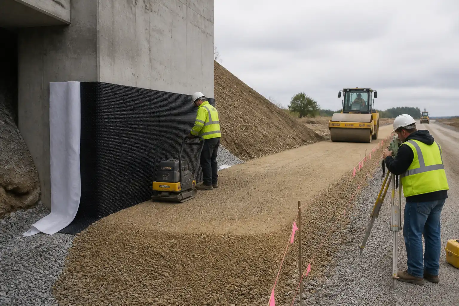
This method covers procurement, inspection, placement, and compaction of imported granular backfill behind bridge abutments and wing walls, including installation of geotextile separator and drainage geocomposite systems, subdrain pipes, protection boards (if specified), and survey control to achieve design lines/levels. It includes QA/QC controls for material certification, in-situ density, moisture, layer thickness, and finished level checks, with defined hold points to avoid differential settlement and hydrostatic pressure.
Extents
- Backfill zones directly behind reinforced concrete abutments and wing walls up to the underside of approach slab/pavement subbase.
- Lateral extent as shown on drawings, including returns at wing walls and transitions to embankment.
Exclusions
- Structural concrete works, waterproofing application on abutments (by others) except protection.
- Road pavement layers above the top of structural backfill (by others).
References
| Document Type | Reference / Number | Revision | Notes |
|---|---|---|---|
| Standard | BS 6031: Code of Practice for Earthworks [Verify applicability] | ||
| Standard | BS EN 1997 (Eurocode 7) & National Annex [Verify applicability] | ||
| Standard | BS EN 13285: Unbound mixtures; BS EN 13242: Aggregates for unbound and hydraulically bound materials [Verify applicability] | ||
| Standard | ASTM D1557 (Modified Proctor), ASTM D698 (Standard Proctor), ASTM D6938 (In-situ density by nuclear gauge) [Verify per project] | ||
| Standard | ASTM C136/C117 (Sieve/Fines), ASTM D4318 (Atterberg), ASTM C131/C535 (LA Abrasion) [Verify per project] | ||
| Standard | EN ISO 10319 (Tensile), EN ISO 12956 (AOS), ASTM D4491 (Permittivity) [Verify per project] | ||
| Standard | ASTM D4716 (Transmissivity), ASTM D1621/D6364 (Compression/Creep) [Verify per project] | ||
| Standard | AASHTO LRFD Bridge Construction Specifications (latest) [Verify applicability] |
Responsibilities
| Role | Responsibility | Name / Party |
|---|---|---|
| Project Manager | Project Manager | Contractor |
| Engineer | Site/Section Engineer | Contractor |
| QA/QC | QA/QC Engineer | Contractor |
| Surveyor | Land Surveyor | Contractor |
| HSE | HSE Officer | Contractor |
| Foreman | General Foreman | Contractor |
| Engineer/RE | Engineer/RE | Engineer |
Resources
| Resource Type | Description | Quantity | Remarks |
|---|---|---|---|
| Personnel | Foreman, 1; Site Engineer, 1; QA/QC tech, 1; Surveyor, 1; Compaction operators, 2; Excavator operator, 1; Labourers, 4–8 [Verify per workfront] | 10–14 | |
| Third-party | Independent/geotech laboratory for compaction curve, sieve, Atterberg, density, moisture | As required |
Materials
| Material | Specification / Grade | Quantity | Remarks |
|---|---|---|---|
| Granular fill | As per BOQ | Moisture-conditioned to OMC ± tolerances | |
| Geotextile | As required | Min overlap 300 mm | |
| Drainage geocomposite | As required | Provide compatible fixing accessories | |
| Pipe | As required | Rodent guard at outlet | |
| Protection board | As required |
Equipment
| Equipment | Capacity / Type | Quantity | Inspection Required |
|---|---|---|---|
| Roller | 1 | Yes | |
| Plate/rammer/mini-roller | As required | Yes | |
| Excavator/Loader | 1–2 | Yes | |
| Total station/Auto level | 1 set | Yes | |
| Nuclear gauge | 1 | Yes |
Prerequisites
- Approved method statement and ITP; shop drawings and details for geotextile/drainage and pipe outlets.
- Material approvals: COAs for granular fill, geotextile, drainage geocomposite, pipes; approved laboratory Proctor curve(s) per material type.
- Permits: Excavation/backfilling permit, lifting operations (if any), hot works (if cutting), working near traffic/rail/utility permits [Verify per project HSE plan and local regulations].
- Utilities cleared and marked; protection for any exposed services and abutment bearings.
- Subgrade prepared, trimmed, proof-rolled; waterproofing on wall cured and approved; weep holes clear.
- Drainage outlet locations and levels confirmed; outfalls and rodent guards available.
- Survey control established; benchmark verified; monitoring points on wall if required by designer.
- Weather check: no placement during heavy rain, freezing, or on saturated subgrade [Verify per spec].
- Equipment calibrated: nuclear gauge, survey instruments; plant prestart inspections completed.
- Prestart briefing/toolbox talk completed; task-specific risk assessment communicated.
Method Sequence
| Step | Activity | Description | Responsibility | Inspection / Hold Point |
|---|---|---|---|---|
| 1 | Pre-works inspection (Hold Point) | Joint inspection of subgrade, wall waterproofing, weep holes/outlets, survey control | Engineer/QA/QC/Site Eng. | IR submission |
| 2 | Install geotextile separator at formation | Place nonwoven geotextile on subgrade with 300–500 mm overlaps; anchor with pins/sandbags | Site Eng./Foreman | Visual |
| 3 | Fix drainage geocomposite to wall | Install vertical panels against wall over waterproofing; shingle laps downwards; secure with compatible fasteners; connect to weep holes/collector | Site Eng./Supplier rep | Visual |
| 4 | Install perforated collector pipe and outlet | Lay pipe at base with gradient ≥1% to outlet; wrap with geotextile or use sock; provide gravel surround if specified; fit rodent guard | Foreman/Plumber | Level check |
| 5 | Initial blinding/backing layer | Place first 150–200 mm loose thickness granular layer over geotextile; do not displace drainage | Foreman | Visual |
| 6 | Layered placement and compaction | Place subsequent lifts 150–200 mm loose; compact each lift to required density; moisture condition to OMC ± tolerance | Foreman/QA/QC | In-situ density & moisture |
| 7 | Near-wall compaction control | Within 1.0–1.5 m of wall, use plate compactors/rammers; no vibratory heavy roller; compact in thinner lifts (100–150 mm) | Foreman | Visual + density spot checks |
| 8 | Symmetrical build-up at abutment | Place and compact equally on both sides of abutment centerline/wing transitions to minimize differential lateral load | Foreman/Site Eng. | Sequence check |
| 9 | Intermediate level check | Survey after every 2–3 lifts or ~300–400 mm rise | Surveyor | Survey |
| 10 | Protect drainage and outlets | Install protection board if specified; ensure outlet screens/rodent guards fitted and visible | Foreman | Visual |
| 11 | Top of backfill preparation | Trim and level top surface for approach slab/subbase; maintain fall away from wall if specified | Site Eng./Surveyor | Survey |
| 12 | As-built and handover | Compile test results, approvals, as-built levels, material certs; demarcate buried drainage locations | QA/QC | Document review |
Health, Safety and Environment (HSE) - Safety Controls
Task-specific hazards and controls
- Hazard: Plant–personnel interface (rollers, excavators)
- Likely consequence: Crush injuries, struck-by incidents
- Engineering/procedural control: Segregated work zone with barriers; one-way plant routes; banksman for reversing; exclusion zone ≥5 m around operating plant
- Required PPE: Safety helmet, high-vis vest, steel-toe boots, gloves, eye protection
- Collective preventive measure: Physical barriers and spotters; audible alarms and beacons
-
Inspection/permit/supervision: Daily plant inspection checklist; competent operator certification; supervisor to enforce exclusion zones [Verify per project HSE plan and local regulations]
-
Hazard: Working at edge of abutment/embankment
- Likely consequence: Fall from height, vehicle rollover
- Engineering/procedural control: Edge protection (guardrails) or berms; stop blocks for plant; no tipping near edge; use short-reach equipment
- PPE: Same as above plus fall arrest if required near unprotected edges
- Collective measure: Temporary guardrails, toe boards
-
Inspection/permit/supervision: Prestart inspection of edge protection; permit to work near edges as applicable
-
Hazard: Wall/waterproofing damage and structural load effects
- Likely consequence: Water ingress, wall movement or damage
- Engineering/procedural control: Use light compaction within 1.0–1.5 m of wall; sequence symmetrically; install protection boards; prohibit plant contact with wall
- PPE: Standard
- Collective measure: Physical standoff markers from wall
-
Inspection/permit/supervision: Hold point before covering drainage; engineer to inspect if any cracking/movement observed
-
Hazard: Underground/embedded services at abutment toe/outlet crossings
- Likely consequence: Service strike, flooding, electrocution
- Engineering/procedural control: Utility scans and permits; trial holes; hand-dig within 1 m of known utilities; lock-out/tag-out for valves if needed
- PPE: Insulated gloves when applicable, standard PPE
- Collective measure: Utility plans displayed on site; color-coded markers
-
Inspection/permit/supervision: Utility clearance certificate; permit to dig
-
Hazard: Manual handling of geosynthetic rolls
- Likely consequence: Musculoskeletal injury, crush toes/fingers
- Engineering/procedural control: Use mechanical aids (spreader bars, trolleys); team lifts; follow weight limits
- PPE: Gloves with good grip, safety boots
- Collective measure: Lift plans for heavy rolls
-
Inspection/permit/supervision: Pre-lift briefing; equipment checks
-
Hazard: Dust and airborne particulates from dry fill
- Likely consequence: Respiratory irritation, visibility impairment
- Engineering/procedural control: Pre-wet material to moisture limits; water bowsers for suppression; limit drop heights
- PPE: FFP2/KN95 dust masks when dusty
- Collective measure: Speed limits to minimize dust
-
Inspection/permit/supervision: Environmental monitoring as required
-
Hazard: Noise and vibration from compaction
- Likely consequence: Hearing loss, nuisance, potential impact on adjacent structures
- Engineering/procedural control: Maintain distance from wall; select appropriate vibration settings; time restrictions
- PPE: Hearing protection (SNR per site rules)
- Collective measure: Acoustic alerting and signage
-
Inspection/permit/supervision: Noise/vibration monitoring if required by permit
-
Hazard: Confined space at weep holes/outlet tie-ins (if within chambers)
- Likely consequence: Asphyxiation, entrapment
- Engineering/procedural control: Confined space permit; gas testing; attendant and rescue plan
- PPE: Harness if required, gas monitor
- Collective measure: Tripod/winch where applicable
-
Inspection/permit/supervision: PTW with authorized gas tester
-
Hazard: Fuel/chemical spills from plant
- Likely consequence: Fire, soil/water contamination
- Engineering/procedural control: Drip trays; refuel in designated area; spill kits staged; no refueling near drains
- PPE: Nitrile gloves, eye protection
- Collective measure: Bunded storage for fuels
-
Inspection/permit/supervision: Weekly environmental inspections; spill log
-
Hazard: Adverse weather (rain/freezing)
- Likely consequence: Slips, loss of compaction quality, instability
- Engineering/procedural control: Suspend works during heavy rain/freeze; cover materials; reproof-roll after events
- PPE: Weather-appropriate PPE
- Collective measure: Gritting/anti-slip mats
- Inspection/permit/supervision: Supervisor authorization to resume after inspection
Note: Apply additional controls as required by project HSE plan and local regulations.
Environmental Controls
- Sediment control: Install silt fences or straw wattles downslope; keep stockpiles >10 m from watercourses; cover or wet down during wind.
- Runoff management: Grade to prevent runoff entering watercourses; use sumps; no discharge of turbid water without treatment; protect pipe outlets with riprap and screens.
- Noise/vibration: Schedule high-vibration compaction within permitted hours; maintain plant; monitor if near receptors [Verify per permit].
- Dust control: Maintain moisture near OMC; water bowser use; speed control ≤10 km/h on unpaved haul routes.
- Waste: Collect geotextile offcuts and packaging; segregate recyclables; dispose per waste management plan.
- Spill prevention: Bunded fuel storage; spill kits available; refuel >15 m from drains/watercourses where feasible.
- Material sourcing: Use approved quarries with legal permits; transport covered loads.
- Ecology/heritage: Stop work and notify if sensitive finds encountered.
- Carbon/efficiency: Optimize haul distances and compaction passes using test data to reduce fuel consumption.
Quality Assurance and Quality Control
Key acceptance criteria [Verify per project specifications]
- Material certification: COA for each delivery lot; test results for gradation, PI, LA Abrasion within specified limits.
- Proctor: One Modified Proctor (ASTM D1557) per material source change and at least every 2,500 m³.
- In-situ density: Minimum 95–98% of MDD per layer; frequency typically 1 test per 200–400 m² per lift or 1 per 50 m of wall length per lift, minimum 3 per lot.
- Moisture content: Within −2% to +1% of OMC unless otherwise specified.
- Layer thickness: 150–200 mm loose (100–150 mm within 1–1.5 m of wall); verify by probe/level.
- Levels and lines: Intermediate checks every ~300–400 mm rise; final level within ±10 mm; line within ±25 mm.
- Geotextile: Overlap ≥300 mm; no tears/holes; seams lapped in direction of fill placement; AOS/perm per approved data.
- Drainage geocomposite: Continuous coverage; laps ≥100 mm; shingle downward; no crushing; connectivity to outlet proven; transmissivity per approval.
- Collector pipe: Slope ≥1%; correct diameter/class; rods/screens fitted; outfall protected.
- Near-wall compaction: No heavy vibratory roller within 1.0–1.5 m of wall; use light equipment; monitor for wall distress.
Hold/Witness points
- Hold: Pre-cover inspection of drainage geocomposite and pipes.
- Hold: In-situ density/moisture results approval per lot before next lift.
- Hold: Final top-of-backfill level survey acceptance.
- Hold: Material approvals (fill, geotextile, geocomposite) prior to use.
Documentation
- ITP with signed IRs; lab reports; delivery tickets; calibration certs; survey records; as-built drawings showing drainage alignments.
Nonconformance and corrective action
- If density or moisture out of tolerance: Rework by re-compaction or reconditioning moisture; re-test.
- If geosynthetics damaged: Replace with patch extending ≥300 mm around defect; re-inspect.
- If levels out of tolerance: Trim/add material and re-compact; re-survey.
Calibration and competence
- Nuclear gauge current calibration and operator license; survey instruments within calibration period; operators trained/competent.
Attachments
- Typical detail: Geotextile and drainage geocomposite arrangement at abutment face and pipe outlet (manufacturer’s detail).
- Compaction pattern sketch showing exclusion zone near wall and pass counts.
- Sample ITP/IR forms and test request template.
- Material submittals: COAs and datasheets for fill, geotextile, drainage geocomposite, pipes.
- Calibration certificates for nuclear gauge and survey equipment.
- Risk assessment and toolbox talk record for this activity.
- As-built survey template and example.
This content is a read-only public reference. Download or customize to get an editable version.
ITP preview
The first inspection activities from the linked ITP for Method Statement: Structural Backfill Behind Bridge Abutments and Wing Walls:
| Activity | Inspection / Test | Acceptance Criteria | Responsibility | Record |
|---|---|---|---|---|
| Material approval – granular fill | Review COA; Gradation (ASTM C136/C117); PI (ASTM D4318); LA Abrasion (ASTM C131/C535) | Within specified limits; source approved prior to use. Hold Point. | QA/QC Engineer / Engineer | Material approval, lab reports |
| Material approval – geotextile & drainage geocomposite | Datasheets & certs; AOS (EN ISO 12956); Permittivity (ASTM D4491); Tensile (EN ISO 10319); Transmissivity (ASTM D4716) | Meets approved submittal and spec. Hold Point. | QA/QC Engineer / Engineer | Approvals, certs |
| Subgrade inspection & proof-rolling | Visual + proof-roll | Stable, dry, trimmed; defects rectified before placing. Hold Point. | Site Engineer / Engineer | IR, photos |
Showing 3 of 11 inspection activities. View full ITP →
Related Inspection and Test Plan
An Inspection and Test Plan (ITP) is available for Method Statement: Structural Backfill Behind Bridge Abutments and Wing Walls. The ITP defines the inspection activities, acceptance criteria, hold and witness points, responsible parties, and records required to verify the work described in this method statement.
View the Method Statement: Structural Backfill Behind Bridge Abutments and Wing Walls ITP →