
Method Statement: Pneumatic Tube System (PTS) Routing and Installation – Method Statement
AI-assisted method statement with matching ITP, PDF download, and Excel export.
More than a static template
Unlike a downloadable Word or PDF template, this method statement is an AI-assisted editable starting point connected directly to a matching Inspection and Test Plan. Every section is structured, project-adaptable, and ready to export.
- AI-assisted drafting — Customize every section with AI for your specific project scope.
- Linked ITP — A matching inspection and test plan is generated alongside the method statement.
- Multiple export formats — Download as a formatted PDF or editable Excel spreadsheet.
- Editable starting point, not a final document — Review, verify, and adjust all content against your project requirements before use.
Static template vs. Quollnet workflow
| Feature | Static template | Quollnet |
|---|---|---|
| Project-specific content | Manual fill-in required | AI-assisted customization |
| Linked ITP | Separate document, no link | Matching ITP included |
| Export formats | Usually PDF only | PDF and Excel |
| Structured sections | Free-form layout | 13 standardized sections |
| Saved to your account | Local file only | Cloud-saved, reusable |
| Content accuracy | You verify everything | AI-assisted, you still verify |
| Cost | Often free but time-intensive | Free to customize and download |
What you can customize
When you save this method statement to your account, every section becomes editable. The following 13 sections are included:
- Scope — Defines the activity and its boundaries.
- References — Standards, specifications, and drawings.
- Responsibilities — Roles and accountabilities.
- Resources — Labour, plant, and equipment summary.
- Materials — Materials and compliance requirements.
- Equipment — Tools and equipment details.
- Prerequisites — Hold points and pre-conditions.
- Method sequence — Step-by-step construction sequence.
- Safety controls — HSE risk controls and PPE.
- Environmental controls — Environmental mitigation measures.
- QA/QC — Quality inspection and test requirements.
- ITP — Inspection and Test Plan table (has its own page).
- Attachments — Referenced drawings and documentation.
Why this method statement is used
This method statement is used to define and communicate the approved procedure for carrying out method statement: pneumatic tube system (pts) routing and installation on site. It ensures the work is planned in advance, the correct resources and controls are in place, and all personnel understand responsibilities, sequence, quality requirements, and safety controls before work begins. It aligns site execution with the documented scope and acceptance expectations.
Who uses this method statement
This method statement is used by contractors, site supervisors, project engineers, QA/QC engineers, HSE officers, consultants, and client representatives. It serves as a shared reference for planning, execution, supervision, inspection, and approval of the activity on site.
When it is prepared and submitted
The method statement is prepared before the work activity starts and submitted as part of the pre-construction documentation package for review and approval.
Who reviews or approves it
The method statement is usually submitted to the client representative, consultant, resident engineer, or project management consultant for review and approval before the work commences.
Important approval note
This method statement is an AI-assisted editable starting point, not a pre-approved document. Before use on any project, all content must be reviewed and approved by the relevant parties (superintendent, principal contractor, or client representative) in accordance with your contract and project quality plan.
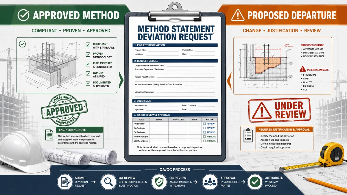
For example: if your specification requires a departure from a referenced standard, that departure must be documented and approved separately — this method statement will not capture that automatically. Always verify against your applicable drawings, specifications, and regulatory requirements.
Method statement content
Scope
Overview
This method statement covers end-to-end activities for the routing, installation, testing, and commissioning of a Pneumatic Tube System (PTS) including:
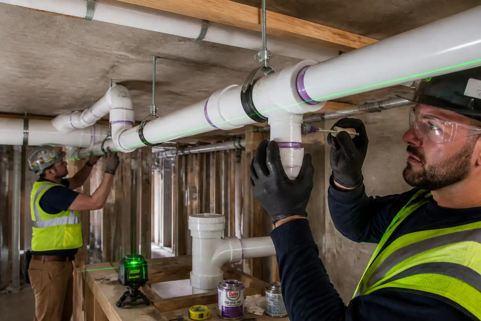
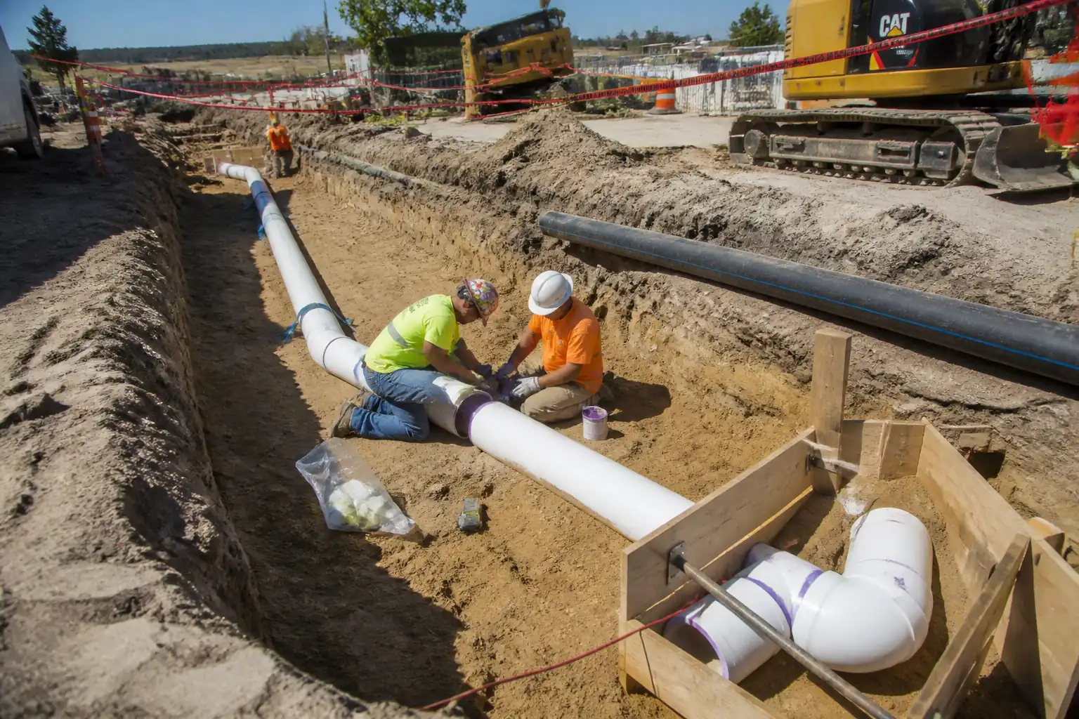
- PVC tube routing and jointing by solvent cementing.
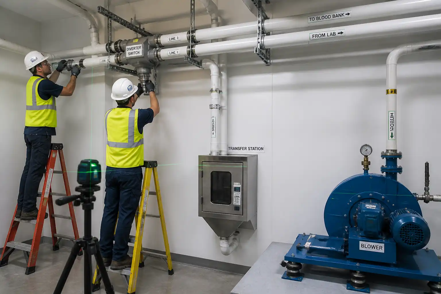
- Installation of diversion branch switches (diverters) and elbows.
- Mounting and alignment of transfer/station terminals (send/receive stations).
- Installation and alignment of system blower(s) with vibration isolation, filtration, and silencers.
- Electrical and controls interconnections, including optical sensor and tracking systems.
- Carrier purge testing, vacuum/pressure integrity testing, airflow verification, and optical sensor tracking verification.
- Handover documentation and as-built records.
Locations
- Above-ceiling voids, risers/shafts, plant room for blower(s), station rooms, and corridors as per approved shop drawings.
Exclusions
- Structural modifications unless specifically shown on approved drawings.
- Permanent power supply installation by others unless stated.
- Firestopping by specialist contractor unless coordinated.
Interfaces
- Architectural ceilings and access panels.
- MEP services (HVAC, electrical trays, sprinklers, medical gases, data) for coordination and clearances.
- BMS/SCADA integration for alarms and monitoring, if required.
Acceptance and Handover
- Demonstrate leak-tightness, route functionality, carrier tracking accuracy, and blower performance per this method and ITP.
- Submit O&M manuals, commissioning reports, and as-built drawings for client approval.
References
| Document Type | Reference / Number | Revision | Notes |
|---|---|---|---|
| Standard | ASTM D1785 / ASTM D2672 | Project specification overrides if stricter. | |
| Standard | ASTM D2855, D2564, F656 | Observe cure times per manufacturer. | |
| Standard | MSS SP-58/69 | Support spacing per manufacturer or SP-69 ranges. | |
| Standard | ACI 318, ICC-ES AC193 / ETA EAD 330087 | Use approved anchors only. | |
| Standard | NFPA 70 / IEC 60364 / IEC 60204-1 | [Verify per local regulations]. | |
| Standard | ISO 5801, ISO 14694, AMCA 204 | For site acceptance checks. | |
| Standard | ISO 10816-3 / 20816-3 | Applies to blower assemblies. | |
| Standard | ANSI/ASME A13.1 (adapted) | Use project legend for routes/stations. | |
| Standard | UL / EN 1366 | Coordinate sleeves and clearances. |
Responsibilities
| Role | Responsibility | Name / Party |
|---|---|---|
| Project Manager | Approve method/ITP, ensure permits and interfaces. | Contractor |
| Engineer | Ensure sequence accuracy and as-built updates. | Contractor |
| QA/QC | Implement ITP, issue NCRs, verify corrective actions. | Contractor |
| HSE | Verify controls, permits, and PPE compliance. | Contractor |
| Supervisor | Test continuity/insulation, labeling. | Contractor |
| Engineer | Execute commissioning plan and performance tests. | Contractor |
| Specialist | Confirm compliance with OEM manuals and warranty. | Vendor |
| Surveyor | Ensure clearances and tolerances per model. | Contractor |
Resources
| Resource Type | Description | Quantity | Remarks |
|---|---|---|---|
| Labor | Cutting, jointing, mounting supports and diverters. | 4–8 [Verify] | |
| Labor | Power/control cabling, terminations, testing. | 2–4 [Verify] | |
| Labor | Blower start-up, airflow and vacuum tests, sensor calibration. | 2–3 [Verify] | |
| Staff | HSE oversight. | 1 | |
| Staff | Hold/witness point control and documentation. | 1–2 [Verify] |
Materials
| Material | Specification / Grade | Quantity | Remarks |
|---|---|---|---|
| PVC-U | DN [Verify] | As per BOQ | |
| PVC-U | As per drawings | ||
| Solvent | As required | ||
| Per drawings | |||
| Per drawings | |||
| As per design | |||
| As required | |||
| As required | |||
| Per route |
Equipment
| Equipment | Capacity / Type | Quantity | Inspection Required |
|---|---|---|---|
| Cold saw | 2 sets | Pre-use check | |
| 1 set | Yes | ||
| As required | Yes | ||
| 1 set | Yes | ||
| As required | Yes | ||
| As required | Yes |
Prerequisites
Approvals and Documentation
- Approved shop drawings, schematics, and routing coordination (BIM/Clash-free) including elevations and support details.
- Approved vendor submittals for tubing, diverters, stations, blowers, and controls.
- ITP and checklists approved by the Engineer/Client.
Site Readiness
- Access clear, ceilings opened, safe working platforms in place.
- Penetrations and sleeves prepared; firestopping strategy coordinated.
- Power availability verified for blower(s) and stations [Verify voltage/phase].
- Spare parts and consumables available (solvent cement/primer within shelf life).
Permits and HSE
- Permit to Work (PTW), Hot Work (if any), Working at Height, and Electrical LOTO permits in place. [Verify per project HSE plan and local regulations].
- Task-Specific Risk Assessment/Method Statement (RAMS) briefed via toolbox talk.
Calibration and Training
- Instruments calibrated with valid certificates.
- Crew trained in solvent cementing per ASTM D2855/OEM; electrical team trained in LOTO; commissioning team trained on OEM software/tools.
Environmental Conditions
- Ambient temperature for solvent cementing: typically 5–38°C; humidity controlled; adequate ventilation. [Verify per manufacturer].
- Ensure dust control for sensitive/clinical areas; schedule noisy works off-hours if required.
Pre-Installation Meeting
- Review sequence, hold/witness points, roles, emergency procedures, and interface points with other trades.
Method Sequence
| Step | Activity | Description | Responsibility | Inspection / Hold Point |
|---|---|---|---|---|
| 1 | Set-out and Verification | Mark centerlines and support points from approved drawings. Confirm clearances to MEP and structure. | Site Engineer | Layout check |
| 2 | Install Supports/Hangers | Fix brackets/Unistrut and hangers at designed spacing with approved anchors. | PTS Technicians | Pull-out/anchor check (sample) |
| 3 | Material Inspection (Pre-Install) | Check pipes/fittings for damage; verify batch numbers, primer/cement expiry; store horizontally supported. | QA/QC | Visual and documents |
| 4 | Cutting and Preparation | Measure, mark insertion depth; cut square; deburr and chamfer 10–15°; dry-fit to confirm alignment. | PTS Technicians | Random dimensional check |
| 5 | Solvent Cement Jointing | Clean, apply primer to pipe and fitting; apply even solvent cement coat; assemble with quarter-turn; hold 30–60 s; wipe excess bead. | PTS Technicians | Witness by QA/QC |
| 6 | Routing and Alignment | Install straight runs without sag; long-radius elbows; maintain minimum bend radii and clearances; install expansion allowances if required. | Site Engineer/Technicians | Visual/level check |
| 7 | Penetrations and Sleeves | Route through walls/slabs via sleeves; install grommets; maintain fire compartmentation. | PTS Technicians | Opening size and finish |
| 8 | Install Diverter Switches | Mount diverters with flanged/coupled connections; align to avoid carrier snagging; connect actuators/sensors. | PTS Technicians/Vendor | OEM alignment check |
| 9 | Install Transfer/Station Terminals | Fix stations to wall/stand; plumb and level; connect tubes and sensors; provide power/data. | PTS Technicians/Electricians | Level and anchor check |
| 10 | Blower Base and Mounting | Position base; install vibration isolators; level; mount blower; fit flexible connectors, filter, silencer. | Technicians | Level, fastener torque |
| 11 | Electrical and Controls Wiring | Install power circuits, control cables, sensor lines; terminate in panels; label all conductors. | Electricians | Continuity/IR test |
| 12 | Cure Time Hold | Allow joints to cure before pressure/vacuum testing and carrier runs. | Site Engineer | Time/temperature log |
| 13 | Pre-Test Internal Clean | Blow out debris with filtered air/vacuum; visual borescope where accessible. | Technicians | Visual |
| 14 | Leak/Integrity Test (Vacuum/Pressure) | Isolate route; apply vacuum (or low positive pressure); monitor decay. | QA/QC with Commissioning | Witness |
| 15 | Airflow and Static Pressure Check | Run blower; measure duct static and velocity at test ports. | Commissioning Engineer | Witness |
| 16 | Blower Vibration/Noise Check | Measure vibration on bearings and base; check noise level at 1 m. | Commissioning Engineer | Witness |
| 17 | Diverter Functional Test | Cycle diverters via HMI/PLC; confirm position feedback and interlocks. | Commissioning/Controls | Witness |
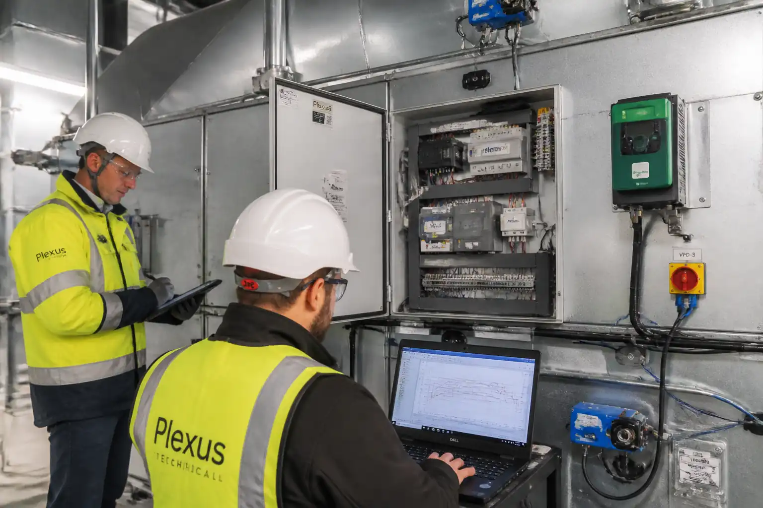
| 18 | Optical Sensor Calibration | Set sensitivity/threshold; align emitters/receivers; verify ID reading/barcode or tag detection. | Controls/Commissioning | Witness |
| 19 | Carrier Purge and Route Proving | Run foam/standard carriers through each route; verify travel times and return paths; observe for snags. | Commissioning/QA | Witness |
| 20 | Integrated System Test (IST) | Operate multiple routes simultaneously; verify controls logic, alarms, and tracking across stations and diverters. | Commissioning Team | Witness by Engineer |
| 21 | Labeling and As-Builts | Apply permanent labels to routes, components, and panels; update as-built drawings and O&M. | Site Engineer/QA | Visual |
Health, Safety, and Environment (HSE) – Task-Specific Safety Controls
Principal Hazards and Controls
- Hazard: Working at height (ceilings/risers).
- Consequence: Falls causing serious injury or fatality.
- Engineering/Procedural Control: Use MEWP or mobile scaffold with guardrails and toe boards; maintain 3:1 ladder rule for short-duration tasks only; install fall arrest where required; maintain exclusion zone below.
- Required PPE: Full-body harness (if fall arrest), hard hat, non-slip safety boots, gloves, eye protection.
- Collective Preventive Measure: Properly erected and inspected access platforms; barricades and signage.
-
Inspection/Permit/Supervision: Weekly scaffold/MEWP inspection tag; PTW for MEWP; competent operator supervision. [Verify per project HSE plan and local regulations]
-
Hazard: Solvent cement/primer vapors (flammable, irritant).
- Consequence: Fire, respiratory/skin/eye irritation, CNS effects.
- Engineering/Procedural Control: Use in well-ventilated areas; no ignition sources; use closed containers; limit quantities; provide spill kits and fire extinguishers (Class B); follow SDS.
- Required PPE: Chemical-resistant gloves (nitrile), goggles/face shield, long sleeves; respirator with organic vapor cartridges if ventilation inadequate.
- Collective Preventive Measure: Local exhaust ventilation; flammable cabinet storage; no-smoking policy.
-
Inspection/Permit/Supervision: SDS review; Hot Work assessment; HSE inspections; container expiry checks.
-
Hazard: Power tools and cutting operations.
- Consequence: Lacerations, eye injury, amputation.
- Engineering/Procedural Control: Use cold-cut tools for plastics; guards in place; two-hand operation; secure workpiece; keep hands clear; lockout tools when changing blades.
- Required PPE: Cut-resistant gloves, safety glasses/face shield, hearing protection where needed.
- Collective Preventive Measure: Task zoning, cable management, RCD-protected circuits.
-
Inspection/Permit/Supervision: Pre-use tool inspection; PAT testing tags valid.
-
Hazard: Overhead lifting and manual handling of long tubes.
- Consequence: Strains, crush injuries, dropped objects.
- Engineering/Procedural Control: Team lifts for >20 kg or >3 m lengths; use trolleys/slings; secure loads; never work under suspended loads.
- Required PPE: Safety boots with toe protection, gloves, hard hat.
- Collective Preventive Measure: Exclusion zones; tag lines; route planning.
-
Inspection/Permit/Supervision: Lifting gear certifications; lifting plan if using hoists.
-
Hazard: Electrical works and energization.
- Consequence: Electric shock, burns, arc flash.
- Engineering/Procedural Control: LOTO procedures; verify absence of voltage; insulating mats; rated tools; cover exposed live parts.
- Required PPE: Electrical gloves, arc-rated clothing (as required), eye/face protection.
- Collective Preventive Measure: Barriers and lockable panels; RCDs.
-
Inspection/Permit/Supervision: Electrical PTW; competent supervisor; test records.
-
Hazard: Confined/poorly ventilated shafts.
- Consequence: Asphyxiation, exposure to vapors, entrapment.
- Engineering/Procedural Control: Atmosphere test; forced ventilation; standby watch; rescue plan.
- Required PPE: Gas detector, harness where required, two-way radio.
- Collective Preventive Measure: Permit-controlled access, signage.
-
Inspection/Permit/Supervision: Confined Space PTW; entry log; attendant present.
-
Hazard: Noise and vibration from blower start-up.
- Consequence: Hearing damage, nuisance.
- Engineering/Procedural Control: Fit silencers; schedule testing; limit exposure duration.
- Required PPE: Hearing protection (SNR [Verify]).
- Collective Preventive Measure: Acoustic enclosures where specified.
-
Inspection/Permit/Supervision: Noise survey during commissioning.
-
Hazard: Sharp edges/burrs inside tubes.
- Consequence: Hand cuts, carrier damage leading to blockage.
- Engineering/Procedural Control: Mandatory deburring; inspection mirror/borescope checks.
- Required PPE: Cut-resistant gloves, sleeves.
- Collective Preventive Measure: Bench jigs and deburring tools.
-
Inspection/Permit/Supervision: Random QA checks per joint.
-
Hazard: Firestopping interfaces.
- Consequence: Compromised fire integrity.
- Engineering/Procedural Control: Use approved systems; coordinate with specialist; maintain annular gaps per listing.
- Required PPE: Standard site PPE.
- Collective Preventive Measure: Fire watch if hot works nearby.
-
Inspection/Permit/Supervision: Firestopping inspection records and approvals.
-
Hazard: Working near existing live services.
- Consequence: Utility strike, service outage.
- Engineering/Procedural Control: Service detection and permits; use non-invasive fixings where required; stop work on unexpected discovery.
- Required PPE: Standard site PPE.
- Collective Preventive Measure: Coordination drawings and permits-to-drill.
- Inspection/Permit/Supervision: Permit and sign-off from building management.
Environmental Controls
Controls for Environmental Impact
- Solvent VOC Management
-
Use low-VOC products where approved; maintain tight lids; decant minimal quantities; provide local ventilation and carbon filters if needed. Collect solvent/primer waste in labeled containers for hazardous disposal. [Verify per project environmental plan]
-
Noise and Vibration
-
Limit blower testing to agreed hours; use silencers and isolation mounts; perform baseline and post-test noise surveys if required.
-
Dust and Debris
-
Use cold-cut methods and on-tool extraction; vacuum internal tubes before tests; maintain clean work areas; prevent debris entering occupied spaces.
-
Waste Segregation and Recycling
-
Segregate PVC offcuts for recycling where facilities exist; recycle cardboard/plastic packaging; dispose of mixed waste per local regulation.
-
Energy and Commissioning Efficiency
-
Optimize blower settings (VFD) to reach design with minimal power; shut down equipment when idle during commissioning.
-
Spill Prevention
-
Store solvents on spill trays; have spill kits on hand; clean spills immediately; prevent entry to drains.
-
Protected/Clinical Areas
- Where works occur in clinical/clean areas, use HEPA vacuums, tack mats, and infection control barriers; maintain negative/positive pressure per hospital policy where applicable. [Verify per project protocols]
Quality Assurance / Quality Control
QA/QC Strategy
- Hold/Witness Points
- Cure time before testing (Hold).
- Leak/integrity test (Hold).
- Optical sensor calibration (Hold).
- Route proving (Hold).
-
Integrated System Test (Witness).
-
Tolerances and Workmanship
- Alignment: ±5 mm over 10 m; sag ≤5 mm between supports.
- Joint quality: continuous external bead; insertion to mark; internal step ≤0.5 mm.
-
Station level: ±2 mm/m; blower base: ±1 mm/m.
-
Testing Frequencies
- Leak test: each discrete route/section.
- Airflow/static pressure: each blower/zone.
- Sensor tracking: each station and diverter path; minimum 50 passes.
-
Electrical testing: each circuit; 100% continuity and IR.
-
Documentation
-
Maintain joint logs, MIRs, support checklists, electrical test sheets, calibration certs, commissioning reports, and as-builts.
-
Nonconformance and Corrective Action
-
Record NCRs for failed leak tests, misalignment, sensor faults. Investigate cause; repair/retest until acceptance.
-
Training and Competency
-
Only trained personnel perform solvent cementing and commissioning. Keep training records onsite.
-
Traceability
- Batch numbers for cement/primer and pipe heat numbers recorded against joint log for critical routes [Verify if required by contract].
Attachments
- Sample checklists: Material Inspection Report (MIR), Support Installation Checklist, Joint Log (with batch numbers), Electrical Test Sheet.
- Commissioning forms: Leak Test Report, Airflow/Static Pressure Report, Vibration/Noise Report, Diverter Functional Test, Sensor Calibration Record, Route Proving Report, IST Report.
- Vendor manuals: Diverter assemblies, Stations, Blower(s), Sensors.
- Approved shop drawings and schematics with revision status.
- Risk Assessment and Toolbox Talk records.
- Calibration certificates for all instruments used.
- As-built drawings and labeling legend.
This content is a read-only public reference. Download or customize to get an editable version.
ITP preview
The first inspection activities from the linked ITP for Method Statement: Pneumatic Tube System (PTS) Routing and Installation:
| Activity | Inspection / Test | Acceptance Criteria | Responsibility | Record |
|---|---|---|---|---|
| Material receipt and verification | Check certificates, sizes, grades, expiry (cement/primer), visual condition. | Compliant with approved submittals and ASTM refs; no damage; valid shelf life. | QA/QC | MIR, COC/MTC copies |
| Supports and anchors installation | Check spacing, type, torque, embedment (sample). | MSS SP-58/69; torque per data; embedment per anchor approval. | QA/QC / Engineer | Support inspection sheet |
| PVC cutting and joint preparation | Verify squareness, chamfer, deburring, dry-fit. | End squareness ≤1 mm; clean/dry surfaces; insertion depth marked. | QA/QC | Fit-up record |
Showing 3 of 15 inspection activities. View full ITP →
Related Inspection and Test Plan
An Inspection and Test Plan (ITP) is available for Method Statement: Pneumatic Tube System (PTS) Routing and Installation. The ITP defines the inspection activities, acceptance criteria, hold and witness points, responsible parties, and records required to verify the work described in this method statement.
View the Method Statement: Pneumatic Tube System (PTS) Routing and Installation ITP →Frequently asked questions
Continue with related Quollnet resources connected to this method statement.