
Inspection and Test Plan for Method Statement: Pneumatic Tube System (PTS) Routing and Installation
AI-assisted inspection and test plan connected to a method statement, with PDF and Excel export.
More than a static template
Unlike a downloadable Word or PDF template, this ITP is an AI-assisted editable starting point directly connected to its method statement. Every inspection activity, hold point, and acceptance criterion is structured and ready to adapt to your project.
- AI-assisted customization — Tailor inspection activities and acceptance criteria to your specific project scope.
- Linked method statement — This ITP is connected to the corresponding method statement describing the work sequence.
- Multiple export formats — Download as a formatted PDF or editable Excel spreadsheet.
- Editable starting point, not a final document — Review and verify all content against your project specifications and standards before use.
What you can customize
When you save this ITP to your account, every inspection row becomes editable. You can add, remove, or modify:
- Inspection activity — Description of what is being inspected.
- Inspection type — Hold point (H), Witness point (W), Review (R), or Monitor (M).
- Responsibility — Contractor, subcontractor, engineer, or client.
- Frequency — How often the inspection occurs.
- Acceptance criteria — Referenced standard or specification requirement.
- Records — Forms, test reports, or checklists required as evidence.
Why this ITP is used
To verify that PTS installation complies with standards, OEM requirements, and contract performance criteria before handover.
Who uses this inspection and test plan
QA/QC engineers, site engineers, commissioning teams, vendor specialists, and the Engineer/Client representatives.
When this ITP is prepared and submitted
From material receipt through installation to final integrated system testing and handover.
Who receives or approves this ITP
Engineer/Client for review, comment, and approval prior to works.
Inspection scope
Materials verification, support installation, joint quality, alignment, electrical tests, leak/airflow checks, vibration/noise, sensor calibration, route proving, and IST.
Typical hold, witness, and review points
Hold: cure time, leak test, sensor calibration, route proving. Witness: integrated system test, blower vibration/noise.
Typical inspection records
MIRs, joint logs, support checklists, electrical test sheets, leak and airflow reports, vibration/noise reports, sensor calibration records, route proving and IST reports, as-builts.
Important approval note
This ITP is an AI-assisted editable starting point, not a pre-approved document. Before use on any project, all inspection activities, hold points, and acceptance criteria must be reviewed and approved by the relevant parties (superintendent, principal contractor, or client representative) in accordance with your contract and project quality plan.
Always verify acceptance criteria against your applicable drawings, specifications, and regulatory requirements. Hold points must be confirmed with the relevant authority before work proceeds past that point.
Inspection and test plan
| Activity | Inspection / Test | Acceptance Criteria | Responsibility | Record |
|---|---|---|---|---|
| Material receipt and verification | Check certificates, sizes, grades, expiry (cement/primer), visual condition. | Compliant with approved submittals and ASTM refs; no damage; valid shelf life. | QA/QC | MIR, COC/MTC copies |
| Supports and anchors installation | Check spacing, type, torque, embedment (sample). | MSS SP-58/69; torque per data; embedment per anchor approval. | QA/QC / Engineer | Support inspection sheet |
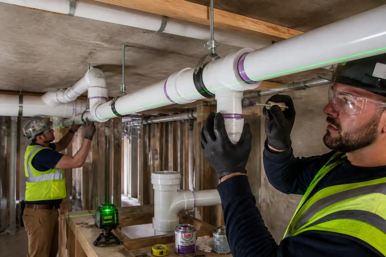
| PVC cutting and joint preparation | Verify squareness, chamfer, deburring, dry-fit. | End squareness ≤1 mm; clean/dry surfaces; insertion depth marked. | QA/QC | Fit-up record |
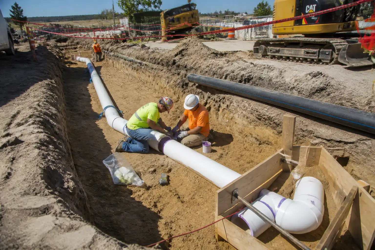
| Solvent-cemented joints | Witness primer/cement application; check bead and insertion. | ASTM D2855 compliant; continuous bead; full insertion to mark; cure per OEM. | QA/QC (Witness) | Joint log with batch numbers |
| Routing and alignment | Level/sag checks; internal step via feel/borescope at samples. | Sag ≤5 mm between supports; internal step ≤0.5 mm; clearances maintained. | Engineer/QA | Routing checklist |
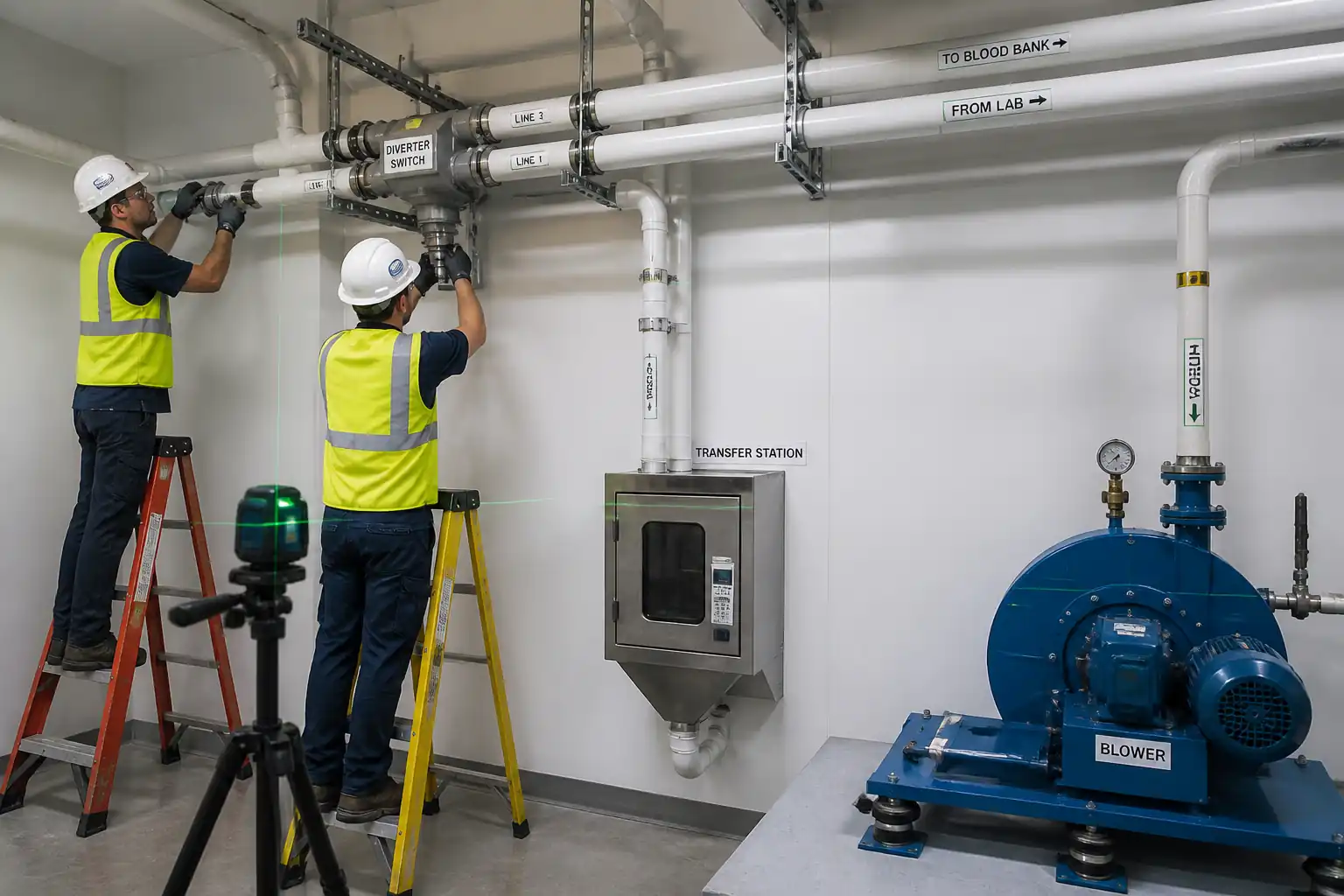
| Diverter installation | Alignment and functional dry run; feedback IO check. | Smooth actuation; feedback correct; no internal snag points. | QA/QC + Vendor | Diverter checklist |
| Station mounting | Level, plumb, anchor torque, door function. | ±2 mm/m; torque per data; smooth operation. | QA/QC | Station inspection sheet |
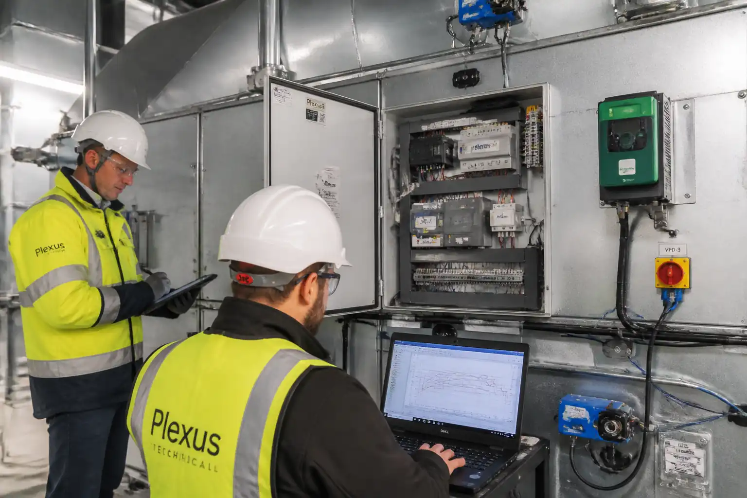
| Electrical tests | Continuity, insulation resistance, polarity, grounding. | IR ≥1 MΩ @ 500 VDC [Verify]; correct polarity/labels; continuity <1 Ω (typical) [Verify]. | Electrical Supervisor/QA | Electrical test report |
| Leak/Integrity test | Vacuum/pressure decay test per sectioned route. | ±2.5–3.7 kPa hold for 10 min; decay ≤0.12 kPa (0.5 in.wg); no soap film growth at joints. | QA/QC (Hold) | Leak test report |
| Airflow/static pressure verification | Measure airflow and static pressure with calibrated instruments. | Flow within −5%/+0% of design; static pressure within ±10%. | Commissioning | Airflow report |
| Blower vibration/noise | Measure vibration velocity RMS and noise at 1 m. | ≤4.5 mm/s RMS (ISO 10816-3) [Verify class]; noise within project limits [Verify]. | Commissioning/QA | Vibration/noise report |
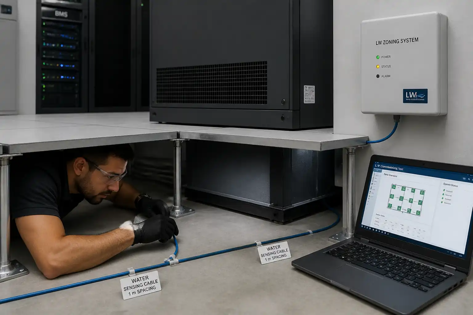
| Optical sensor calibration and tracking | Calibrate sensors; run 50-pass detection test; verify timestamps. | 100% detection; 0 misreads; timestamp skew ≤0.2 s. | Controls/Commissioning (Hold) | Calibration and tracking report |
| Carrier purge and route proving | Run foam/standard carriers on each route (10 cycles). | 10/10 successful per route; travel time within ±10% of baseline; no abnormal marks. | Commissioning (Hold) | Route proving report |
| Integrated System Test (IST) | Simultaneous multi-route operation; fault injection; recovery. | No carrier loss; correct alarms/interlocks; throughput per design. | Commissioning/Engineer (Witness) | IST report |
| Final documentation and as-builts | Review completeness of records and drawings. | Full package submitted and approved. | QA/QC | Handover dossier |
This table is a read-only public reference. Download the PDF or Excel version, or customize this ITP to edit it for your project.
Frequently asked questions
Related method statement
This Inspection and Test Plan is associated with the Method Statement: Pneumatic Tube System (PTS) Routing and Installation method statement, which describes the step-by-step construction sequence, resources, materials, equipment, safety controls, and environmental controls for this activity.
View the Method Statement: Pneumatic Tube System (PTS) Routing and Installation method statement →Continue with related inspection, method statement, article, and checklist resources.