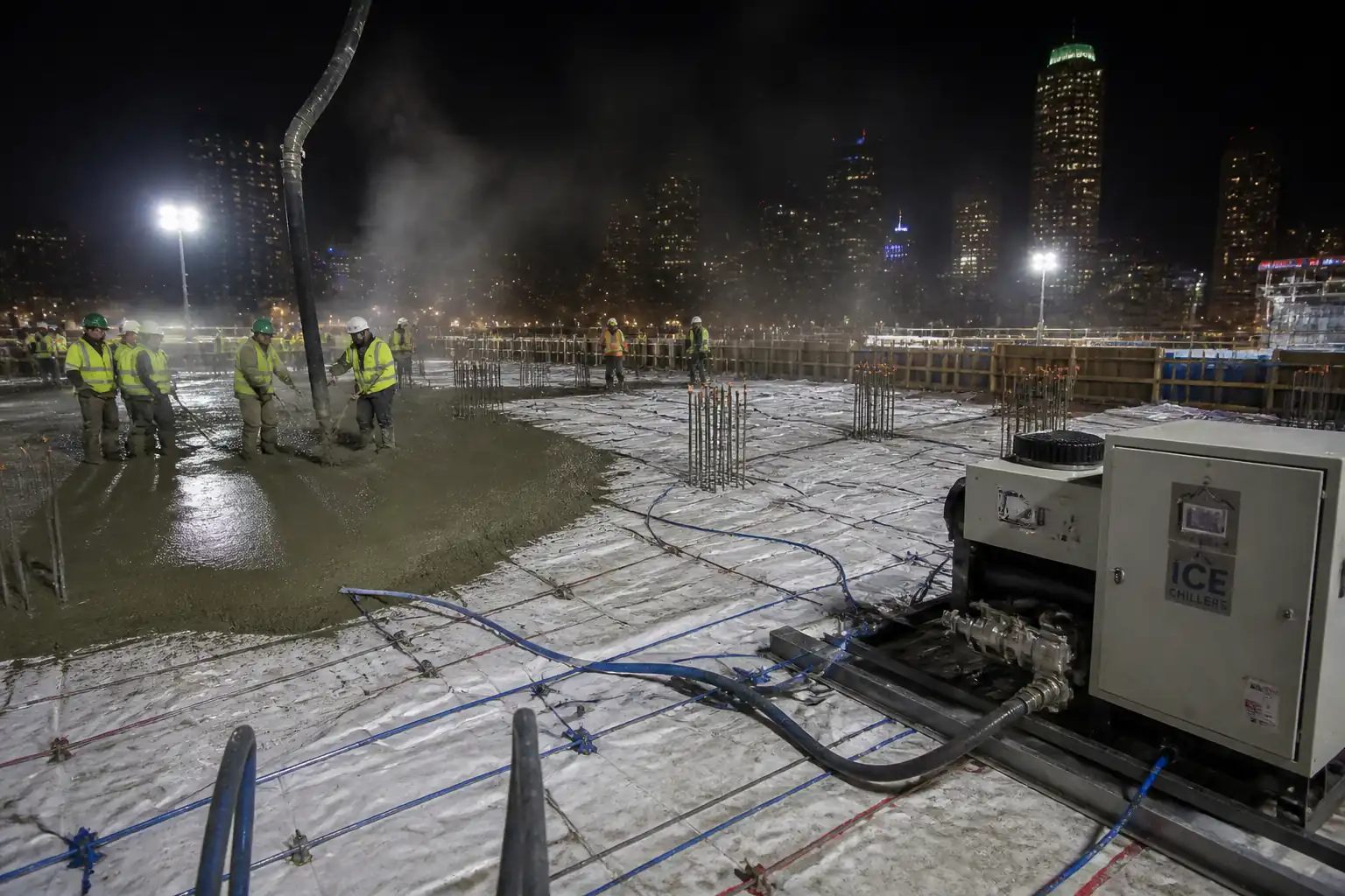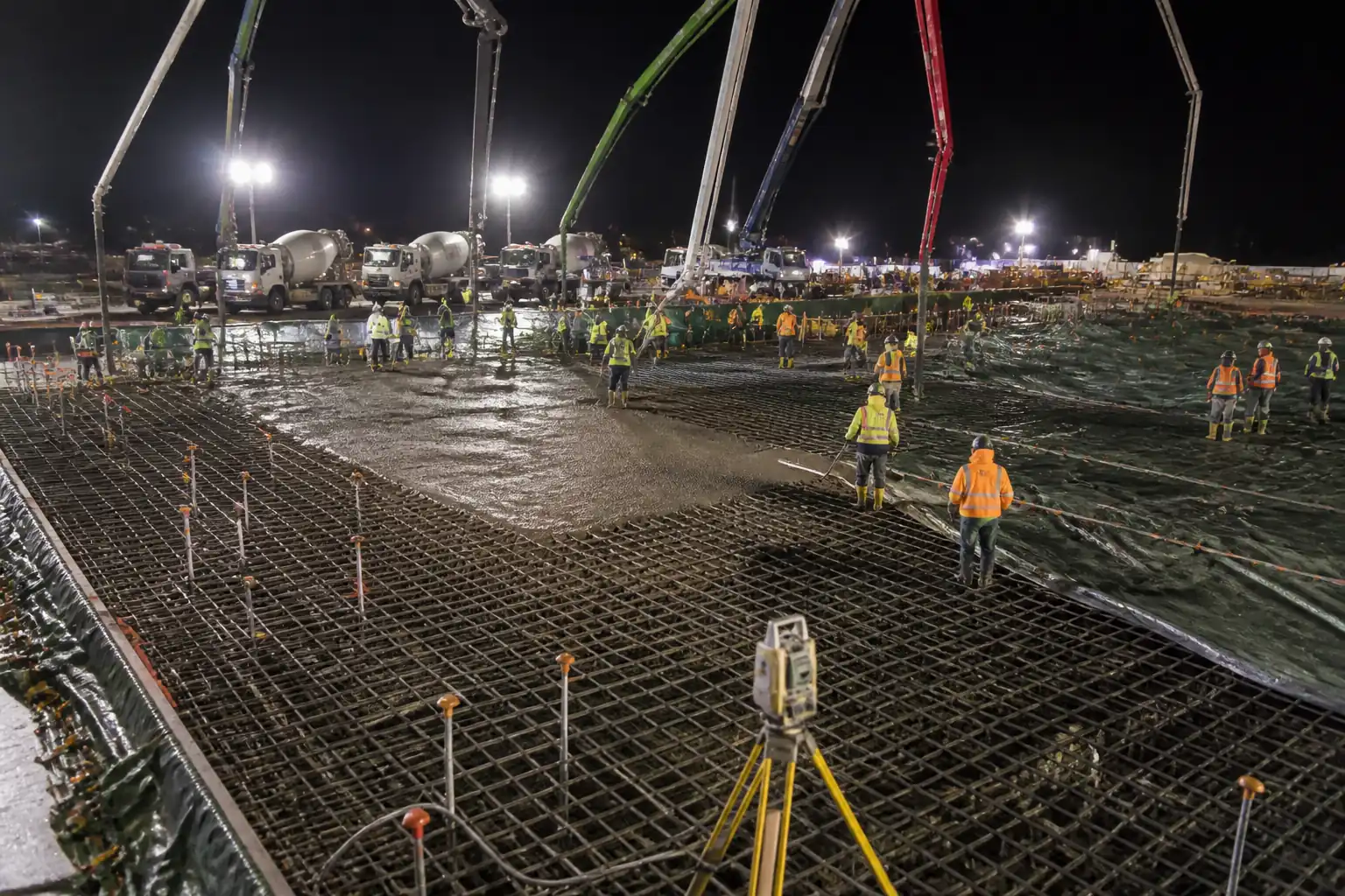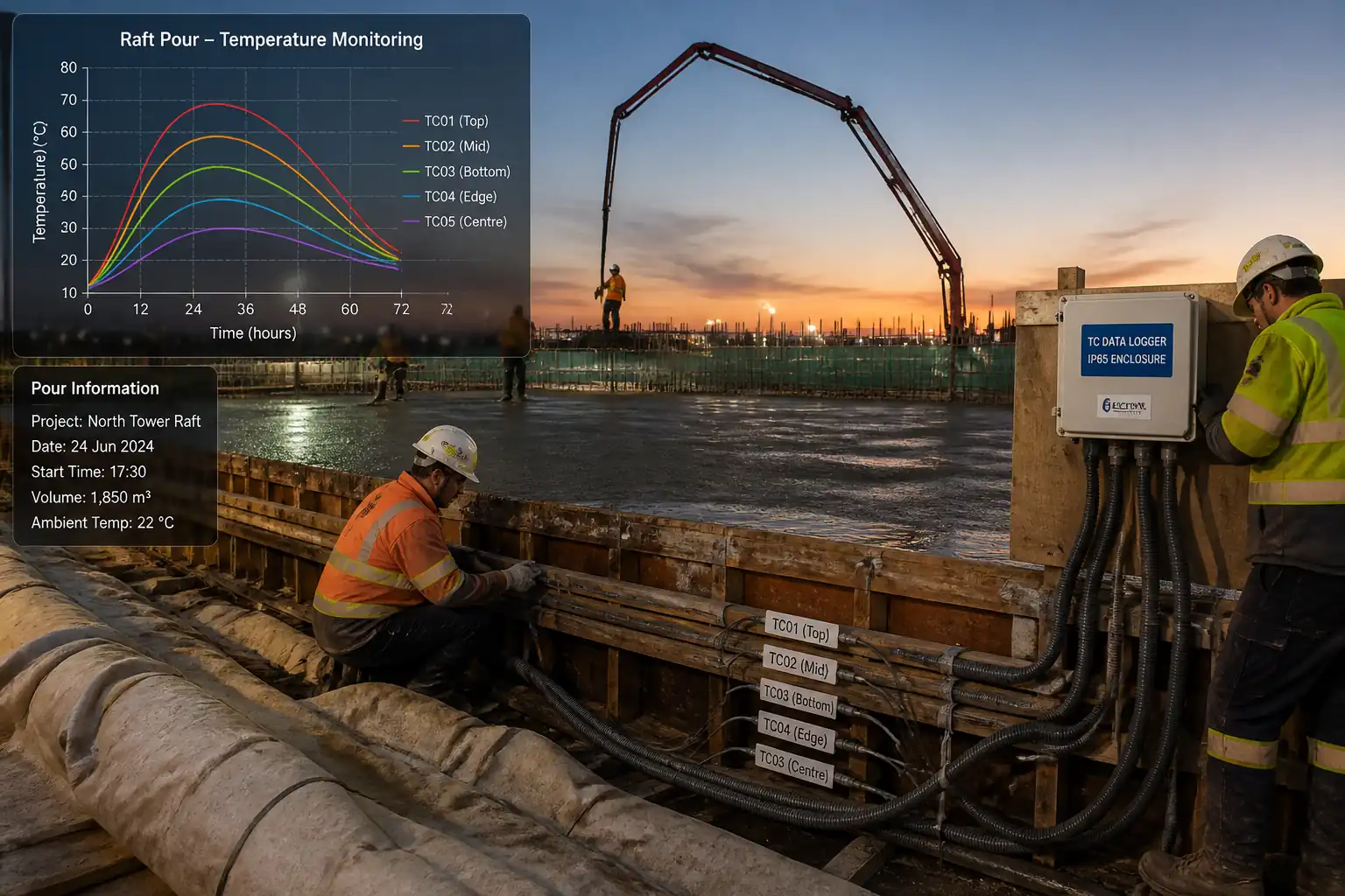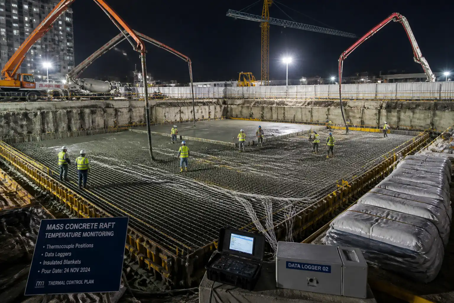

Method Statement: Mass Concrete Cooling Pipe System Installation and Operation – Method Statement
AI-assisted method statement with matching ITP, PDF download, and Excel export.
More than a static template
Unlike a downloadable Word or PDF template, this method statement is an AI-assisted editable starting point connected directly to a matching Inspection and Test Plan. Every section is structured, project-adaptable, and ready to export.
- AI-assisted drafting — Customize every section with AI for your specific project scope.
- Linked ITP — A matching inspection and test plan is generated alongside the method statement.
- Multiple export formats — Download as a formatted PDF or editable Excel spreadsheet.
- Editable starting point, not a final document — Review, verify, and adjust all content against your project requirements before use.
Static template vs. Quollnet workflow
| Feature | Static template | Quollnet |
|---|---|---|
| Project-specific content | Manual fill-in required | AI-assisted customization |
| Linked ITP | Separate document, no link | Matching ITP included |
| Export formats | Usually PDF only | PDF and Excel |
| Structured sections | Free-form layout | 13 standardized sections |
| Saved to your account | Local file only | Cloud-saved, reusable |
| Content accuracy | You verify everything | AI-assisted, you still verify |
| Cost | Often free but time-intensive | Free to customize and download |
What you can customize
When you save this method statement to your account, every section becomes editable. The following 13 sections are included:
- Scope — Defines the activity and its boundaries.
- References — Standards, specifications, and drawings.
- Responsibilities — Roles and accountabilities.
- Resources — Labour, plant, and equipment summary.
- Materials — Materials and compliance requirements.
- Equipment — Tools and equipment details.
- Prerequisites — Hold points and pre-conditions.
- Method sequence — Step-by-step construction sequence.
- Safety controls — HSE risk controls and PPE.
- Environmental controls — Environmental mitigation measures.
- QA/QC — Quality inspection and test requirements.
- ITP — Inspection and Test Plan table (has its own page).
- Attachments — Referenced drawings and documentation.
Why this method statement is used
This method statement is used to define and communicate the approved procedure for carrying out method statement: mass concrete cooling pipe system installation and operation on site. It ensures the work is planned in advance, the correct resources and controls are in place, and all personnel understand responsibilities, sequence, quality requirements, and safety controls before work begins. It aligns site execution with the documented scope and acceptance expectations.
Who uses this method statement
This method statement is used by contractors, site supervisors, project engineers, QA/QC engineers, HSE officers, consultants, and client representatives. It serves as a shared reference for planning, execution, supervision, inspection, and approval of the activity on site.
When it is prepared and submitted
The method statement is prepared before the work activity starts and submitted as part of the pre-construction documentation package for review and approval.
Who reviews or approves it
The method statement is usually submitted to the client representative, consultant, resident engineer, or project management consultant for review and approval before the work commences.
Important approval note
This method statement is an AI-assisted editable starting point, not a pre-approved document. Before use on any project, all content must be reviewed and approved by the relevant parties (superintendent, principal contractor, or client representative) in accordance with your contract and project quality plan.
For example: if your specification requires a departure from a referenced standard, that departure must be documented and approved separately — this method statement will not capture that automatically. Always verify against your applicable drawings, specifications, and regulatory requirements.
Method statement content
Scope
Overview
This method statement covers the end-to-end works for mass concrete thermal control using embedded cooling pipe circuits, including:
- Pre-installation engineering checks (thermal analysis review, shop drawings, ITP, WMS).
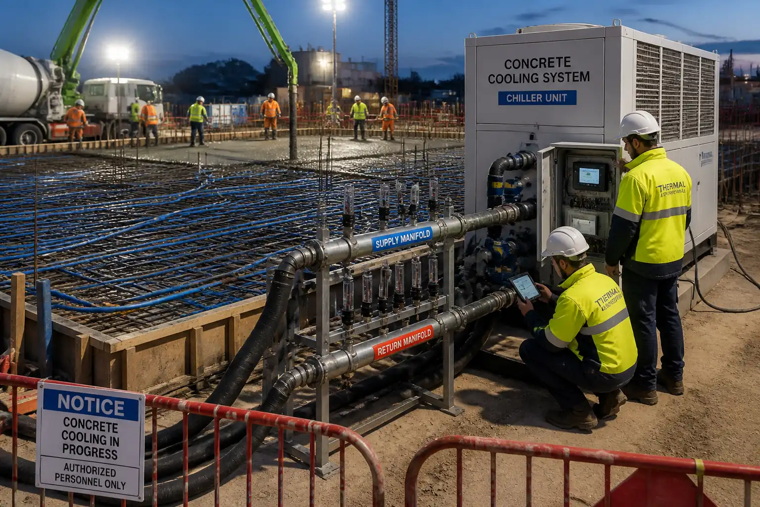
- Supply, inspection, and installation of embedded cooling pipes, manifolds, headers, valves, flow meters, thermocouples, and data acquisition.
- Pipe layout verification, pressure/leak testing, flushing, and isolation.
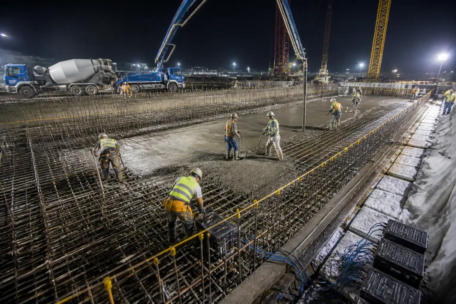
- Sequenced coordination with reinforcement, formwork, and concrete placement.
- Cooling water circulation start-up, balancing, monitoring, and controlled ramp-down.
- Temperature measurement, data logging, acceptance verification against design thermal thresholds.
- Reporting, as-built records, and demobilization/pipe closeout.
Limits and Interfaces
- Applicable to all mass concrete pours where predicted maximum temperature rise or core-to-surface differential requires active cooling.
- Interfaces with concrete placement, curing, reinforcement, electrical/SCADA (for data logging), and HSE permitting.
Key Objectives
- Limit maximum concrete core temperature [Typical: ≤ 65–70°C, Verify per project specifications].
- Limit core-to-surface differential temperature [Typical: ≤ 11°C (20°F) per ACI 207, Verify per project specifications].
- Limit rate of temperature change [Typical: ≤ 1°C/hour and ≤ 10°C/24h, Verify per project specifications].
- Ensure leak-free, properly supported circuits with sufficient cover and non-interference with reinforcement and embedded items.
References
| Document Type | Reference / Number | Revision | Notes |
|---|---|---|---|
| Standard | ACI 207.1R / 207.2R | ||
| Standard | ACI 301 / ACI 318 | ||
| Standard | ACI 305R / ACI 306R | Where applicable [Verify per project specifications]. | |
| Standard | ASTM C1064/C1064M | ||
| Standard | ASTM C1074 | ||
| Standard | BS EN 206 / BS 8500 | Use if project in EU/UK jurisdiction. | |
| Standard | ASTM F2164 | If HDPE is used. | |
| Standard | ISO 4427 / ASTM D3035 | For PE100 SDR-rated pipes. | |
| Standard | ASTM A53 / A106 | If steel pipe option is selected. | |
| Standard | ASTM E230/E230M | ||
| Standard | ISO 9001, ISO 14001, ISO 45001 | [Verify per project HSE plan and local regulations]. |
Responsibilities
| Role | Responsibility | Name / Party |
|---|---|---|
| PM | PM | Contractor |
| CM | CM | Contractor |
| Engineer | SE | Contractor |
| QA/QC | QA/QC | Contractor |
| HSE | HSE | Contractor |
| Supervisor | MEP Supv | Contractor |
| Supervisor | Rebar Supv | Contractor |
| Surveyor | Survey | Contractor |
| Third Party | ITA | Independent |
| Client Rep | ER | Engineer |
Resources
| Resource Type | Description | Quantity | Remarks |
|---|---|---|---|
| Labor | Install and secure embedded pipes and manifolds. | 1 crew/shift | |
| Labor | Operate chiller/pumps, flow balance, instrumentation setup. | 1 team | |
| Labor | Inspections, verification, as-builts. | As required |
Materials
| Material | Specification / Grade | Quantity | Remarks |
|---|---|---|---|
| HDPE/CS | SDR and grade per design [Verify] | As per drawings | |
| HDPE/CS | PN16 or per design [Verify] | ||
| HDPE/Brass/SS | Compatible with pipe | ||
| Thermocouples | Lengths per pour | ||
| Plastic/nylon | |||
| Armaflex or equal | |||
| HDPE/CS caps, grout |
Equipment
| Equipment | Capacity / Type | Quantity | Inspection Required |
|---|---|---|---|
| Chiller | As calculated [kW/RT] | 1 set | |
| Centrifugal | Flow/head per calc | 2 (D/S) | |
| Meters & gauges | As per circuits | ||
| Logger | 1 system | ||
| Hydro pump | Up to 10 bar [Verify] | 1 | |
| Generator/UPS | As required |
Prerequisites
- Approved shop drawings for pipe routing, manifolds, thermocouple locations, penetrations, and supports.
- Approved Method Statement and ITP, with risk assessment and permits [Verify per project HSE plan and local regulations].
- Thermal analysis/model indicating expected heat of hydration, target peak temperature, differential limits, and cooling capacity calculations.
- Mix design and batching temperature control submittals (e.g., SCMs, aggregate pre-cooling, ice/chilled water use) aligned with ACI 207/ACI 305R.
- Calibrated data loggers and thermocouples with certificates valid within 12 months.
- Materials delivered, inspected, and stored to prevent UV/physical damage.
- Confirmation of rebar shop drawings coordination: pipe clearances, cover, and fixing method.
- Access, lifting plans, and work platforms established; exclusion zones marked.
- Chiller/pump skid located on stable pad; drainage for condensate and test water provided.
- Emergency response and contingency plan for power loss, leaks, or temperature excursions.
- Pre-activity meeting with concrete, rebar, MEP, QC, and HSE teams to confirm sequence and hold points.
Method Sequence
| Step | Activity | Description | Responsibility | Inspection / Hold Point |
|---|---|---|---|---|
| 1 | Engineering verification | Review thermal model, confirm target limits: peak core temp [≤65–70°C, Verify], max ΔT core–surface [≤11°C, Verify], max cooling rate [≤1°C/h, Verify]. Validate required total pipe length, circuit spacing, and chiller/pump capacity. | Engineering | Document review |
| 2 | Survey and set-out | Mark manifold locations, pipe corridors, penetrations. Tolerance ±10 mm. Avoid clashes with anchors, embedded items. | Surveyor | Check marks |
| 3 | Pipe prefabrication | Cut/prepare pipe coils/circuits to shop drawing lengths; fit identification tags (circuit ID, length, zone). Maintain bend radius ≥10×OD (HDPE). Deburr steel pipe ends if used. | MEP Workshop | Visual |
| 4 | Dry layout and clearance check | Lay pipes atop lower mat reinforcement per drawings. Maintain clearance to rebar: ≥25 mm from bars and ≥150 mm from concrete surface [Verify]. Support spacing 0.8–1.2 m to prevent float/movement. Avoid interference with vibrators and pour sequence. | Site Engineer | Dimensional check |
| 5 | Fixing and tying | Secure pipes to reinforcement with non-abrasive ties. Protect at rebar chair contact points. Provide expansion loops at corners. Ensure penetrations are sleeved and sealed to prevent grout ingress. | Pipe Crew | Visual |
| 6 | Manifold installation | Install supply/return manifolds with isolation valves, drains, vents, and flow measurement points. Insulate exposed sections. Provide supports to prevent settlement or vibration. | MEP Team | Alignment |
| 7 | Pressure/leak testing | Hydrotest each circuit/manifold before concrete. Test pressure: 1.5×design operating pressure, not less than 6 bar unless otherwise designed [Verify]. Hold 2 h; acceptable pressure drop ≤5% with no visible leaks (ASTM F2164 guidance for PE). Record ambient temperature and compensate if needed. | QA/QC | Witness (Hold Point) |
| 8 | Flushing and pre-charge | Flush debris with clean water through strainers. Leave circuits positively pressurized (e.g., 1–2 bar air-free water) to maintain shape during pour. Close valves and cap. | MEP Team | Visual/flow check |
| 9 | Thermocouple installation | Install sensors at core, mid-depth, and near-surface (≥50–75 mm from surface) per thermal plan. Secure leads away from vibrators. Label channels and protect exit points. | QA/QC | Function test |
| 10 | Pre-pour inspection | Joint inspection with Engineer: verify pipe IDs, routing, supports, pressure status, sensor locations, manifold readiness, data logger setup, and access. Close Hold Point. | QA/QC & Engineer | Hold Point |
| 11 | Concrete placement coordination | During pour, protect pipework and sensors from damage. Avoid direct vibrator contact. Maintain curing regime (e.g., wet coverings/insulation) to minimize surface cooling shock. | Construction | Surveillance |
| 12 | Start cooling circulation | Initiate circulation per thermal plan after initial set or as soon as safe connections are available (typically 4–12 h after pour [Verify]). Start with tempered water (e.g., 15–20°C) to avoid thermal shock, then reduce supply temperature in stages toward design (e.g., 4–10°C). | MEP Team | Start-up checklist |
| 13 | Flow balancing and control | Adjust circuit valves to achieve target return ∆T (e.g., 5–10°C) and designed flow per circuit. Record flow and supply/return temps. Prioritize hotter zones. | MEP/SE | Meter readings |
| 14 | Monitoring and adjustments | Log core, mid, surface temps at ≤10 min intervals initially, then ≤30 min after stabilization. Maintain limits: peak, ΔT core-surface, and cooling rate. Adjust flows/supply temp to keep within limits. | QA/QC | Continuous |
| 15 | Contingency actions | If ΔT exceeds limit or rising rapidly: increase flow, raise surface insulation/curing, reduce cooling ramp rate, deploy supplemental surface blankets, or temporarily increase supply temp to slow gradient. Notify Engineer. | PM/QA/QC | Event log |
| 16 | Ramp-down and termination | When temperatures stabilize and ΔT consistently within limit for ≥24–48 h [Verify], increase supply temp gradually, then stop circulation. Avoid cooling cessation causing >1°C/h rise. Isolate, drain and cap circuits. | MEP/QA/QC | Shutdown check |
| 17 | Post-operation disposition | Leave embedded pipes capped and dry; or fill with approved non-shrink grout if specified [Verify]. Remove temporary manifolds/hoses and restore penetrations. Update as-builts. | Site Engineer | Final visual |
| 18 | Thermal performance report | Compile plots of temperature vs time, peak temps, ΔT, cooling hours, flow/energy summary, excursions and corrective actions, and compliance statement vs criteria. | QA/QC | Engineer review |
Health, Safety, and Environment — Safety Controls
Task-specific hazards and controls
1) Hazard: Pressurized hydrotest and operating circuits
- Consequence: Hose/pipe burst causing impact injuries and water jets
- Engineering/procedural control: Use rated hoses/fittings; barricade test area; test with water (no air); increase pressure gradually; monitor with calibrated gauge; relieve pressure before disconnection
- Required PPE: Safety goggles/face shield, gloves, safety boots
- Collective preventive measure: Physical barriers/exclusion zone; pressure relief valve at manifold
- Inspection/permit/supervision: Hydrotest checklist; supervisor present; gauge calibration verified; PTW if near public areas [Verify per project HSE plan and local regulations]
2) Hazard: Chiller/pump electrical and rotating machinery
- Consequence: Electric shock, entanglement
- Engineering/procedural control: RCD/GFCI protection; lockable isolators; guards on rotating parts; cable management; competent operators only
- PPE: Dielectric gloves for electricians, standard PPE for operators
- Collective measures: Dedicated plant room or fenced skid; spill mats for oil
- Inspection/permits: Pre-start inspection; Electrical PTW/LOTO; maintenance records
3) Hazard: Slips, trips, and falls over pipework and hoses
- Consequence: Sprains/fractures
- Engineering/procedural control: Routed walkways and hose bridges; tidy routing; high-visibility markings; night lighting
- PPE: Safety boots with slip-resistant soles
- Collective measures: Segregated walkways; housekeeping plan
- Inspection/permits: Daily housekeeping inspection; night-shift lighting check
4) Hazard: Working at height around deep forms or high rafts
- Consequence: Falls
- Engineering/procedural control: Edge protection; engineered work platforms; tie-off points where required; avoid overreaching when tying pipes
- PPE: Full body harness with double lanyard when required
- Collective measures: Guardrails and toe boards; scaffold tags
- Inspection/permits: Scaffolding inspection; Working at Height permit
5) Hazard: Interaction with reinforcement and sharp edges
- Consequence: Lacerations, pipe damage leading to leaks
- Engineering/procedural control: Deburr rebar tie wire; use protective sleeves at contact points; controlled tying force
- PPE: Cut-resistant gloves, long sleeves
- Collective measures: Pre-use rebar inspection walkdown
- Inspection/permits: QC inspection of protections before pour
6) Hazard: Concrete pour operations (pump lines, vibrators)
- Consequence: Struck-by, entanglement, pipe displacement
- Engineering/procedural control: Exclusion around pump line; trained vibrator operators; mark pipe routes; limit vibrator contact near pipes
- PPE: Hard hats, eye protection, hearing protection
- Collective measures: Spotters; pour sequence briefings
- Inspection/permits: Pre-pour TBT; pump line clamps/whips checked
7) Hazard: Cold surfaces/condensation from chilled lines
- Consequence: Contact cold injury, slip hazard from condensate
- Engineering/procedural control: Insulate exposed lines; drip trays; manage condensate drains
- PPE: Gloves
- Collective measures: Non-slip mats at manifolds
- Inspection/permits: Daily check of insulation and drains
8) Hazard: Hot works (if welding steel manifolds)
- Consequence: Fire, burns, fumes
- Engineering/procedural control: Hot Work Permit; fire blankets; gas testing if confined; fire watch
- PPE: Welding helmet, FR clothing, gloves
- Collective measures: Portable extinguishers; spark containment
- Inspection/permits: Hot Work PTW; equipment certification
9) Hazard: Lifting and handling coils/manifolds
- Consequence: Crush injuries, musculoskeletal disorders
- Engineering/procedural control: Use mechanical aids; rated slings; taglines; team lifting
- PPE: Gloves, safety boots
- Collective measures: Exclusion during lifts; lift plan
- Inspection/permits: Lifting gear inspection; LOLER/LEEA compliance [Verify per local regulations]
10) Hazard: Chemical exposure (glycol if used; not typical)
- Consequence: Dermal/ingestion hazards, environmental spill
- Engineering/procedural control: Prefer potable water only; if antifreeze used, SDS controls, bunding, spill kits
- PPE: Chemical gloves, goggles
- Collective measures: Secondary containment
- Inspection/permits: COSHH/SDS review; spill response drill
11) Hazard: Noise and vibration from plant
- Consequence: Hearing damage
- Engineering/procedural control: Maintain equipment; limit exposure time
- PPE: Hearing protection
- Collective measures: Noise mapping; barriers if needed
- Inspection/permits: Noise monitoring where required
12) Hazard: Night/continuous operation
- Consequence: Fatigue-related incidents
- Engineering/procedural control: Shift rotations; rest areas; task rotation; supervision
- PPE: High-visibility clothing
- Collective measures: Adequate lighting
- Inspection/permits: Fatigue management plan [Verify per project HSE plan]
Environmental Controls
- Water discharge: Do not discharge hydrotest/flush water directly to ground or storm drains. Route to designated sump; filter for particulates; discharge under permit at controlled rate and approved temperature [Verify per project HSE plan and local regulations].
- Chemical control: Prefer plain water. If corrosion inhibitors or glycol are specified, provide secondary containment, MSDS, and licensed disposal.
- Noise: Position chiller/pumps away from receptors; use acoustic enclosures if required; limit night operations or obtain variance.
- Energy efficiency: Optimize chiller setpoints, use VFDs, insulate exposed lines to reduce energy waste; record kWh/RT for reporting.
- Waste management: Segregate offcuts, caps, packaging; recycle HDPE/steel where facilities exist. Prohibit burning.
- Spill prevention: Drip trays under manifolds and pumps; spill kits at plant; trained responders.
- Dust and sediment: Keep work areas tidy; prevent contamination of reinforcement and formwork; manage sediments from flushing through filtration.
- Wildlife and water: Prevent chilled water discharge into natural water bodies without assessment; avoid thermal shock to aquatic life [Verify per local regulations].
Quality Assurance and Quality Control
Controls and records
- Submittals: Shop drawings, thermal model, material COC/MTC, calibration certs, chiller/pump data sheets, method and ITP approvals.
- Material control: Verify pipe SDR/grade, valve ratings, meter calibration (flow ±2%, temp ±0.5°C) [Verify per project specifications].
- Inspection hold points: Pre-pour installation; pressure/leak test; thermocouple function; start of cooling circulation; ramp-down approval; final acceptance.
- Testing: Hydrostatic pressure test prior to pour; functional checks on sensors and loggers; pump performance spot checks vs curve.
- Monitoring: Temperature logging interval per plan; independent clock sync; alarm thresholds at 80–90% of limits to prompt early action.
- Acceptance criteria: Peak, ΔT, and rate-of-change within approved limits; no unrectified leaks; continuous data set with <5% gaps.
- Records: Checklists, leak test certificates, calibration certificates, logger raw data (CSV), daily thermal summary, performance report, as-builts (circuits and sensor maps).
- Nonconformance: Record deviations; root-cause analysis; corrective actions (e.g., adjust flows, add insulation).
Attachments
- Pipe layout shop drawings and isometrics with circuit IDs and lengths.
- Manifold details and P&IDs for temporary cooling system.
- Thermal analysis summary (inputs/assumptions/limits) and capacity calculations.
- Pressure/leak test procedure and sample test certificate.
- Thermocouple layout map and channel schedule.
- Data logger configuration screenshots and channel list.
- Daily thermal monitoring log template (CSV) and example plots.
- Contingency plan for thermal excursions and power loss.
- Manufacturer data sheets (pipes, valves, meters, chiller, pumps, insulation).
- HSE risk assessment, permits, and toolbox talk briefings.
This content is a read-only public reference. Download or customize to get an editable version.
ITP preview
The first inspection activities from the linked ITP for Method Statement: Mass Concrete Cooling Pipe System Installation and Operation:
| Activity | Inspection / Test | Acceptance Criteria | Responsibility | Record |
|---|---|---|---|---|
| Materials receipt (pipes, valves, instruments) | Conform to approved specs and standards; no damage | QA/QC | Material inspection report | |
| Pipe prefabrication and identification | Lengths and IDs match drawings; bend radius met | Site Engineer | Shop log/checklist | |
| Installation layout and supports | Routing, spacing, supports, clearances per drawings; protection in place | QA/QC | Inspection request (IR) |
Showing 3 of 10 inspection activities. View full ITP →
Related Inspection and Test Plan
An Inspection and Test Plan (ITP) is available for Method Statement: Mass Concrete Cooling Pipe System Installation and Operation. The ITP defines the inspection activities, acceptance criteria, hold and witness points, responsible parties, and records required to verify the work described in this method statement.
View the Method Statement: Mass Concrete Cooling Pipe System Installation and Operation ITP →Frequently asked questions
Continue with related Quollnet resources connected to this method statement.