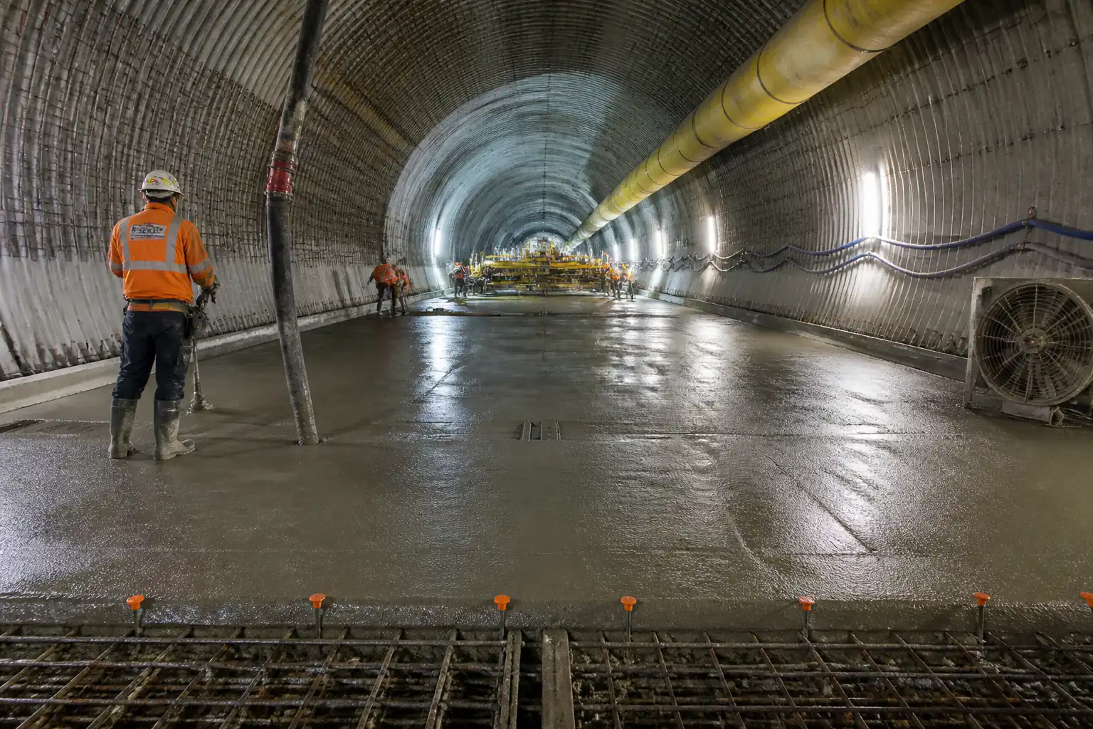

Method Statement: Invert Concrete Pour in Tunnel (Mass Concrete, Low-Heat Mix, Curved Formwork, Ventilation & Drainage Inserts) – Method Statement
AI-assisted method statement with matching ITP, PDF download, and Excel export.
More than a static template
Unlike a downloadable Word or PDF template, this method statement is an AI-assisted editable starting point connected directly to a matching Inspection and Test Plan. Every section is structured, project-adaptable, and ready to export.
- AI-assisted drafting — Customize every section with AI for your specific project scope.
- Linked ITP — A matching inspection and test plan is generated alongside the method statement.
- Multiple export formats — Download as a formatted PDF or editable Excel spreadsheet.
- Editable starting point, not a final document — Review, verify, and adjust all content against your project requirements before use.
Static template vs. Quollnet workflow
| Feature | Static template | Quollnet |
|---|---|---|
| Project-specific content | Manual fill-in required | AI-assisted customization |
| Linked ITP | Separate document, no link | Matching ITP included |
| Export formats | Usually PDF only | PDF and Excel |
| Structured sections | Free-form layout | 13 standardized sections |
| Saved to your account | Local file only | Cloud-saved, reusable |
| Content accuracy | You verify everything | AI-assisted, you still verify |
| Cost | Often free but time-intensive | Free to customize and download |
What you can customize
When you save this method statement to your account, every section becomes editable. The following 13 sections are included:
- Scope — Defines the activity and its boundaries.
- References — Standards, specifications, and drawings.
- Responsibilities — Roles and accountabilities.
- Resources — Labour, plant, and equipment summary.
- Materials — Materials and compliance requirements.
- Equipment — Tools and equipment details.
- Prerequisites — Hold points and pre-conditions.
- Method sequence — Step-by-step construction sequence.
- Safety controls — HSE risk controls and PPE.
- Environmental controls — Environmental mitigation measures.
- QA/QC — Quality inspection and test requirements.
- ITP — Inspection and Test Plan table (has its own page).
- Attachments — Referenced drawings and documentation.
Why this method statement is used
This method statement is used to define and communicate the approved procedure for carrying out method statement: invert concrete pour in tunnel (mass concrete, low-heat mix, curved formwork, ventilation & drainage inserts) on site. It ensures the work is planned in advance, the correct resources and controls are in place, and all personnel understand responsibilities, sequence, quality requirements, and safety controls before work begins. It aligns site execution with the documented scope and acceptance expectations.
Who uses this method statement
This method statement is used by contractors, site supervisors, project engineers, QA/QC engineers, HSE officers, consultants, and client representatives. It serves as a shared reference for planning, execution, supervision, inspection, and approval of the activity on site.
When it is prepared and submitted
The method statement is prepared before the work activity starts and submitted as part of the pre-construction documentation package for review and approval.
Who reviews or approves it
The method statement is usually submitted to the client representative, consultant, resident engineer, or project management consultant for review and approval before the work commences.
Important approval note
This method statement is an AI-assisted editable starting point, not a pre-approved document. Before use on any project, all content must be reviewed and approved by the relevant parties (superintendent, principal contractor, or client representative) in accordance with your contract and project quality plan.
For example: if your specification requires a departure from a referenced standard, that departure must be documented and approved separately — this method statement will not capture that automatically. Always verify against your applicable drawings, specifications, and regulatory requirements.
Method statement content
Scope
Overview
This method statement covers planning, preparation, placement, compaction, finishing, curing, and monitoring of mass concrete for the tunnel invert using a low-heat mix, curved formwork, and coordinated installation of drainage and ventilation inserts. It includes thermal control measures, ventilation management, confined space controls, and verification testing. It applies to segmental or cast-in-place primary linings where the invert slab/base is cast on prepared subgrade or on top of waterproofing/protection layers, as applicable.
Included Activities
- Survey and set-out of invert geometry and reference control.
- Subgrade proof-rolling and blinding (if required).
- Installation/verification of waterproofing protection layers (if present) and drainage elements (longitudinal/collector drains, sumps, weep holes, channels) and ventilation/MEP inserts.
- Erection, alignment, and bracing of curved formwork and bulkheads; installation of waterstops/hydrophilic strips at construction joints and penetrations.
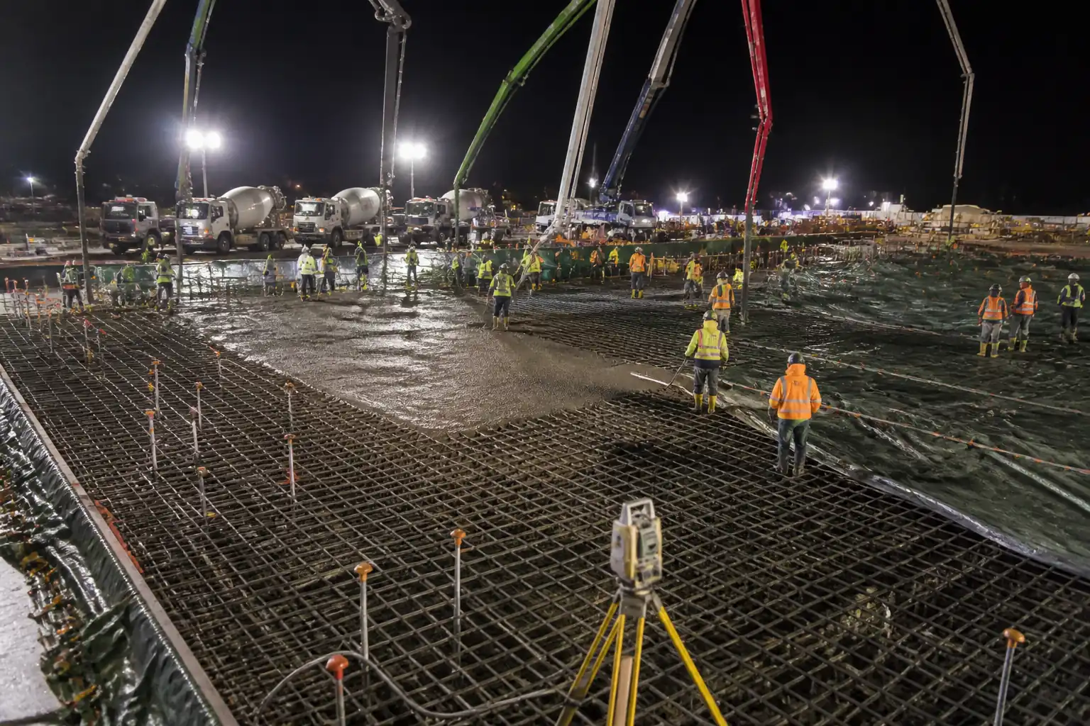
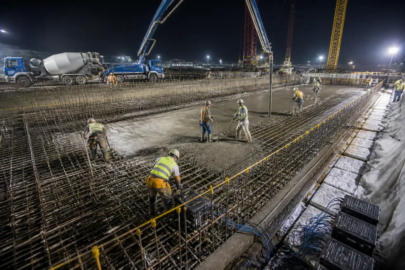
- Mass concrete production, delivery, pumping/placement, compaction, surface finishing, and curing with low-heat mix design and thermal control measures.
- Temperature monitoring (thermocouples/maturity sensors), early-age crack control measures, and controlled formwork striking.
- QA/QC inspections and tests, as-built survey, and demobilization.
Exclusions
- Permanent ventilation duct installation and commissioning beyond embedded base plates/inserts.
- Structural steelwork or embedded rail systems unless noted.
- Waterproofing membrane installation (if by others), except for protection/inspection interfaces.
Constraints & Interfaces
- Confined space entry, tunnel ventilation and air quality management.
- Coordination with MEP for ventilation inserts and with drainage design for invert gradient and outlets.
- Thermal behavior of mass concrete; pour size and rate limitations to control core and differential temperatures.
Key Performance Targets [Verify per project specifications]
- Invert line/level: ±10 mm.
- Gradient: within ±0.1% of design; no ponding >5 mm at any location.
- Surface regularity: 3 m straightedge deviation ≤10 mm.
- Concrete placement temperature: typically 10–25°C at discharge (project-specific).
- Maximum core temperature: typically ≤65–70°C; core-to-surface differential ≤20°C.
- 28-day compressive strength: as per design (e.g., 35–50 MPa typical).
References
| Document Type | Reference / Number | Revision | Notes |
|---|---|---|---|
| ACI 207.1R/207.2R/207.4R – Mass Concrete (thermal control, placement). | |||
| ACI 301 – Specifications for Structural Concrete (general requirements). | |||
| ACI 304R – Measuring, Mixing, Transporting, and Placing Concrete. | |||
| ACI 309R – Consolidation of Concrete (vibration). | |||
| ACI 305R (Hot Weather) and ACI 306R (Cold Weather) Concreting. | |||
| BS EN 206 / BS 8500 – Concrete specification and production [or local equivalent]. | |||
| EN 13670 – Execution of concrete structures; EN 1992-1-1 (Eurocode 2) where applicable. | |||
| BS 5975 – Temporary Works Procedures and the Permissible Stress Design of Falsework. | |||
| ASTM C94/C94M – Ready-Mixed Concrete; ASTM C150 – Portland Cement; ASTM C33 – Aggregates. | |||
| ASTM test methods: C39 (compressive strength), C143 (slump), C231 or C173 (air), C1064 (temperature), C138 (density), C172 (sampling). | |||
| Confined Space Entry requirements [Verify per project HSE plan and local regulations]. | |||
| Manufacturer data for formwork systems, waterstops, curing compounds, sensors/thermologgers. |
Responsibilities
| Role | Responsibility | Name / Party |
|---|---|---|
| PM | Project Manager | Contractor |
| CM | Construction Manager | Contractor |
| SE/Surveyor | Site Engineer / Surveyor | Contractor |
| QA/QC | QA/QC Engineer | Contractor |
| HSE | HSE Manager / Officer | Contractor |
| TWC | Temporary Works Coordinator (TWC) | Contractor |
| MEP/VENT/DRAIN | MEP Coordinator / Ventilation Engineer / Drainage Engineer | Contractor |
| Supplier | Ready-Mix Supplier | Vendor |
| Foreman | Formwork/Concrete Foreman | Contractor |
| Engineer | Engineer / Employer's Representative | Engineer |
Resources
| Resource Type | Description | Quantity | Remarks |
|---|---|---|---|
| Personnel | 1 CM, 1 Site Engineer, 1 QA/QC, 1 HSE, 1 Surveyor | 5 | |
| Personnel | 6–10 carpenters/formworkers + 1 crane/gantry operator | 7–11 | |
| Personnel | 1 pump operator, 6–8 laborers, 2–3 vibrators, 2 finishers | 11–14 | |
| Personnel | 1 MEP coordinator, 2 installers for inserts/channels | 3 |
Materials
| Material | Specification / Grade | Quantity | Remarks |
|---|---|---|---|
| Concrete | As per pour schedule | ||
| PVC/Bentonite | As per drawings | ||
| HDPE/PVC/Polymer concrete | As per BOQ | ||
| Steel | As per drawings | ||
| Various | Sufficient for 7 days+ | ||
| Various | As required | ||
| Sensors | Min. 4 sensors per pour block [Verify] |
Equipment
| Equipment | Capacity / Type | Quantity | Inspection Required |
|---|---|---|---|
| Formwork | As required | Yes | |
| Pump | 80–120 m³/h [Verify] | 1 pump + standby [Verify] | Yes |
| Vibrator | 2–3 + 1 spare | Yes | |
| Fans, monitors | Airflow per design [Verify] | As per calc | Yes |
| Survey/QA | 1 set | Yes | |
| Lighting | As required | Yes | |
| Pumps | As required | Yes |
Prerequisites
- Approved IFC drawings, method statement, and ITP.
- Approved concrete mix design (low-heat) with thermal control plan and pour sequence map.
- Temporary Works design/checks for formwork, bracing, and construction joints; Permit-to-Load/Strike regime in place.
- Confined space risk assessment; entry permit; rescue plan; ventilation calculations and equipment ready [Verify per project HSE plan and local regulations].
- Calibrated instruments (thermologgers, gas meters, survey equipment).
- MEP/ventilation/drainage coordination drawings with insert schedules; inspection of received materials.
- Waterproofing/protection layers installed and inspected (if applicable) with compatibility check for release agents and curing compounds.
- Pump line integrity/pressure test completed; washout management set up; spill kits available.
- Pre-pour coordination meeting and hold point with Contractor, Supplier, and Engineer to confirm sequence, crew, testing, and contingency measures.
- Access/egress, lighting, communications, and welfare arrangements confirmed.
Method Sequence
| Step | Activity | Description | Responsibility | Inspection / Hold Point |
|---|---|---|---|---|
| 1 | Survey & set-out | Install control points; set out invert alignment, grades, and joint locations. Mark insert positions and drainage features. | Site Engineer/Surveyor | ITP Hold Point: set-out verification |
| 2 | Subgrade preparation / blinding | Trim/proof-roll base; remove soft spots; place blinding (C8/10) if required for level and cleanliness. | Foreman / QA/QC | Visual, density (if compacted fill) |
| 3 | Waterproofing/protection check (if applicable) | Inspect installed waterproofing and protection board. Repair damage; ensure continuity at joints and penetrations. | QA/QC + Waterproofing Subcontractor | ITP Witness |
| 4 | Drainage installation | Install longitudinal drains, cross drains, sumps, channels, cleanouts, and outlets. Provide temporary protection/caps. | Drainage Team | Dimensional and gradient check |
| 5 | Ventilation/MEP inserts | Fix embedded base plates, sleeves, anchors per drawings. Provide templates/jigs to control position and plumb. | MEP Coordinator | Pre-pour check |
| 6 | Construction joints & waterstops | Install PVC waterstops and hydrophilic strips at joint bulkheads and penetrations. Secure against movement. | Formwork Foreman | Pre-pour |
| 7 | Curved formwork erection | Erect, align, and brace curved forms to design radius and grade; apply release agent compatible with waterproofing. | TWC/Formwork Foreman | TWC check; dimensional survey |
| 8 | Ventilation setup & air quality baseline | Install fans/ducts; establish airflow; baseline gas readings (O2/CO/NOx). | HSE/VENT Engineer | Confined Space Permit |
| 9 | Thermocouple installation | Install sensors at surface and core locations; fix leads clear of pour; verify logger operation. | QA/QC | Pre-pour check |
| 10 | Pre-pour inspection (Hold Point) | Joint checklist: formwork, inserts, drains, waterstops, cleanliness, access/egress, lighting, pump line secured. | QA/QC + Engineer | ITP Hold Point |
| 11 | Concrete delivery & verification | Receive concrete; check ticket; measure slump, temperature, air (if specified). Manage placement rate to reduce thermal peak. | QA/QC + Supplier | Continuous |
| 12 | Pumping/placement | Prime lines; place in layers ≤400 mm; maintain embedment position; avoid segregation; coordinate pour sequence to avoid cold joints. | Pump Operator/Foreman | Foreman/QA monitoring |
| 13 | Compaction | Internal vibration; insert vertically and withdraw slowly; avoid contact with waterstops/inserts. | Concrete Crew | QA observation |
| 14 | Finishing & surface tolerances | Screed to grade; float finish; check straightedge; form construction joints clean and keyed. | Finishers | Dimensional checks |
| 15 | Curing & thermal control | Apply curing compound or wet cover ASAP; insulate surface/side forms; monitor temperatures. | Foreman/QA | Daily |
| 16 | Formwork striking | Strike when strength/temperature criteria met; do not shock adjacent fresh concrete. | TWC/Formwork Foreman | Permit-to-Strike |
| 17 | Drainage functionality check | After initial set, perform water flow test through channels/outlets; check for ponding. | Drainage Team/QA | Witness |
| 18 | Testing & acceptance | Compressive strength tests; surface inspection; as-built survey; rectify defects. | QA/QC | Engineer review |
| 19 | Housekeeping & demobilization | Remove waste; manage washout; reinstate access; handover to next trade. | Foreman | HSE/QA walkdown |
Safety Controls
Principal Hazards and Controls
- Hazard: Confined space/tunnel environment with poor air quality (CO, NOx), low oxygen.
- Likely consequence: Asphyxiation, poisoning, loss of consciousness, fatality.
- Engineering/procedural control: Ventilation design with fans/ducting to achieve required airflow; continuous gas monitoring (O2, CO, NOx); establish air flow direction away from crew; limit diesel equipment; implement Confined Space Permit with attendant and communication; emergency rescue plan and stretcher on site. [Verify per project HSE plan and local regulations]
- Required PPE: Hard hat, hi-vis, gloves, eye protection; half-mask respirator if specified by monitoring; headlamp.
- Collective preventive measure: Fixed/portable ventilation, barriers to segregate equipment, signage.
-
Inspection/permit/supervision: Confined Space Entry Permit; hourly gas logs; HSE supervision.
-
Hazard: Concrete pump line failure/hose whipping under pressure.
- Likely consequence: Impact injuries, lacerations, concrete burns.
- Engineering/procedural control: Use steel pipeline with safety-clipped clamps; whip checks at hose; pressure test/inspection before pour; secure pipeline supports; exclusion zones at discharge; controlled priming and blow-out to washout container.
- PPE: Hard hat with face shield when near hose, gloves, waterproof boots.
- Collective: Physical barriers and spotters.
-
Inspection/permit: Pre-pour pump checklist; competent pump operator.
-
Hazard: Lifting/handling curved formwork and inserts.
- Likely consequence: Crush injuries, dropped objects.
- Control: Certified lifting points and gear; load test certificates; lifting plan and banksman; use gantry/rail trolleys; no standing under suspended loads.
- PPE: Hard hat with chin strap, safety boots, gloves.
- Collective: Exclusion zones, tag lines, barricades.
-
Inspection/permit: Lifting plan approval; daily crane/gear inspection.
-
Hazard: Trips/falls on uneven invert/base, open channels/sumps.
- Likely consequence: Sprains, fractures, immersion.
- Control: Good housekeeping; cover/protect openings; anti-slip walkways; adequate lighting (≥200 lux task lighting [Verify]).
- PPE: Ankle-supporting boots, headlamp.
- Collective: Edge protection, temporary covers.
-
Inspection/permit: HSE inspections; lighting checks.
-
Hazard: Vibration exposure from poker vibrators (HAVS).
- Likely consequence: Hand-arm vibration syndrome, numbness.
- Control: Use low-vibration tools, limit trigger time (work rotation), regular maintenance, warm-up exercises.
- PPE: Anti-vibration gloves (supplementary), hearing protection.
- Collective: Task rotation schedule.
-
Inspection/permit: HAVS monitoring logs.
-
Hazard: Cement/concrete contact (alkaline burns), curing compounds.
- Likely consequence: Chemical burns, dermatitis, eye injury.
- Control: Avoid skin contact; barrier creams; emergency wash stations; use low-VOC curing compounds; SDS briefing.
- PPE: Chemical-resistant gloves, goggles/face shield, long sleeves.
- Collective: Safety data sheets available; eyewash stations.
-
Inspection/permit: COSHH/chemical handling assessment.
-
Hazard: Noise from fans, pumps, vibrators.
- Likely consequence: Hearing damage, fatigue.
- Control: Noise assessment; select low-noise equipment; limit exposure; acoustic lining of ducts where feasible.
- PPE: Ear defenders (SNR per assessment).
- Collective: Signage of mandatory hearing protection zones.
-
Inspection/permit: Noise monitoring records.
-
Hazard: Rebar/insert impalement or cuts.
- Likely consequence: Lacerations, impalement.
- Control: Cap protruding bars; guard sharp edges; maintain clear access.
- PPE: Gloves, protective clothing.
- Collective: Physical barriers.
-
Inspection/permit: Daily pre-start checks.
-
Hazard: Electrical hazards from temporary power/lighting in damp tunnel.
- Likely consequence: Electric shock, fire.
- Control: 24–48 V task lighting; RCD protection; IP-rated equipment; cable management off floor; routine PAT.
- PPE: Dielectric gloves if working on panels (authorized persons only).
- Collective: Lock-out/tag-out.
-
Inspection/permit: Electrical permit-to-work when required.
-
Hazard: Water ingress/flooding during pour.
- Likely consequence: Drowning, equipment damage, segregation.
- Control: Active dewatering; standby pumps; high-water alarm; stop valves identified.
- PPE: Waterproof boots, flotation aids if required by risk assessment.
- Collective: Escape routes clear, muster points.
- Inspection/permit: Pre-pour water management plan review.
Environmental Controls
Key Environmental Risks and Mitigations
- Risk: Concrete washout and alkaline runoff.
- Impact: High pH discharge harming drains/watercourses.
- Control: Dedicated lined washout pits/containers; capture and neutralize water to pH 6–9 before disposal; no discharge to ground; sealed joints around channels during pour.
-
Monitoring: pH testing per load-out; visual inspections.
-
Risk: Slurry/mud tracking and siltation.
- Impact: Clogging of drainage/sumps, downstream pollution.
- Control: Silt curtains/screens in sumps; frequent cleaning; wheel-wash at portal; wet-vac for spills.
-
Monitoring: Daily housekeeping log.
-
Risk: Noise from fans/pumps at portal.
- Impact: Nuisance to receptors.
- Control: Acoustic enclosures/silencers; time restrictions; compliant equipment.
-
Monitoring: Noise level spot checks.
-
Risk: Air emissions (diesel exhaust, dust during prep).
- Impact: Air quality degradation.
- Control: Use electric equipment where practicable; Stage V/Tier 4 engines; regular maintenance; water mist for dust control; optimize ventilation flows.
-
Monitoring: Gas/dust measurements per HSE plan.
-
Risk: Waste from formwork, packaging, sensors.
- Impact: Resource depletion, improper disposal.
- Control: Segregated skips (timber/metal/plastic); recover reusable formwork; WEEE recycling for sensors/loggers.
-
Monitoring: Waste transfer notes, monthly reports.
-
Risk: Chemical use (release agents, curing compounds).
- Impact: Soil/water contamination, VOCs.
- Control: Low-VOC products; secondary containment; spill kits; trained users only.
-
Monitoring: SDS compliance checks.
-
Risk: Water abstraction/dewatering discharge.
- Impact: Potential permit breach.
- Control: Discharge via settlement tanks and pH control; permits in place; flow meters.
- Monitoring: Permit sampling frequency [Verify per local regulations].
QA/QC
Inspection and Testing
- Pre-pour inspections: formwork alignment, joint preparation, waterproofing/protection (if applicable), drainage and ventilation insert positions, cleanliness, access/lighting.
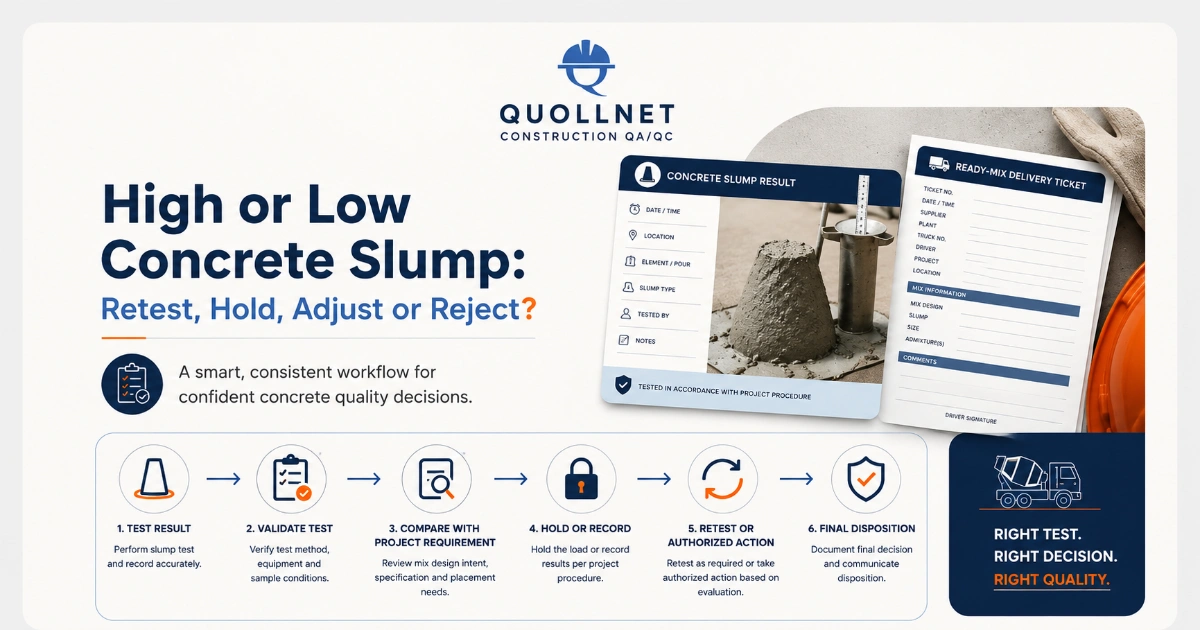
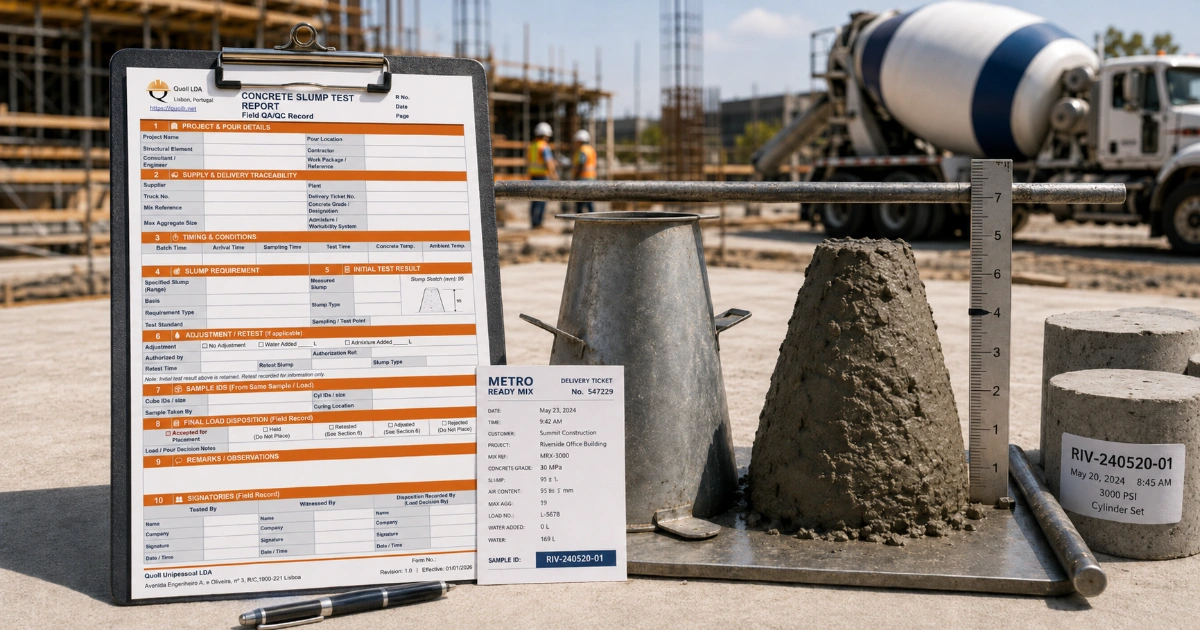
- Fresh concrete tests per delivery: sampling (ASTM C172), slump (ASTM C143), temperature (ASTM C1064), air content if specified (ASTM C231/C173), density (ASTM C138 if required).
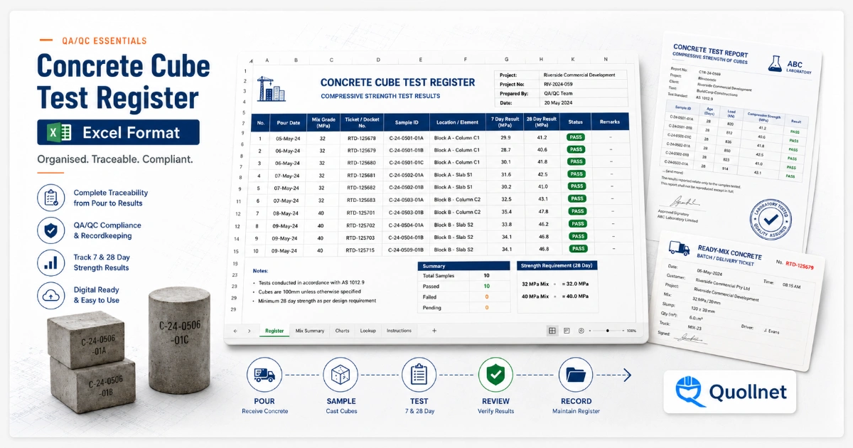
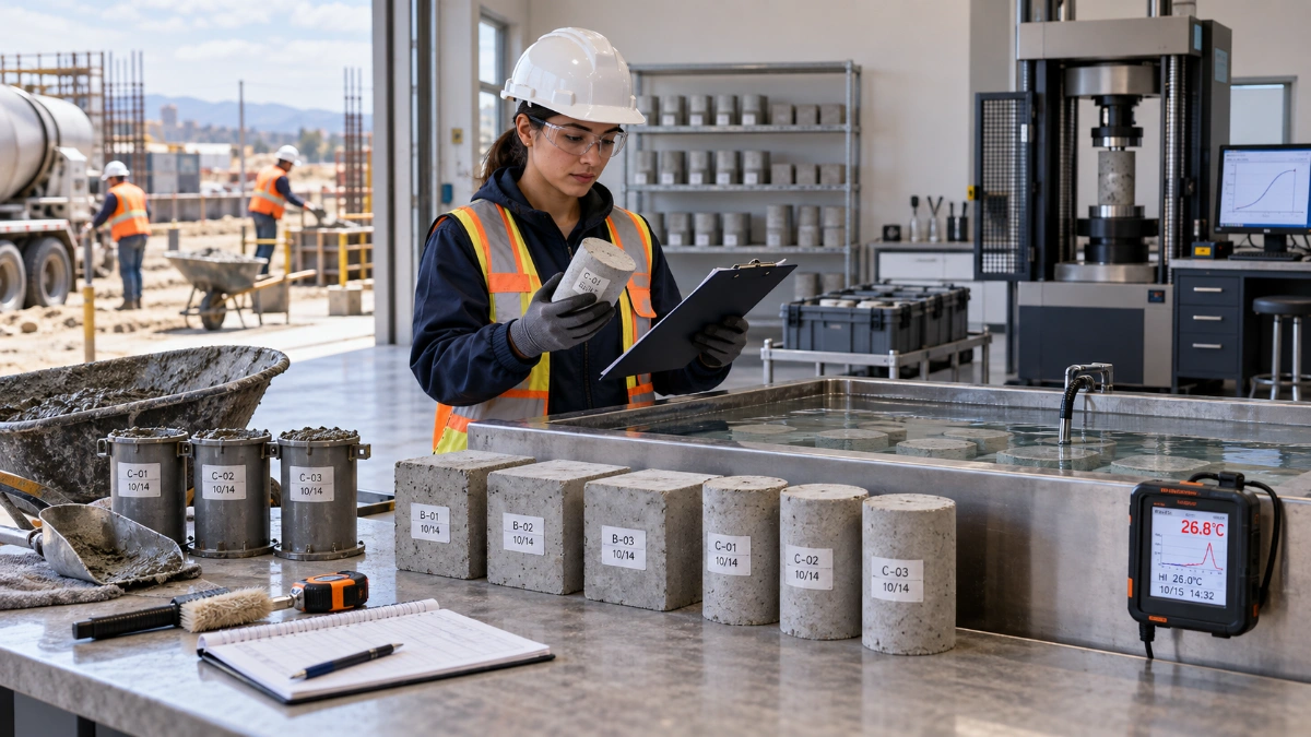
- Strength: 1 set of cylinders/cubes per 50 m³ placed or per pour, minimum 1 set/day [Verify]. Test at 7 and 28 days (ASTM C39 or EN 12390-3).
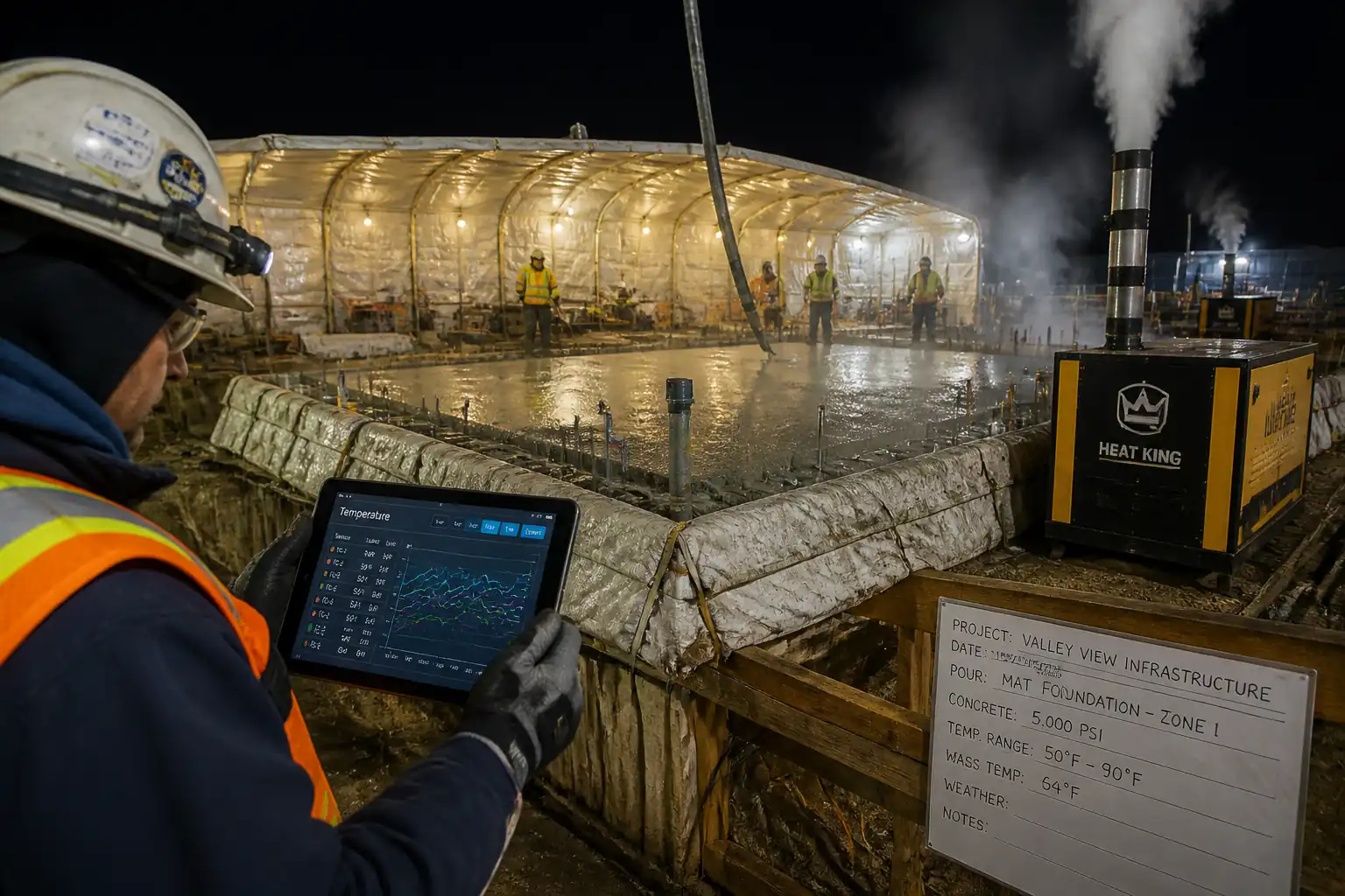
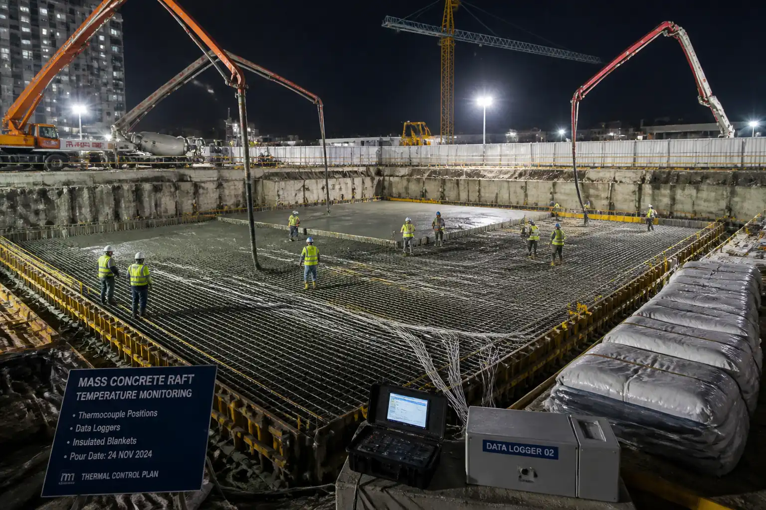
- Thermal monitoring: Minimum 4 thermocouples per pour block (surface and core) with 1–2 h logging interval for at least 7 days [Verify]. Review peak temperature and differential daily.
- Dimensional checks: levels, gradients, straightedge checks upon finishing and at 24 h.
- Drainage functionality: water/ball test per spec; confirm no ponding >5 mm and correct flow to outlets/sumps.
Acceptance Criteria [Verify per project specifications]
- Mix delivered within approved parameters; no unauthorized water addition.
- Slump: 75–125 mm (or per mix design tolerance). Temperature at discharge: typically 10–25°C.
- Thermal: core ≤65–70°C; core-surface ΔT ≤20°C.
- Strength: meets or exceeds design f'c at 28 days.
- Geometry: invert line/level ±10 mm; gradient within ±0.1%; surface deviation ≤10 mm over 3 m; edges true; joints neat with continuous waterstops.
- Surface: free of honeycombing/voids; finish per specification.
Documentation
- Approved mix design and thermal control plan; ITP and checklists; batch tickets; fresh and hardened concrete test reports; temperature logs; permits (Confined Space, Permit-to-Pour/Strike); inspection requests; as-built survey; NCRs/CARs (if any) and closeout reports.
Attachments
- Approved low-heat concrete mix design and thermal control plan.
- Formwork general arrangement drawings and TWC checks; permits to load/strike templates.
- Ventilation calculation, duct/fan layout, and gas monitoring plan; Confined Space Entry Permit template and rescue plan.
- Drainage and ventilation insert schedules and setting-out drawings.
- Inspection checklists: pre-pour, curing, finish/tolerances; ITP forms.
- Calibration certificates: survey equipment, thermologgers, gas monitors.
- Concrete supplier QA certificates and batch ticket template.
- Pump line inspection/pressure test record; hose whip-check installation guide.
- Environmental management plan: washout layout, pH neutralization procedure, spill response.
- Pour sequence map and joint details (including waterstops/hydrophilic strips).
- As-built survey template and closeout checklist.
This content is a read-only public reference. Download or customize to get an editable version.
ITP preview
The first inspection activities from the linked ITP for Method Statement: Invert Concrete Pour in Tunnel (Mass Concrete, Low-Heat Mix, Curved Formwork, Ventilation & Drainage Inserts):
| Activity | Inspection / Test | Acceptance Criteria | Responsibility | Record |
|---|---|---|---|---|
| Material approvals (concrete, waterstops, curing compounds, sensors) | Review certificates, mix design, SDS | Approved submittals and certificates current | QA/QC / Engineer | Submittal approvals, certificates |
| Survey set-out | Independent check of line/level | Within ±5 mm pre-forms [Verify] | Surveyor / Engineer | Survey report, IR |
| Subgrade/blinding inspection | Visual, level check; density test if applicable | Level ±10 mm; bearing/density per spec | QA/QC / Engineer | IR, test reports |
Showing 3 of 15 inspection activities. View full ITP →
Related Inspection and Test Plan
An Inspection and Test Plan (ITP) is available for Method Statement: Invert Concrete Pour in Tunnel (Mass Concrete, Low-Heat Mix, Curved Formwork, Ventilation & Drainage Inserts). The ITP defines the inspection activities, acceptance criteria, hold and witness points, responsible parties, and records required to verify the work described in this method statement.
View the Method Statement: Invert Concrete Pour in Tunnel (Mass Concrete, Low-Heat Mix, Curved Formwork, Ventilation & Drainage Inserts) ITP →Frequently asked questions
Continue with related Quollnet resources connected to this method statement.