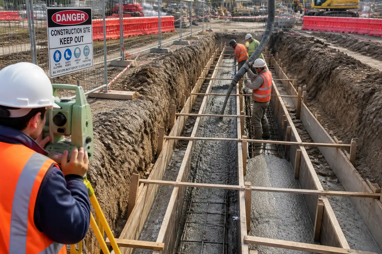
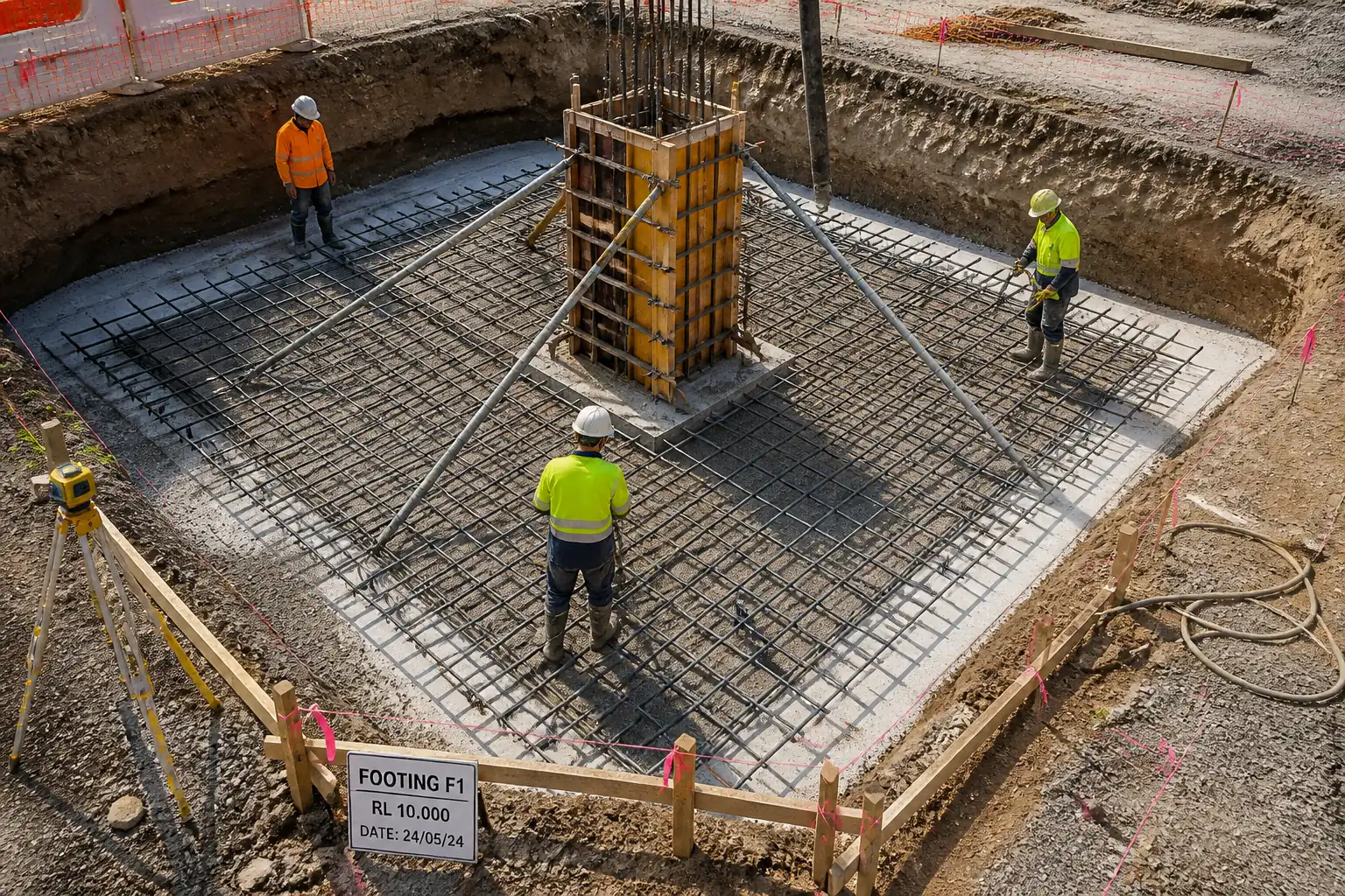
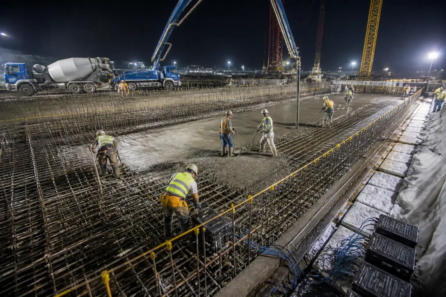
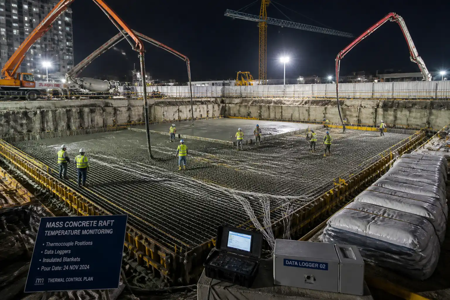
Inspection and Test Plan for Method Statement – Construction of Combined Footing Supporting Multiple Structural Columns
AI-assisted inspection and test plan connected to a method statement, with PDF and Excel export.
More than a static template
Unlike a downloadable Word or PDF template, this ITP is an AI-assisted editable starting point directly connected to its method statement. Every inspection activity, hold point, and acceptance criterion is structured and ready to adapt to your project.
- AI-assisted customization — Tailor inspection activities and acceptance criteria to your specific project scope.
- Linked method statement — This ITP is connected to the corresponding method statement describing the work sequence.
- Multiple export formats — Download as a formatted PDF or editable Excel spreadsheet.
- Editable starting point, not a final document — Review and verify all content against your project specifications and standards before use.
What you can customize
When you save this ITP to your account, every inspection row becomes editable. You can add, remove, or modify:
- Inspection activity — Description of what is being inspected.
- Inspection type — Hold point (H), Witness point (W), Review (R), or Monitor (M).
- Responsibility — Contractor, subcontractor, engineer, or client.
- Frequency — How often the inspection occurs.
- Acceptance criteria — Referenced standard or specification requirement.
- Records — Forms, test reports, or checklists required as evidence.
Why this ITP is used
To verify each stage of the combined footing meets design, standards, and project specifications with defined hold and witness points.
Who uses this inspection and test plan
QA/QC engineers, site engineers, supervising consultants, geotechnical engineers, and testing laboratories.
When this ITP is prepared and submitted
From pre-construction reviews through excavation, reinforcement, pouring, curing, and backfilling.
Who receives or approves this ITP
Engineer/Consultant for approval prior to works.
Inspection scope
Dimensional, material, process, and performance checks covering survey, subgrade quality, formwork stability, reinforcement details, concrete acceptance, and curing.
Typical hold, witness, and review points
Hold: founding level, reinforcement, embeds, pre-pour readiness. Witness: blinding, placing, level checks, thermal and curing inspections.
Typical inspection records
Inspection requests, test reports, batch tickets, curing/temperature logs, survey reports, photos, NCRs/close-outs.
Important approval note
This ITP is an AI-assisted editable starting point, not a pre-approved document. Before use on any project, all inspection activities, hold points, and acceptance criteria must be reviewed and approved by the relevant parties (superintendent, principal contractor, or client representative) in accordance with your contract and project quality plan.
Always verify acceptance criteria against your applicable drawings, specifications, and regulatory requirements. Hold points must be confirmed with the relevant authority before work proceeds past that point.
Inspection and test plan
| Activity | Inspection / Test | Acceptance Criteria | Responsibility | Record |
|---|---|---|---|---|
| Review of IFC drawings, MS & ITP | Document review | Approvals in place; latest revisions identified | QA/QC Engineer | Approval sheets, distribution matrix |
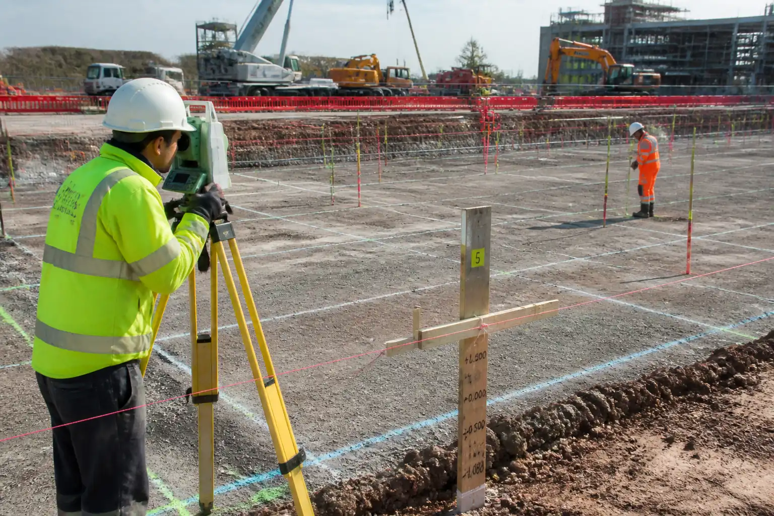
| Survey set-out of footing and grids | Instrument verification; set-out check | Grid and control points within ±5 mm | Surveyor | Set-out report, sketches |
| Excavation and founding level | Visual soil confirmation; RL check | Founding RL +0/−25 mm; suitable bearing stratum confirmed | Geotechnical Engineer / Site Engineer | Subgrade approval memo, photos |
| Subgrade compaction/proof-rolling | DCP/plate load/density (as specified) | ≥ 95% MDD or per geotechnical report [Verify] | QA/QC + Geotechnical | Test reports, IR |
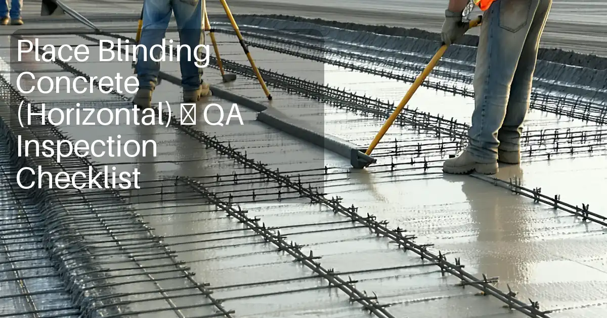
| Blinding concrete | Slump, temperature | Thickness 50–75 mm; slump/temperature within limits | QA/QC | Pour card, test results |
| Formwork and kicker inspection | Dimensional check; bracing check | ACI 117 tolerances; stability adequate | QA/QC + Engineer | Formwork checklist, IR |
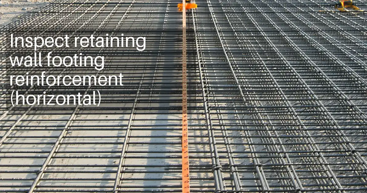
| Reinforcement – bottom mats and spacers | Cover gauge; spacing; cleanliness | Cover 75 mm [Verify]; spacing ±10 mm; laps per design | QA/QC | Rebar IR, photos |
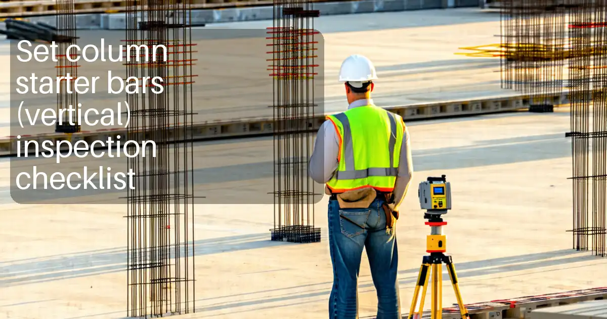
| Starters/anchors/couplers survey | Template measurement; torque (if couplers) | Position ±5 mm; verticality 1/1000; torque per manufacturer | Surveyor + QA/QC | Survey report, torque log |
| Reinforcement – top mats & congestion | Access for vibration; lap/coupler check | Vibrator access provided; bars secure; laps per design/AC I/EC2 | QA/QC + Engineer | Rebar IR |
| Pre-pour readiness | Checklist review | All holds cleared; pour authorization issued | QA/QC + HSE + Engineer | Signed checklist, pour permit |
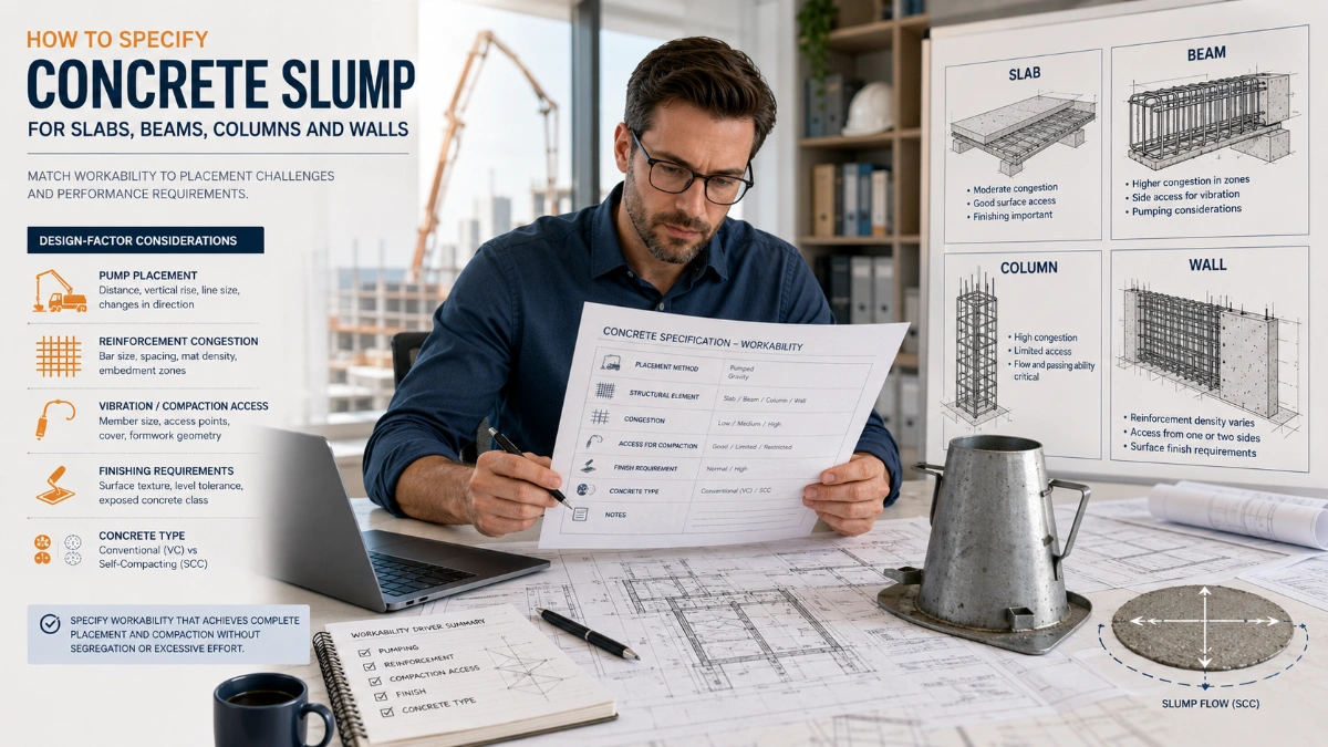
| Concrete acceptance tests (start and during) | C172, C143, C1064, C231/C138; cylinders/cubes C31/C39 | Results within specified ranges; specimens made and cured per standard | QA/QC | Test reports, lab receipts |
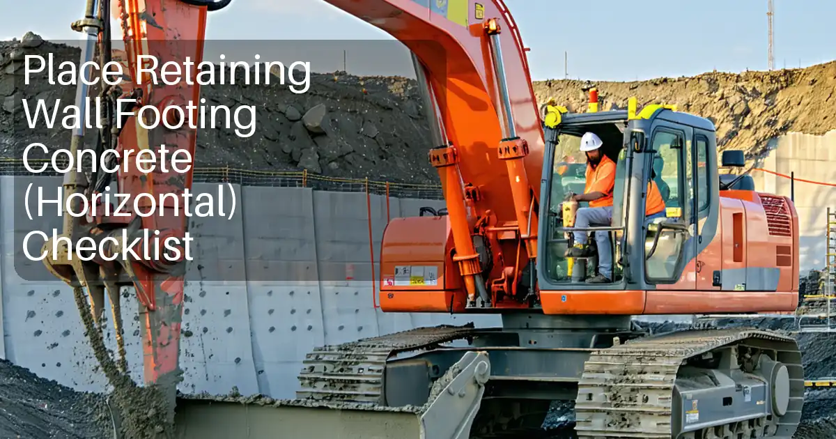
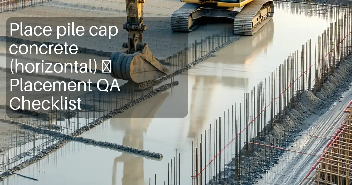
| Placing and vibration monitoring | Observation and records | No cold joints; adequate consolidation | Site Engineer/QA | Pour log, photos |
| Top level check after finishing | Laser level survey | Top surface ±10 mm of design | Surveyor/QA | Level survey sheet |
| Thermal monitoring | Sensor readings/logging | ΔT and Tmax within thermal plan limits [Verify] | QA/QC | Temperature logs |
| Curing compliance | Visual/record checks | Continuous curing ≥ 7 days or until 70% f’c [Verify] | Site Engineer/QA | Curing log, photos |
| Formwork striking inspection | Visual/hammer tap | Surfaces sound; defects repaired per spec | QA/QC + Engineer | IR, defect report |
| As-built survey (starters/anchors) | Instrument survey | Positions within ±5 mm; verticality 1/1000 | Surveyor | As-built report |
| Backfilling and compaction (if applicable) | Density test (D6938/D1556) | ≥ 95% MDD [Verify]; protection of foundation elements | Site Engineer/QA | Test results, IR |
This table is a read-only public reference. Download the PDF or Excel version, or customize this ITP to edit it for your project.
Frequently asked questions
Related method statement
This Inspection and Test Plan is associated with the Method Statement – Construction of Combined Footing Supporting Multiple Structural Columns method statement, which describes the step-by-step construction sequence, resources, materials, equipment, safety controls, and environmental controls for this activity.
View the Method Statement – Construction of Combined Footing Supporting Multiple Structural Columns method statement →Continue with related inspection, method statement, article, and checklist resources.