
Method Statement: Foundation & Footing Setting Out, Coordinate Verification, Offsets, Benchmarks, Tolerance Control, QA/QC and Hold Points – Method Statement
AI-assisted method statement with matching ITP, PDF download, and Excel export.
More than a static template
Unlike a downloadable Word or PDF template, this method statement is an AI-assisted editable starting point connected directly to a matching Inspection and Test Plan. Every section is structured, project-adaptable, and ready to export.
- AI-assisted drafting — Customize every section with AI for your specific project scope.
- Linked ITP — A matching inspection and test plan is generated alongside the method statement.
- Multiple export formats — Download as a formatted PDF or editable Excel spreadsheet.
- Editable starting point, not a final document — Review, verify, and adjust all content against your project requirements before use.
Static template vs. Quollnet workflow
| Feature | Static template | Quollnet |
|---|---|---|
| Project-specific content | Manual fill-in required | AI-assisted customization |
| Linked ITP | Separate document, no link | Matching ITP included |
| Export formats | Usually PDF only | PDF and Excel |
| Structured sections | Free-form layout | 13 standardized sections |
| Saved to your account | Local file only | Cloud-saved, reusable |
| Content accuracy | You verify everything | AI-assisted, you still verify |
| Cost | Often free but time-intensive | Free to customize and download |
What you can customize
When you save this method statement to your account, every section becomes editable. The following 13 sections are included:
- Scope — Defines the activity and its boundaries.
- References — Standards, specifications, and drawings.
- Responsibilities — Roles and accountabilities.
- Resources — Labour, plant, and equipment summary.
- Materials — Materials and compliance requirements.
- Equipment — Tools and equipment details.
- Prerequisites — Hold points and pre-conditions.
- Method sequence — Step-by-step construction sequence.
- Safety controls — HSE risk controls and PPE.
- Environmental controls — Environmental mitigation measures.
- QA/QC — Quality inspection and test requirements.
- ITP — Inspection and Test Plan table (has its own page).
- Attachments — Referenced drawings and documentation.
Why this method statement is used
This method statement is used to define and communicate the approved procedure for carrying out method statement: foundation & footing setting out, coordinate verification, offsets, benchmarks, tolerance control, qa/qc and hold points on site. It ensures the work is planned in advance, the correct resources and controls are in place, and all personnel understand responsibilities, sequence, quality requirements, and safety controls before work begins. It aligns site execution with the documented scope and acceptance expectations.
Who uses this method statement
This method statement is used by contractors, site supervisors, project engineers, QA/QC engineers, HSE officers, consultants, and client representatives. It serves as a shared reference for planning, execution, supervision, inspection, and approval of the activity on site.
When it is prepared and submitted
The method statement is prepared before the work activity starts and submitted as part of the pre-construction documentation package for review and approval.
Who reviews or approves it
The method statement is usually submitted to the client representative, consultant, resident engineer, or project management consultant for review and approval before the work commences.
Important approval note
This method statement is an AI-assisted editable starting point, not a pre-approved document. Before use on any project, all content must be reviewed and approved by the relevant parties (superintendent, principal contractor, or client representative) in accordance with your contract and project quality plan.
For example: if your specification requires a departure from a referenced standard, that departure must be documented and approved separately — this method statement will not capture that automatically. Always verify against your applicable drawings, specifications, and regulatory requirements.
Method statement content
Scope
Overview
This method statement covers all pre-concrete setting out and verification activities for foundations and footings, including:
- Establishment and verification of horizontal and vertical control (primary/secondary control points, TBMs) tied to project/grid datum.
- Coordinate verification against IFC drawings and approved setting-out data.
- Layout of foundation/footing centrelines, corners, and limits, including reference marks and excavation offsets.
- Installation of profile boards/batter boards and protection of survey markers.
- Tolerance control, dimensional checks, and QA/QC inspections.
- Hold/witness points for Engineer approval prior to excavation, after excavation (founding level), and prior to blinding/first concrete.
- Records generation: survey reports, control point register, raw data files, as-built deliverables.
Exclusions
- Structural reinforcement setting out and anchor bolt installation (covered under separate method statements if required).
- Concrete placement and curing (refer to concrete works method statement).
Interfaces
- Geotechnical investigation and founding level acceptance.
- Excavation works sequencing and shoring design.
- Utilities detection/clearance where stakes/profile boards may conflict with existing services.
References
| Document Type | Reference / Number | Revision | Notes |
|---|---|---|---|
| Standard | ISO 4463-1 [Verify latest edition] | ||
| Standard | BS 5606 [Verify latest edition] | ||
| Standard | ACI 117, ACI 301 [Verify applicable edition] | ||
| Standard | ISO 17123-2/-3/-8 as applicable [Verify latest editions] | ||
| Standard/Guideline | ASCE/CI 38-22 or PAS 128 [Project dependent] | [Verify per project specifications] | |
| Contract Docs | |||
| Standard | ISO 9001; ISO/IEC 17025 for calibration traceability |
Responsibilities
| Role | Responsibility | Name / Party |
|---|---|---|
| Project Manager | Ensure method/ITP approval, staffing, and schedule integration. | Contractor |
| Survey Manager | Approves control network design, checks adjustments, sets tolerances and check frequencies. | Contractor |
| Senior Land Surveyor | Daily instrument checks, layout, offset/profile installation, red/blue check. | Contractor |
| Assistant Surveyor | Implements safety zones, protects markers. | Contractor |
| QA/QC Engineer | Witness/hold point coordination with Engineer. | Contractor |
| HSE Supervisor | Permit-to-dig, exclusion zones, supervision. | Contractor |
| Engineer | Approve control network, setting-out prior to excavation/blinding. | Engineer |
Resources
| Resource Type | Description | Quantity | Remarks |
|---|---|---|---|
| Personnel | Survey Manager, Senior Surveyor, Assistant Surveyor, QA/QC Engineer, HSE Supervisor, Site Engineer. | As required | |
| Software | Survey computation and CAD software for coordinate calculations and as-builts. | As required |
Materials
| Material | Specification / Grade | Quantity | Remarks |
|---|---|---|---|
| Concrete/grout | [Verify per project] | As required | |
| Treated timber | Outdoor grade | As required | |
| Paint/chalk | Low-VOC where practicable | As required |
Equipment
| Equipment | Capacity / Type | Quantity | Inspection Required |
|---|---|---|---|
| 2 (1 working + 1 check) [Verify] | |||
| 1–2 | |||
| 1 set | |||
| As required |
Prerequisites
- Approved method statement and ITP.
- Latest IFC drawings, grid coordinates, control data files, and vertical datum information.
- Calibration certificates (ISO/IEC 17025) for instruments valid and filed.
- Permit-to-dig and utility clearance where staking/profiling involves ground penetration. Perform desktop utility review and, if required, GPR/EML scans.
- Risk Assessment and Method Statement (RAMS) briefing and toolbox talk completed; exclusion zones planned.
- Survey computation files prepared and independently checked (red/blue check) including transformation parameters if any.
- Access, platforms, and safe working area established and illuminated if working in low light.
- Weather assessed: avoid high winds affecting instrument stability and heat shimmer causing refraction; implement timing controls as needed.
- Coordination with excavation team on sequence and protection of markers.
- Engineer notified for planned hold/witness points with sufficient notice per contract.
Method Sequence
| Step | Activity | Description | Responsibility | Inspection / Hold Point |
|---|---|---|---|---|
| 1 | Design/Data Review and Survey Plan | Review IFC drawings, grid/datum definitions, geotechnical report, and project tolerances. Prepare Survey Execution Plan including accuracy classes, check frequencies, and deliverables. | Survey Manager / Senior Surveyor | Document review |
| 2 | Instrument Checks and Calibration Verification | Verify calibration certificates. Perform daily checks: total station collimation, prism constants, EDM baseline; level two-peg test; GNSS health/PDOP forecast if used. | Senior Surveyor | Daily instrument log |
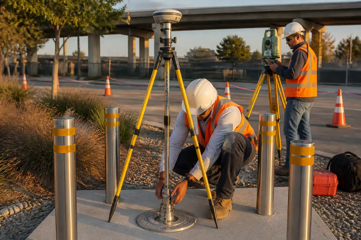
| 3 | Establish Primary Control Network | Install durable control points tied to project/national grid and TBMs for vertical datum. Use redundant observations (at least 2 backsights/foresights). Protect and georeference points. | Senior Surveyor | Witness by QA/QC |
| 4 | Protection of Control | Erect barriers/boxes for control points; record offsets and ties; add signage and GIS references. Create recovery sketches with photos and coordinates. | Senior Surveyor / HSE | HSE/QA inspection |
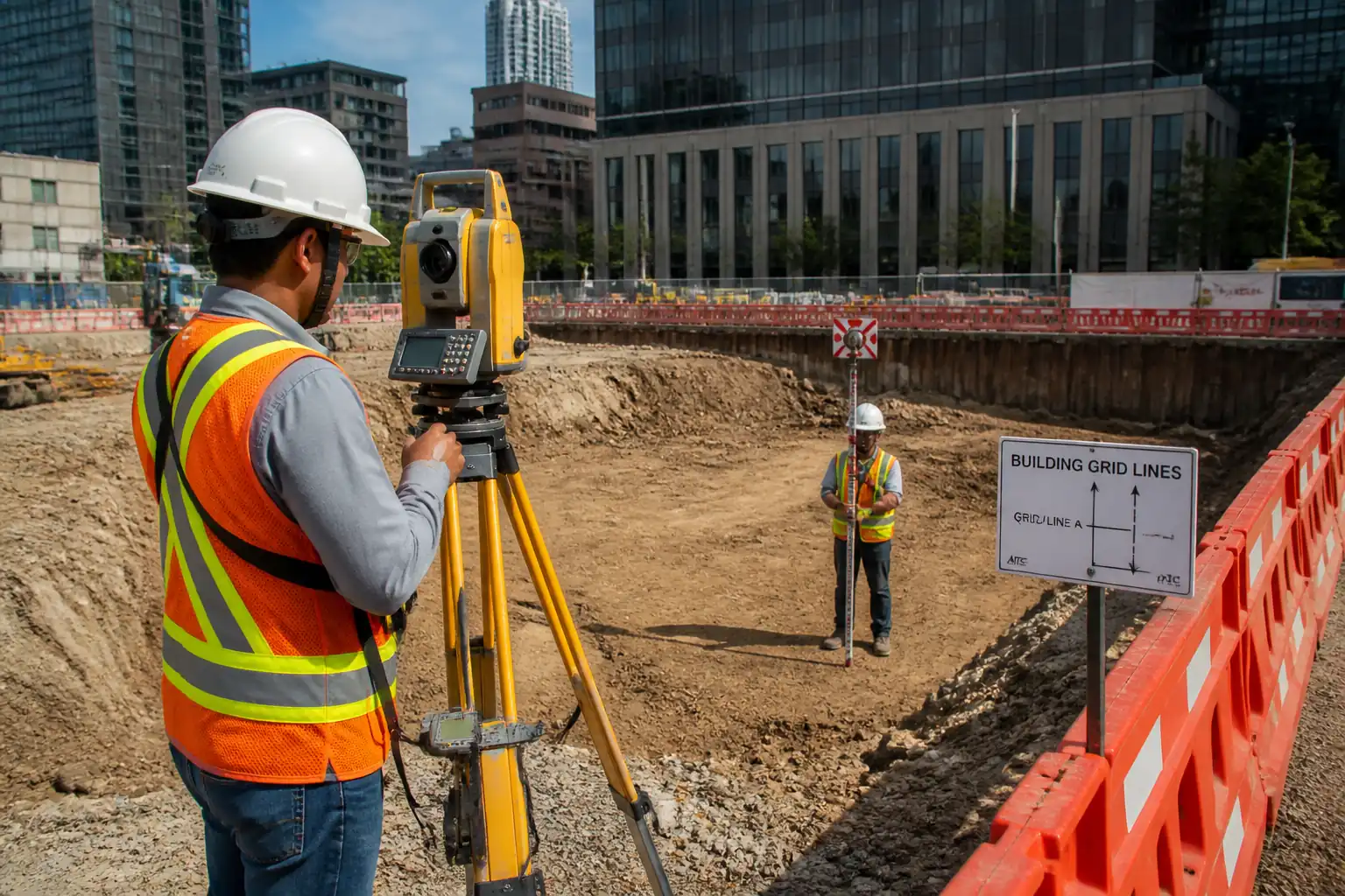
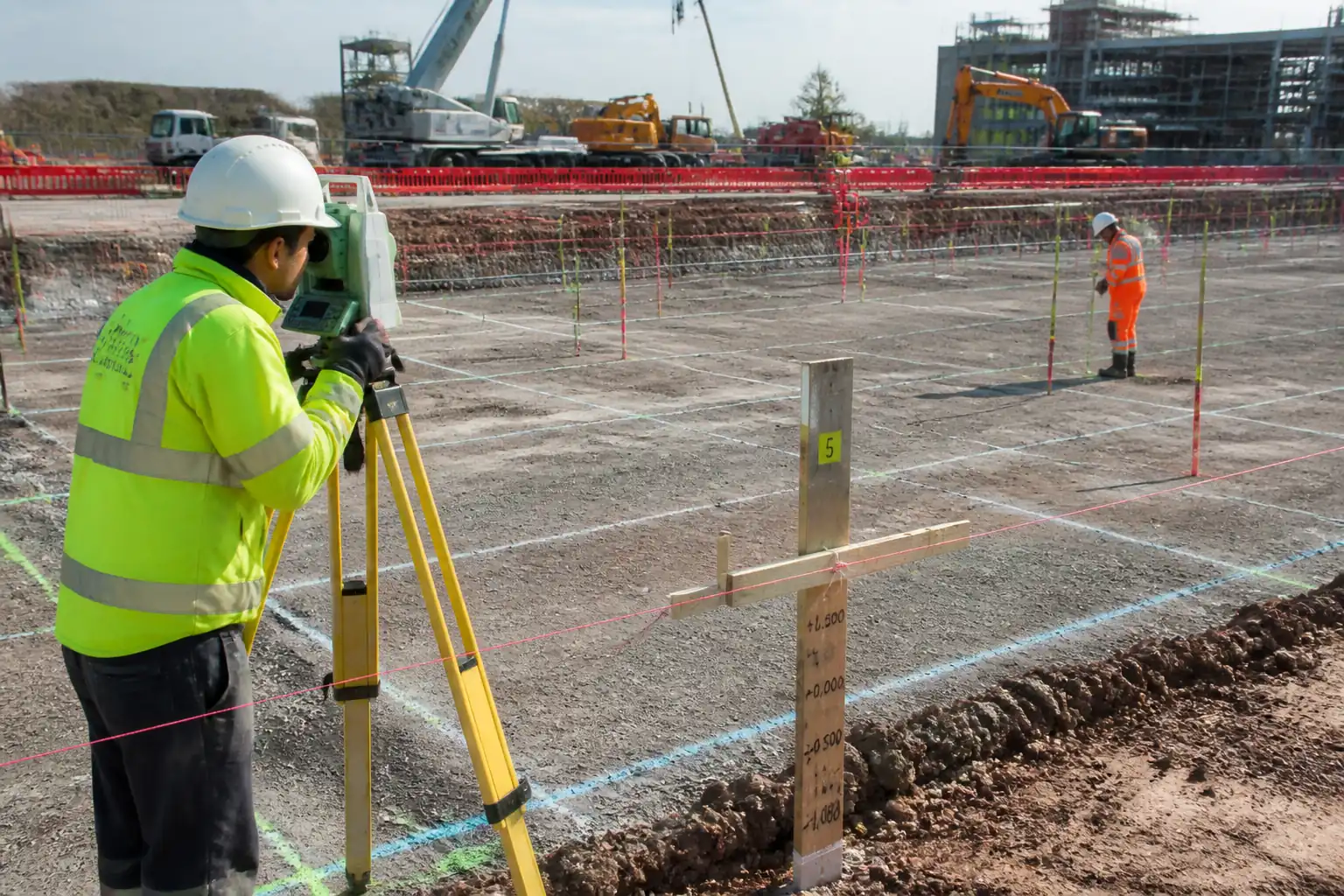
| 5 | Set Out Foundation/Footing Grid Lines | Using total station, set and mark grid intersections and key points (corners, centerlines). Mark with nails/paint; establish reference marks outside excavation line. | Senior Surveyor | Internal check |
| 6 | Install Profile Boards (Batter Boards) and Offsets | Install rigid profile boards typically 1.0–1.5 m outside excavation. Transfer grid/footing lines to nails on cross-members; set elevation references for blinding/top of footing as required. | Senior Surveyor / Site Engineer | QA/QC witness |
| 7 | Hold Point: Pre-Excavation Setting-Out Approval | Submit IR with setting-out drawings and control report for Engineer’s review. Walkdown to confirm locations, offsets, and protections before excavation begins. | QA/QC Engineer / Senior Surveyor | Engineer Hold Point HP-1 |
| 8 | Excavation Monitoring and Control | Provide cut/fill stakes or profiles indicating excavation limits/depth. Check excavation progress and maintain reference lines. Re-establish markers if disturbed. | Senior Surveyor / Site Engineer | Ongoing |
| 9 | Post-Excavation Survey and Founding Level Verification | Survey bottom of excavation and footing platforms; confirm founding levels and bearing stratum per geotechnical requirements. Update as-built model/drawings. | Senior Surveyor / Geotechnical Rep (as applicable) | Engineer Witness W-2 |
| 10 | Set Out Blinding Level and Final Line Checks | Transfer finished blinding levels to profiles/pins; verify footing extents and squareness/orthogonality using diagonals and angle checks. | Senior Surveyor | Internal check + QA/QC |
| 11 | Hold Point: Pre-Blinding/Pre-Concrete Dimensional Approval | Submit IR with survey as-built of excavation platform and blinding levels for Engineer approval prior to blinding/first concrete. | QA/QC Engineer | Engineer Hold Point HP-2 |
| 12 | Records and Handover | Compile Daily Survey Reports, control point register, instrument logs, IR approvals, as-built files (CSV/DWG/PDF), photos, and update document control system. | Survey Manager / QA/QC | QA audit |
Health, Safety, and Environment (HSE) – Safety Controls
Key Task-Specific Hazards and Controls
1) Hazard: Underground utility strike during staking/profile installation
- Likely consequence: Electric shock, gas release, service outage, injury/fatality
- Engineering/procedural control: Permit-to-dig; review utility records; GPR/EML scanning where uncertainty exists; hand-dig only within tolerance zones; use insulated tools; depth-controlled stakes
- Required PPE: Class E helmet, arc-rated gloves where electrical risk, safety boots, eye protection
- Collective measure: Mark exclusion zones, spotter present, barriers
- Inspection/permit/supervision: Approved PTW, utility scan reports, HSE supervision [Verify per project HSE plan and local regulations]
2) Hazard: Falls into excavation or from unstable edges during setting out
- Likely consequence: Serious injury from falls, entrapment
- Engineering/procedural control: Edge protection or barriers ≥1.1 m; safe access/egress (ladders/ramps); maintain minimum 1.0 m set-back for profiles; comply with shoring design
- PPE: Helmet with chin strap, high-visibility vest, boots
- Collective measure: Physical barriers, designated walkways
- Inspection/permit/supervision: Daily excavation inspection by competent person; records retained
3) Hazard: Plant–personnel interface (excavators, loaders) near survey operations
- Likely consequence: Struck-by, crushed
- Engineering/procedural control: Segregate work zones, radio comms with operator, use spotter, eye contact rule, no entry to slew radius without lock-out
- PPE: High-visibility clothing, boots, gloves
- Collective measure: Temporary traffic management and exclusion zones
- Inspection/permit/supervision: Supervisor coordination, permit to work where required
4) Hazard: Instrument instability and tripod toppling in high wind/uneven ground
- Likely consequence: Equipment strike, loss of control accuracy, damage
- Engineering/procedural control: Use spiked feet, sandbags, low tripod stance; suspend operations above defined wind limits [Verify]; double-observe to mitigate refraction
- PPE: Gloves, eye protection
- Collective measure: Controlled access around instrument setup
- Inspection/permit/supervision: Supervisor verification of environmental limits
5) Hazard: Manual handling of profiles, stakes, and equipment
- Likely consequence: Musculoskeletal injuries, cuts
- Engineering/procedural control: Team lifts, mechanical aids where feasible, cut-resistant gloves, pre-cut timber to manageable lengths
- PPE: Gloves, boots, long sleeves
- Collective measure: Manual handling training and rotation to avoid fatigue
- Inspection/permit/supervision: HSE monitoring of lifting practices
6) Hazard: Slips, trips, and sharp objects (nails, rebar, debris)
- Likely consequence: Puncture wounds, falls
- Engineering/procedural control: Good housekeeping; cap exposed rebar; remove protruding nails or bend over; maintain tidy profile areas
- PPE: Safety boots with midsole protection, gloves, eye protection
- Collective measure: Site housekeeping regime, waste bins
- Inspection/permit/supervision: Daily supervisor walkdowns
7) Hazard: Eye/skin exposure to marking paint and sun/heat stress
- Likely consequence: Irritation, heat illness
- Engineering/procedural control: Low-VOC paints; shade breaks; hydration plan; schedule in cooler hours
- PPE: Safety glasses, sun protection (SPF), lightweight hi-vis
- Collective measure: Welfare provisions, potable water stations
- Inspection/permit/supervision: HSE checks, first-aid readiness
8) Hazard: Laser exposure from total station
- Likely consequence: Eye injury
- Engineering/procedural control: Do not look into EDM/laser; use Class 1 instruments where possible; display laser warning signs
- PPE: None beyond standard unless specified by manufacturer
- Collective measure: Marked instrument area
- Inspection/permit/supervision: Compliance with manufacturer and project HSE
[All controls to be verified per project HSE plan and local regulations.]
Environmental Controls
- Use biodegradable, low-VOC marking paints where feasible; avoid overspray to vegetation and drains.
- Manage timber waste from profile boards: reuse where possible; segregate and dispose via approved waste stream. Remove all temporary stakes/profiles when no longer required.
- Prevent silt run-off into drainage from disturbed areas near excavation; install silt fences or straw wattles if rainfall forecast.
- Noise and working hours: avoid night-time works unless permitted; maintain equipment and use rubber mallets where practicable to reduce impact noise.
- Spill prevention: keep paints, fuels, and lubricants in secondary containment; refuel away from watercourses.
- Battery and e-waste from survey instruments to be collected and recycled via approved vendors.
- Light pollution: use directional, low-glare task lighting for any low-light survey works; turn off when not in use.
- Archaeological or heritage markers: if encountered, stop work and notify Engineer/Authorities. [Verify per project ESMP].
Quality Assurance / Quality Control
QA/QC Strategy
- Apply ISO 9001 controls and maintain traceability from raw survey observations to issued drawings.
- Use independent check (red/blue) for coordinate computations and setting-out values before site marking.
- Ensure all instruments have current ISO/IEC 17025 calibration and daily field checks recorded.
- Control network designed with redundancy; perform least squares adjustment; document residuals and uncertainties.
- Each critical set-out (grid lines, footing corners) to be independently checked by a second surveyor prior to hold point submissions.
Typical Acceptance Criteria [Verify per project specifications]
- Network adjustment residuals: H ≤ 5 mm; V closure ≤ ±4√K mm (K in km) for levelling loops.
- Plan position at footing corners/centrelines: ±10–20 mm typical.
- Blinding level: ±5–10 mm typical.
- Orthogonality and diagonals: angle error ≤ 10–20 arcsec; diagonal difference within ±10–15 mm typical.
- Excavation depth relative to design founding level: ±50 mm typical unless geotechnical criteria dictate tighter control.
Records
- Survey Control Report; Control Point Register with photos and protection details.
- Daily Survey Reports with weather, instrument IDs, checks, observations summary, and sketches.
- IRs and Engineer approvals at hold points.
- As-built deliverables (CSV/XYZ, CAD/DWG, PDF sketches), level sheets, profile board register.
- Nonconformance Reports (NCR) and Corrective Actions where deviations exceed tolerance.
Nonconformance and Corrective Action
- If tolerance exceedance detected, stop related work, mark the area, notify QA/QC and Engineer, investigate root cause (instrument, control, computation, execution), re-establish control if required, and re-survey after correction.
Change Control
- Any design or grid/datum change to be formally received, logged, and verified; re-issue set-out data and notify stakeholders; supersede old marks and drawings to avoid use of obsolete data.
Attachments
- Template: Survey Control Point Register (with photo log)
- Template: Daily Survey Report and Instrument Check Log
- Sample: Setting-Out Calculation Sheet (checked)
- Sample: Profile Board Register and Level Sheet
- IR Templates for HP-1 (Pre-excavation) and HP-2 (Pre-blinding)
- Example: As-built CSV and DWG deliverables schema
- Copy of calibration certificates (ISO/IEC 17025) for instruments
- Risk Assessment & Method Statement (RAMS) for survey works
- Utility clearance records and PTW (if applicable)
- Geotechnical acceptance memo template for founding level
This content is a read-only public reference. Download or customize to get an editable version.
ITP preview
The first inspection activities from the linked ITP for Method Statement: Foundation & Footing Setting Out, Coordinate Verification, Offsets, Benchmarks, Tolerance Control, QA/QC and Hold Points:
| Activity | Inspection / Test | Acceptance Criteria | Responsibility | Record |
|---|---|---|---|---|
| Review and approval of Survey Execution Plan (SEP) and setting-out calculations | Independent calc check | SEP approved; no discrepancies | Survey Manager / QA-QC / Engineer | Approved SEP, calc check sheet |
| Instrument calibration and daily field checks | ISO 17123 procedures | Within allowable instrument limits | Senior Surveyor / QA-QC | Calibration certs; daily logs |
| Establishment of primary/secondary control points and TBMs | Network adjustment, closure checks | Residuals within project limits [Verify] | Senior Surveyor / QA-QC / Engineer (Witness) | Control report; register; photos |
Showing 3 of 9 inspection activities. View full ITP →
Related Inspection and Test Plan
An Inspection and Test Plan (ITP) is available for Method Statement: Foundation & Footing Setting Out, Coordinate Verification, Offsets, Benchmarks, Tolerance Control, QA/QC and Hold Points. The ITP defines the inspection activities, acceptance criteria, hold and witness points, responsible parties, and records required to verify the work described in this method statement.
View the Method Statement: Foundation & Footing Setting Out, Coordinate Verification, Offsets, Benchmarks, Tolerance Control, QA/QC and Hold Points ITP →Frequently asked questions
Continue with related Quollnet resources connected to this method statement.