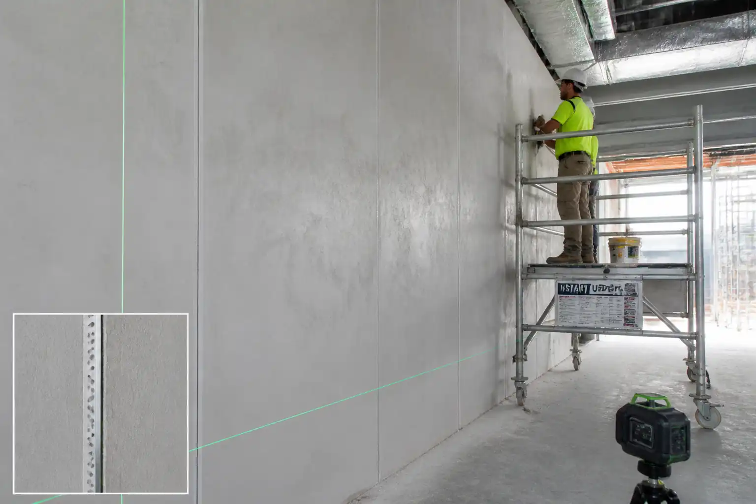

Method Statement: Installation of Plaster Control Joints – Method Statement
AI-assisted method statement with matching ITP, PDF download, and Excel export.
More than a static template
Unlike a downloadable Word or PDF template, this method statement is an AI-assisted editable starting point connected directly to a matching Inspection and Test Plan. Every section is structured, project-adaptable, and ready to export.
- AI-assisted drafting — Customize every section with AI for your specific project scope.
- Linked ITP — A matching inspection and test plan is generated alongside the method statement.
- Multiple export formats — Download as a formatted PDF or editable Excel spreadsheet.
- Editable starting point, not a final document — Review, verify, and adjust all content against your project requirements before use.
Static template vs. Quollnet workflow
| Feature | Static template | Quollnet |
|---|---|---|
| Project-specific content | Manual fill-in required | AI-assisted customization |
| Linked ITP | Separate document, no link | Matching ITP included |
| Export formats | Usually PDF only | PDF and Excel |
| Structured sections | Free-form layout | 13 standardized sections |
| Saved to your account | Local file only | Cloud-saved, reusable |
| Content accuracy | You verify everything | AI-assisted, you still verify |
| Cost | Often free but time-intensive | Free to customize and download |
What you can customize
When you save this method statement to your account, every section becomes editable. The following 13 sections are included:
- Scope — Defines the activity and its boundaries.
- References — Standards, specifications, and drawings.
- Responsibilities — Roles and accountabilities.
- Resources — Labour, plant, and equipment summary.
- Materials — Materials and compliance requirements.
- Equipment — Tools and equipment details.
- Prerequisites — Hold points and pre-conditions.
- Method sequence — Step-by-step construction sequence.
- Safety controls — HSE risk controls and PPE.
- Environmental controls — Environmental mitigation measures.
- QA/QC — Quality inspection and test requirements.
- ITP — Inspection and Test Plan table (has its own page).
- Attachments — Referenced drawings and documentation.
Why this method statement is used
This method statement is used to define and communicate the approved procedure for carrying out method statement: installation of plaster control joints on site. It ensures the work is planned in advance, the correct resources and controls are in place, and all personnel understand responsibilities, sequence, quality requirements, and safety controls before work begins. It aligns site execution with the documented scope and acceptance expectations.
Who uses this method statement
This method statement is used by contractors, site supervisors, project engineers, QA/QC engineers, HSE officers, consultants, and client representatives. It serves as a shared reference for planning, execution, supervision, inspection, and approval of the activity on site.
When it is prepared and submitted
The method statement is prepared before the work activity starts and submitted as part of the pre-construction documentation package for review and approval.
Who reviews or approves it
The method statement is usually submitted to the client representative, consultant, resident engineer, or project management consultant for review and approval before the work commences.
Important approval note
This method statement is an AI-assisted editable starting point, not a pre-approved document. Before use on any project, all content must be reviewed and approved by the relevant parties (superintendent, principal contractor, or client representative) in accordance with your contract and project quality plan.
For example: if your specification requires a departure from a referenced standard, that departure must be documented and approved separately — this method statement will not capture that automatically. Always verify against your applicable drawings, specifications, and regulatory requirements.
Method statement content
Scope
Overview
This method statement covers the supply, layout, installation, alignment, and inspection of plaster control joints (preformed beads/trims) in interior plaster systems and external render/stucco where specified. It includes verification of joint locations, substrate/interface coordination, crack mitigation strategy, QA/QC hold points, and final inspection prior to finishes (paint, wallpaper, etc.).
Inclusions
- Review and confirmation of joint layout per drawings and standards.
- Material receipt, storage, and verification of accessories (metal/PVC/stainless) and sealants.
- Installation of control joints in new plaster works, including discontinuity of lath (where applicable), fixing, alignment, and sealant/backer rod where movement joints are required.
- Coordination with adjacent trades (framing, MEP, doors/windows, fire-stopping, acoustic seals).
- Intermediate and final inspections, documentation, and as-built updates.
Exclusions
- Structural movement joint design and waterproofing membranes (by others).
- Primary substrate construction (concrete, blockwork, framing) except local preparation for joint installation.
- Painting/finishing beyond ensuring joints are ready for finishes.
References
| Document Type | Reference / Number | Revision | Notes |
|---|---|---|---|
| Standard | ASTM C1063 | Applicable where metal lath or stucco/render is used. | |
| Standard | ASTM C926 | ||
| Standard | ASTM C1047 | Where gypsum-based plaster systems/accessories are specified. | |
| Standard | ASTM C841 | ||
| Standard | BS EN 13914-1 | Where Euro/UK standards apply. | |
| Standard | BS EN 13914-2 | ||
| Report | ACI 224R | For coordinating plaster control joints with substrate joints. | |
| Standard | ASTM C920 / ISO 11600 | Select sealant class per movement capability required. | |
| MDS | Per approved submittals | Follow latest approved submittal; supersedes generic guidance where applicable. | |
| Contract | Per Contract | Prevailing over standards in case of conflict, unless code-mandated. |
Responsibilities
| Role | Responsibility | Name / Party |
|---|---|---|
| PM | Ensure compliance with contract and standards. | Contractor |
| CM/Supt. | Daily supervision and progress. | Contractor |
| SE | Control joint locations and alignment. | Contractor |
| QA/QC | Enforce hold/witness points and acceptance criteria. | Contractor |
| HSE | Ensure task-specific controls and PPE. | Contractor |
| Surveyor | Provide benchmarks and quality of set-out. | Contractor |
| Foreman | Correct installation per approved method. | Contractor |
| Storekeeper | Prevent damage/corrosion and maintain traceability. | Contractor |
| TPI | Sign-off critical stages. | Third Party |
| Consultant | Issue approvals and instructions. | Engineer |
Resources
| Resource Type | Description | Quantity | Remarks |
|---|---|---|---|
| Manpower | Install control joints and apply plaster. | 1 crew/300–500 m²/week [Verify] | |
| Manpower | Install backer rods and sealants where required. | As needed | |
| Manpower | Setting-out and verification. | 1 team per active floor | |
| Manpower | Provide safe access and platforms. | As required |
Materials
| Material | Specification / Grade | Quantity | Remarks |
|---|---|---|---|
| Metal/PVC | Length 2.4–3.0 m; flange ~25 mm typical [Verify]. | Reveal width typically 6–12 mm [Verify]. | |
| GI/Zinc | Typical 2.5 lb/yd² [Verify]. | Lath must be discontinuous at control joints. | |
| GI/SS | Fastener spacing typically ≤150 mm o.c. each flange [Verify]. | ||
| Silicone/Hybrid/PU | Primer as recommended by manufacturer. | ||
| PE | Closed-cell, non-gassing. | ||
| Cement/Gypsum | Per approved mix/MDS. |
Equipment
| Equipment | Capacity / Type | Quantity | Inspection Required |
|---|---|---|---|
| Laser | 1 set/area | Yes | |
| Sets as required | No | ||
| As required | No | ||
| As required | No | ||
| 1 per workfront | Yes | ||
| As required | Yes | ||
| Shared | Yes | ||
| As required | No | ||
| Per person | Yes |
Prerequisites
- Approved method statement and ITP; risk assessment and toolbox talk completed.
- Approved material submittals for control joint accessories, lath (if any), fasteners, sealants, and primers.
- Latest approved drawings and coordination layouts (architectural, structural, MEP) available.
- Work area handed over; substrate completed, cured, dry, and structurally sound.
- Access/working platforms erected, tagged, and safe. Lighting adequate.
- Permits: Work at Height, Hot Work (if any cutting/grinding), Drilling/Anchoring, and Confined Space (if applicable) [Verify per project HSE plan and local regulations].
- Utility/rebar scan completed for drilling zones; drill permits issued where required.
- Mock-up location agreed and approved (where specified) prior to production works.
- Environmental controls in place for dust/noise/VOC; waste bins available.
- Calibrations in date for lasers, GPR, and moisture meters.
- Interface checks completed: alignment with structural movement joints, door/window frames, tile datum lines, acoustic/fire-rated assemblies as applicable.
Method Sequence
| Step | Activity | Description | Responsibility | Inspection / Hold Point |
|---|---|---|---|---|
| 1 | Pre-start briefing and verification | Conduct toolbox talk and review risk controls, permits, and drawings. Confirm materials and equipment readiness. | HSE Officer, Site Engineer, Foreman | Checklist sign-off |
| 2 | Joint layout setting-out | Using laser and drawings, mark control joint lines, spacing, and terminations. Coordinate with openings, corners, changes in substrate, and structural joints. | Surveyor, Site Engineer | HP-1 Layout approval |
| 3 | Substrate inspection and preparation | Check substrate plumb/flatness, soundness, moisture, and cleanliness. Remove laitance/debris. Install temporary masking where needed. | QA/QC Engineer, Foreman | WITNESS |
| 4 | Material receipt and verification | Inspect and store accessories off-ground, dry, and protected. Verify corrosion class and profile dimensions. | Storekeeper, QA/QC | MIR review |
| 5 | Mock-up (if specified) | Install a representative section with typical details and sealant. Obtain approval before proceeding. | Foreman, QA/QC | HP-2 Mock-up approval |
| 6 | Lath installation and discontinuity at joints (if applicable) | Install metal lath per standard; STOP lath at joint centerline to create a break. Tie lath edges to joint flanges; do not bridge across joint. | Plastering Crew, Foreman | Hold/Visual |
| 7 | Fix control joint profiles | Cut profiles to length; align to marks using laser. Fix each flange to substrate/lath with compatible fasteners. Provide slip/movement details where required. | Plastering Crew, Site Engineer | WITNESS |
| 8 | Interface coordination | Terminate/continue joints at corners, openings, changes of material, and align with structural control/movement joints. Install compatible fire/acoustic joint systems where rated partitions/walls are present. | Site Engineer, Foreman | HP-3 Interface sign-off (Consultant/TPI if specified) |
| 9 | Apply plaster/render coats | Apply scratch/brown/finish coats per spec without bridging across control joints. Keep joint arris clean using masking and frequent cleaning. | Plastering Crew | WITNESS |
| 10 | Sealant and backer rod installation (if required) | Install backer rod and sealant after plaster cure. Prime as required. Tool to smooth concave finish. | Sealant Applicator | WITNESS |
| 11 | Alignment and dimensional QA checks | Measure joint width, straightness, and alignment at defined intervals. | QA/QC Engineer | Inspection |
| 12 | Protection and curing | Protect joints from impact and contamination; maintain environmental conditions to avoid rapid drying/cracking. | Foreman | Routine |
| 13 | Punch list and remedial works | Address snags (misalignment, damage, sealant defects). | Foreman, QA/QC | Re-inspection |
| 14 | Final inspection prior to finishes | Request inspection from Consultant/Client before painting/finishing. | QA/QC, Consultant | HP-4 Final hold point |
Health, Safety, and Environment – Safety Controls
For each significant hazard:
- Hazard: Working at height on scaffolds/towers.
- Likely consequence: Fall from height causing serious injury/fatality.
- Engineering/procedural control: Use properly erected and tagged scaffolds/towers; guardrails, toe boards; ladders only for short-duration tasks; maintain 3-point contact; do not overreach.
- Required PPE: Hard hat, safety footwear, fall-arrest where required, gloves.
- Collective preventive measure: Edge protection and fully decked platforms.
-
Inspection/permit/supervision: Daily scaffold inspection; Work at Height permit; competent supervisor.
-
Hazard: Drilling into substrates with concealed services/rebar.
- Likely consequence: Electric shock, flooding, gas leak, structural damage.
- Engineering/procedural control: Mandatory GPR/cable detection before drilling; use drill stop collars; obtain drilling permit; mark safe zones.
- Required PPE: Insulated gloves (as required), safety glasses, hearing protection.
- Collective preventive measure: Lock-out/tag-out (if required), isolation by MEP.
-
Inspection/permit/supervision: Permit to Drill; scan records; supervision by Site Engineer.
-
Hazard: Sharp edges from metal trims and cuttings.
- Likely consequence: Lacerations, eye injury.
- Engineering/procedural control: Use guarded cutting tools; deburr edges; store trims in racks; use cut-resistant gloves; manage offcuts promptly.
- Required PPE: Cut-resistant gloves, safety glasses, long sleeves.
- Collective preventive measure: Designated cutting stations with benches.
-
Inspection/permit/supervision: Foreman inspections; HSE audits.
-
Hazard: Dust from cutting/plaster sanding.
- Likely consequence: Respiratory irritation, exacerbation of asthma, silica exposure (cement-based).
- Engineering/procedural control: Use HEPA extraction at source; wet methods where compatible; avoid dry sweeping; maintain ventilation.
- Required PPE: FFP2/FFP3 respirator (fit-tested), safety glasses.
- Collective preventive measure: Local exhaust ventilation and dust screens.
-
Inspection/permit/supervision: Air monitoring if required; HSE checks.
-
Hazard: Manual handling of bundles and access equipment.
- Likely consequence: Strains/sprains, crush injuries.
- Engineering/procedural control: Team lifts; use trolleys; store near point of use; plan lifts.
- Required PPE: Safety footwear, gloves.
- Collective preventive measure: Mechanical aids (carts, lifts).
-
Inspection/permit/supervision: Manual handling training; supervision by Foreman.
-
Hazard: Noise from drilling and cutting.
- Likely consequence: Hearing loss, nuisance to others.
- Engineering/procedural control: Use low-noise tools; schedule noisy works; limit exposure duration.
- Required PPE: Hearing protection (earplugs/muffs).
- Collective preventive measure: Acoustic screens where necessary.
-
Inspection/permit/supervision: Noise monitoring as needed; HSE checks.
-
Hazard: Sealant/primer VOC exposure and skin contact.
- Likely consequence: Dermatitis, headaches, sensitization.
- Engineering/procedural control: Select low-VOC products where possible; ensure ventilation; follow SDS; avoid ignition sources if flammable.
- Required PPE: Nitrile gloves, safety glasses, respirator if required.
- Collective preventive measure: Local ventilation; no-smoking zones.
-
Inspection/permit/supervision: SDS available; chemical handling briefing.
-
Hazard: Falling objects from elevated work.
- Likely consequence: Head injury to persons below.
- Engineering/procedural control: Tool lanyards; exclusion zones; toe boards; secure materials.
- Required PPE: Hard hats for all in area.
- Collective preventive measure: Barricades and signage below workface.
-
Inspection/permit/supervision: Supervisor checks; HSE inspections.
-
Hazard: Fire/acoustic compartment breaches at joints.
- Likely consequence: Loss of compartmentation, non-compliance.
- Engineering/procedural control: Use rated joint systems where required; install exactly per tested detail; obtain third-party sign-off.
- Required PPE: Standard site PPE.
- Collective preventive measure: Quality hold points before concealment.
- Inspection/permit/supervision: HP-3 interface sign-off; [Verify per project HSE plan and local regulations].
Environmental Controls
- Dust control: Use HEPA vacuums and wet methods where compatible; install dust curtains; prohibit dry sweeping; maintain negative pressure if near sensitive zones.
- Noise management: Schedule high-noise activities; maintain equipment; use acoustic barriers if near occupied areas; comply with local noise limits [Verify per local regulations].
- VOC management: Select low-VOC sealants/primers where feasible; ensure ventilation; keep containers closed; dispose per SDS.
- Waste segregation: Separate metal offcuts, PVC, plaster waste, and general waste; recycle metals and clean PVC where facilities exist; dispose plaster/render waste per local regulations.
- Spill prevention: Use trays for sealant/primer; keep spill kits; train crew; report and clean immediately.
- Resource efficiency: Cut profiles to optimize yield; order lengths to minimize waste; use reusable masking where practicable.
- Protection of finishes: Mask adjacent completed works; use protective coverings to prevent staining.
- Water management: Avoid washout to drains; use designated washout containers; treat wastewater if required by site rules.
- Compliance: Implement environmental method statements and monitoring records; [Verify per project HSE plan and local regulations].
Quality Assurance / Quality Control
Quality Objectives
- Control joints installed at designed locations to manage cracking and accommodate movement without compromising aesthetics or fire/acoustic performance.
Tolerances and Metrics
- Alignment: Plumb/level within ±2 mm over 2 m; straightness deviation ≤3 mm over full length [Verify per project specifications].
- Reveal/width: Uniform within design ±1 mm; typical design width 6–12 mm [Verify].
- Fasteners: Spacing ≤150 mm o.c. per flange unless otherwise specified; correct type and embedment for substrate [Verify].
- Lath discontinuity: Lath shall not bridge across control joints; maintain 6–10 mm break [Verify].
- Sealant (if specified): Backer rod 25–50% over joint width; sealant depth ≈ half joint width (2:1 width:depth typical); adhesion continuous.
Inspection and Testing Frequency
- Layout verification: 100% of workfronts prior to installation (HP-1).
- Material inspection: Each delivery (MIR).
- Mock-up: 1 per typical condition (HP-2).
- In-process fixings/ alignment: Every 5 m of joint length or each room, whichever is greater.
- Sealant field adhesion test (if critical): 1 test per product per day per substrate (ASTM C1521) [Verify if required].
Documentation
- ITP/IRs with embedded photographs and measurement logs.
- MIRs with certificates and MDS/SDS.
- As-built markups of joint locations and widths.
- NCR/Corrective Action Reports for deviations; method for repair and reinspection.
Hold/Witness Points
- HP-1: Layout approval prior to installation.
- HP-2: Mock-up approval (if specified).
- HP-3: Interface/fire-acoustic detail sign-off before concealment.
- HP-4: Final inspection before finishes.
Acceptance
- All acceptance criteria in ITP met; no visible bridging; edges neat and undamaged; documentation complete and approved.
Attachments
- Manufacturer product data sheets (control joint beads/trims, lath, fasteners, sealants/primers).
- Typical details: wall elevations showing control joint layout; sections at openings/corners; interface to movement joints; rated joint details (if any).
- Approved mock-up photos and acceptance record.
- Sample checklists: layout verification, fixing/alignment, sealant installation.
- Calibration certificates for laser, GPR, moisture meters.
- SDS for sealants/primers and cleaning agents.
This content is a read-only public reference. Download or customize to get an editable version.
ITP preview
The first inspection activities from the linked ITP for Method Statement: Installation of Plaster Control Joints:
| Activity | Inspection / Test | Acceptance Criteria | Responsibility | Record |
|---|---|---|---|---|
| Pre-start documentation | Verify approved MS/ITP, RA, permits in place | All approvals current; crew briefed | QA/QC Engineer | TBT record, approvals |
| Material receipt (MIR) | Inspect control joints, lath, fasteners, sealants per submittals | Conform to ASTM C1047/C1063 (as applicable); no damage/corrosion; correct sizes | QA/QC Engineer, Storekeeper | MIR, CoC, MDS |
| Layout verification (HP-1) | Survey/measure joint positions vs drawings | Locations correct; typical spacing within standards (e.g., exterior stucco panels ≤ ~13–15 m², max spacing 4.5–5.5 m) [Verify per project specifications] | Site Engineer, Consultant | IR with sketches/photos |
Showing 3 of 13 inspection activities. View full ITP →
Related Inspection and Test Plan
An Inspection and Test Plan (ITP) is available for Method Statement: Installation of Plaster Control Joints. The ITP defines the inspection activities, acceptance criteria, hold and witness points, responsible parties, and records required to verify the work described in this method statement.
View the Method Statement: Installation of Plaster Control Joints ITP →