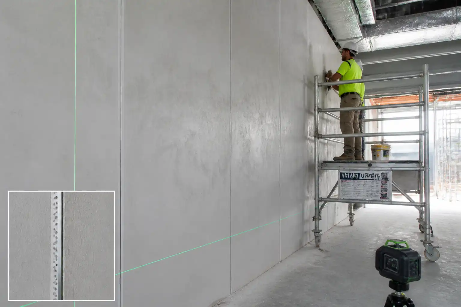

Inspection and Test Plan for Method Statement: Installation of Plaster Control Joints
AI-assisted inspection and test plan connected to a method statement, with PDF and Excel export.
More than a static template
Unlike a downloadable Word or PDF template, this ITP is an AI-assisted editable starting point directly connected to its method statement. Every inspection activity, hold point, and acceptance criterion is structured and ready to adapt to your project.
- AI-assisted customization — Tailor inspection activities and acceptance criteria to your specific project scope.
- Linked method statement — This ITP is connected to the corresponding method statement describing the work sequence.
- Multiple export formats — Download as a formatted PDF or editable Excel spreadsheet.
- Editable starting point, not a final document — Review and verify all content against your project specifications and standards before use.
What you can customize
When you save this ITP to your account, every inspection row becomes editable. You can add, remove, or modify:
- Inspection activity — Description of what is being inspected.
- Inspection type — Hold point (H), Witness point (W), Review (R), or Monitor (M).
- Responsibility — Contractor, subcontractor, engineer, or client.
- Frequency — How often the inspection occurs.
- Acceptance criteria — Referenced standard or specification requirement.
- Records — Forms, test reports, or checklists required as evidence.
Why this ITP is used
To ensure control joints are correctly located, installed, and inspected to prevent cracking and maintain performance.
Who uses this inspection and test plan
QA/QC engineers, site engineers, foremen, consultants, and third-party inspectors.
When this ITP is prepared and submitted
From pre-start through material receipt, installation, and final inspection before finishing works.
Who receives or approves this ITP
Consultant/Engineer and Client Representative for approvals and records.
Inspection scope
Covers layout verification, material compliance, lath discontinuity, fixing, alignment, sealant, and interface/rated details.
Typical hold, witness, and review points
HP-1 layout approval, HP-2 mock-up, HP-3 interface/rated details, HP-4 final inspection; witness checks during fixing and plaster application.
Typical inspection records
MIRs, IRs, checklists, measurement logs, photos, certificates, as-builts, NCR/CARs (if any).
Important approval note
This ITP is an AI-assisted editable starting point, not a pre-approved document. Before use on any project, all inspection activities, hold points, and acceptance criteria must be reviewed and approved by the relevant parties (superintendent, principal contractor, or client representative) in accordance with your contract and project quality plan.
Always verify acceptance criteria against your applicable drawings, specifications, and regulatory requirements. Hold points must be confirmed with the relevant authority before work proceeds past that point.
Inspection and test plan
| Activity | Inspection / Test | Acceptance Criteria | Responsibility | Record |
|---|---|---|---|---|
| Pre-start documentation | Verify approved MS/ITP, RA, permits in place | All approvals current; crew briefed | QA/QC Engineer | TBT record, approvals |
| Material receipt (MIR) | Inspect control joints, lath, fasteners, sealants per submittals | Conform to ASTM C1047/C1063 (as applicable); no damage/corrosion; correct sizes | QA/QC Engineer, Storekeeper | MIR, CoC, MDS |
| Layout verification (HP-1) | Survey/measure joint positions vs drawings | Locations correct; typical spacing within standards (e.g., exterior stucco panels ≤ ~13–15 m², max spacing 4.5–5.5 m) [Verify per project specifications] | Site Engineer, Consultant | IR with sketches/photos |
| Substrate condition check | Flatness/plumb, moisture, cleanliness | Meets project tolerances; moisture within manufacturer limits | QA/QC Engineer | Checklist, photos |
| Mock-up (HP-2, if specified) | Profile, reveal width, alignment, sealant (if any) | Approved aesthetics and compliance with spec | QA/QC Engineer, Consultant | IR approval, photos |
| Lath discontinuity at joints (if applicable) | Confirm lath break at joint centerline; tie to flanges | 6–10 mm break; tie wire spacing ≤150 mm; no bridging | QA/QC Engineer | Photos, checklist |
| Fixing of control joints | Check fastener type/spacing and corrosion protection | Fasteners ≤150 mm o.c. per flange; correct penetration; compatible metals | QA/QC Engineer | Checklist, photos |
| Alignment and width check | Measure plumb/level/straightness and reveal width | ±2 mm in 2 m; straightness ≤3 mm; width ±1 mm [Verify] | QA/QC Engineer | Measurement log |
| Interface/fire-acoustic details (HP-3) | Verify rated joint systems and continuity at interfaces | Installed per approved tested detail; labels/certs available | QA/QC Engineer, Consultant/Fire Specialist | IR, photos, certificates |
| Plaster application at joint edges | Visual check for no bridging; edge neatness | No plaster bridging across joint; edges true and clean | QA/QC Engineer | Photos, checklist |
| Sealant/backer rod (if required) | Check backer size, sealant depth, tooling; adhesion test if specified | Backer 25–50% oversize; depth ≈ half width; uniform finish; adhesion per ASTM C1521 if specified | QA/QC Engineer | Sealant log, test report |
| Final inspection prior to finishes (HP-4) | Comprehensive visual and dimensional inspection | All prior ITP items accepted; no damage/contamination; documentation complete | QA/QC Engineer, Consultant | Final IR, as-builts |
| As-built documentation | Update drawings with joint locations and details | Accurate and complete as-built records submitted | Site Engineer | As-built drawings |
This table is a read-only public reference. Download the PDF or Excel version, or customize this ITP to edit it for your project.
Frequently asked questions
Related method statement
This Inspection and Test Plan is associated with the Method Statement: Installation of Plaster Control Joints method statement, which describes the step-by-step construction sequence, resources, materials, equipment, safety controls, and environmental controls for this activity.
View the Method Statement: Installation of Plaster Control Joints method statement →