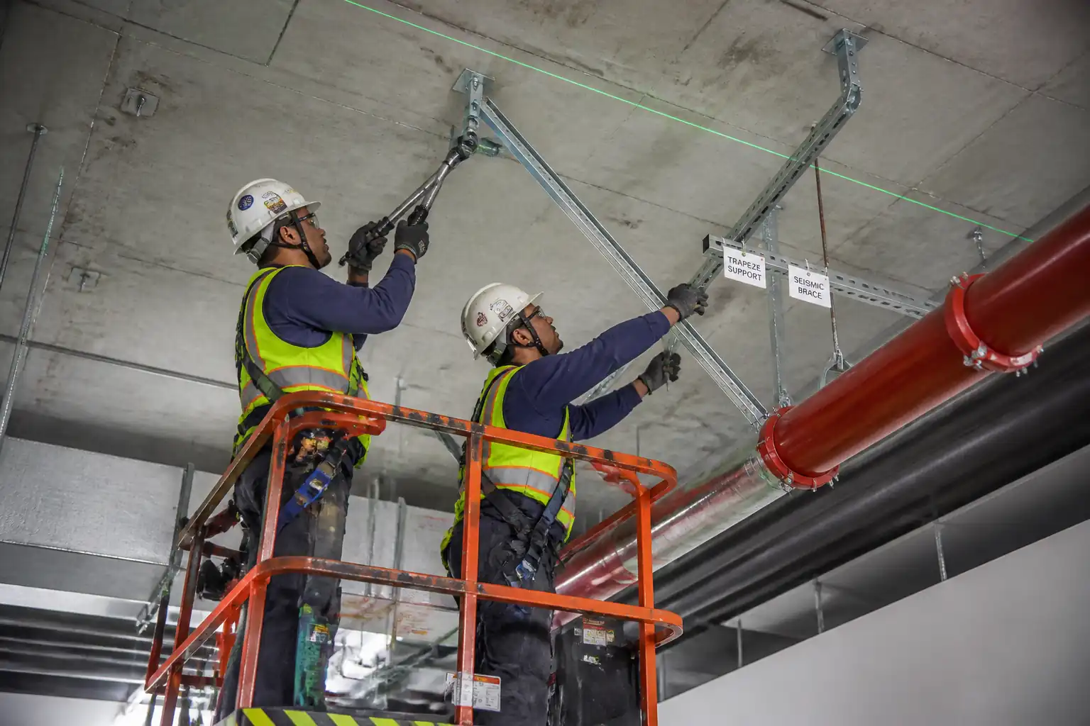

Method Statement: Installation of Pipe Supports, Hangers, Trapezes, and Seismic Restraints for Firefighting Piping – Method Statement
AI-assisted method statement with matching ITP, PDF download, and Excel export.
More than a static template
Unlike a downloadable Word or PDF template, this method statement is an AI-assisted editable starting point connected directly to a matching Inspection and Test Plan. Every section is structured, project-adaptable, and ready to export.
- AI-assisted drafting — Customize every section with AI for your specific project scope.
- Linked ITP — A matching inspection and test plan is generated alongside the method statement.
- Multiple export formats — Download as a formatted PDF or editable Excel spreadsheet.
- Editable starting point, not a final document — Review, verify, and adjust all content against your project requirements before use.
Static template vs. Quollnet workflow
| Feature | Static template | Quollnet |
|---|---|---|
| Project-specific content | Manual fill-in required | AI-assisted customization |
| Linked ITP | Separate document, no link | Matching ITP included |
| Export formats | Usually PDF only | PDF and Excel |
| Structured sections | Free-form layout | 13 standardized sections |
| Saved to your account | Local file only | Cloud-saved, reusable |
| Content accuracy | You verify everything | AI-assisted, you still verify |
| Cost | Often free but time-intensive | Free to customize and download |
What you can customize
When you save this method statement to your account, every section becomes editable. The following 13 sections are included:
- Scope — Defines the activity and its boundaries.
- References — Standards, specifications, and drawings.
- Responsibilities — Roles and accountabilities.
- Resources — Labour, plant, and equipment summary.
- Materials — Materials and compliance requirements.
- Equipment — Tools and equipment details.
- Prerequisites — Hold points and pre-conditions.
- Method sequence — Step-by-step construction sequence.
- Safety controls — HSE risk controls and PPE.
- Environmental controls — Environmental mitigation measures.
- QA/QC — Quality inspection and test requirements.
- ITP — Inspection and Test Plan table (has its own page).
- Attachments — Referenced drawings and documentation.
Why this method statement is used
This method statement is used to define and communicate the approved procedure for carrying out method statement: installation of pipe supports, hangers, trapezes, and seismic restraints for firefighting piping on site. It ensures the work is planned in advance, the correct resources and controls are in place, and all personnel understand responsibilities, sequence, quality requirements, and safety controls before work begins. It aligns site execution with the documented scope and acceptance expectations.
Who uses this method statement
This method statement is used by contractors, site supervisors, project engineers, QA/QC engineers, HSE officers, consultants, and client representatives. It serves as a shared reference for planning, execution, supervision, inspection, and approval of the activity on site.
When it is prepared and submitted
The method statement is prepared before the work activity starts and submitted as part of the pre-construction documentation package for review and approval.
Who reviews or approves it
The method statement is usually submitted to the client representative, consultant, resident engineer, or project management consultant for review and approval before the work commences.
Important approval note
This method statement is an AI-assisted editable starting point, not a pre-approved document. Before use on any project, all content must be reviewed and approved by the relevant parties (superintendent, principal contractor, or client representative) in accordance with your contract and project quality plan.
For example: if your specification requires a departure from a referenced standard, that departure must be documented and approved separately — this method statement will not capture that automatically. Always verify against your applicable drawings, specifications, and regulatory requirements.
Method statement content
Scope
Work Included
- Engineering, supply, installation, inspection, and testing of pipe supports and hangers for firefighting piping systems, including:
- Individual hangers (clevis, ring, split-ring), trapeze supports, and anchor points
- Seismic restraints (lateral and longitudinal bracing, sway bracing, riser restraints)
- Rod stiffeners and bracing for long hanger rods
- Load verification and support spacing compliance
- Corrosion protection of supports, rods, anchors, and fabricated trapezes
- Substrates: reinforced concrete, structural steel, and masonry (where permitted by design)
- Associated works: drilling/coring, post-installed anchors, torqueing/pull testing, welding (where specified), coating touch-up, and as-built documentation
Exclusions
- Underground/buried pipe supports unless specified
- Pipe fabrication, hydrostatic testing, and flushing (covered under separate method) except hanger adjustment during pipe placement
Key Hold/Witness Points
- Hold Point: Support spacing and locations inspection prior to bulk installation beyond first bay/zone
- Witness/Surveil: Anchor installation and testing, seismic brace installation, coating DFT measurements
Performance Requirements
- Supports to carry dead load of water-filled pipe, appurtenances, and seismic loads per approved design and NFPA 13/ASCE 7 [Verify per project specifications]
- Verticality, alignment, spacing, torque, embedment, and DFT to meet acceptance criteria in this method and ITP
- Seismic components UL/FM approved where required [Verify per project specifications]
References
| Document Type | Reference / Number | Revision | Notes |
|---|---|---|---|
| NFPA 13 | |||
| ASCE/SEI 7 | |||
| MSS SP-58, MSS SP-69, MSS SP-127 | |||
| ACI 318, ACI 355, ASTM E488/E488M | |||
| ICC-ES ESR / ETA | |||
| AWS D1.1 / D1.3 | |||
| ISO 1461; ASTM A123, A153, A780 | |||
| SSPC-PA 2; ISO 12944 | |||
| FMDS 2-0, 2-8 (as applicable) |
Responsibilities
| Role | Responsibility | Name / Party |
|---|---|---|
| PM | Ensure approved drawings, calculations, and materials are in place | Contractor |
| CM/SE | Ensure method compliance, set-out accuracy, and quality records | Contractor |
| QA/QC | Hold/witness point coordination; torque/pull test verification; DFT checks | Contractor |
| HSEO | Ensure controls for WAH, drilling, MEWP, chemicals; toolbox talks | Contractor |
| Surveyor/BIM | Provide coordinates and mark-ups; update as-builts | Contractor |
| Trades | Adhere to torque specs, welding WPS, coating systems, and alignment tolerances | Contractor |
| Specialist | Anchor testing, torque tool calibration, seismic brace commissioning (if required) | Independent/Manufacturer |
| Engineer | Review/approve hold points and key inspections; accept test records | Engineer |
Resources
| Resource Type | Description | Quantity | Remarks |
|---|---|---|---|
| Personnel | Project/Site Engineer, Foreman | 1–2 per crew [Verify] | Experienced with NFPA 13 installations |
| Personnel | Dedicated for inspections and tests | 1 | Holds torque/pull test competency |
| Personnel | Task risk management | 1 shared [Verify] | WAH, MEWP, chemical handling |
| Personnel | IPAF or equivalent certified | 1–2 | With spotter |
| Personnel | Install hangers, trapezes, braces | 2–6 per crew | Certified for rigging if lifting frames |
| Personnel | WPS/PQR qualified to AWS D1.1 or project spec | As needed | NDT if specified |
Materials
| Material | Specification / Grade | Quantity | Remarks |
|---|---|---|---|
| Carbon steel; SS in corrosive zones [Verify] | MSS SP-58/69; finish: HDG or zinc-plated [Verify] | ||
| ASTM A36/A307 or A193 B7 [Verify] | Diameter per design (typ. M10–M16) [Verify]; finish: HDG in wet areas | ||
| Structural steel to ASTM A36/EN 10025 [Verify] | HDG per ISO 1461 or powder coat [Verify] | ||
| Carbon steel 8.8/SS316 where required [Verify] | Follow ESR/ETA data for hole size, embedment, torque, cure | ||
| Steel; finish HDG | Capacity per design calc; manufacturer system compatible | ||
| Coating system ISO 12944 C2–C4 [Verify] | DFT 80–150 µm total [Verify]; repair per ASTM A780 |
Equipment
| Equipment | Capacity / Type | Quantity | Inspection Required |
|---|---|---|---|
| SDS-max; 10–32 mm bits [Verify] | |||
| GPR/ferroscan | |||
| 10–300 Nm range [Verify] | |||
| Up to required proof loads | |||
| IPAF compliant | |||
| 0.5–2 t WLL | |||
| Magnetic/electronic DFT gauges |
Prerequisites
Documentation and Approvals
- Approved IFC/shop drawings, hanger schedules, seismic bracing layouts, and calculations signed by a qualified engineer [Verify per project specifications]
- Approved materials: MIR with MTCs/CoC for hangers, rods, anchors, coatings; UL/FM listings as required
- Method Statement and ITP approved by Engineer
Permits and Coordination
- Permit to Work for drilling into structural concrete and for Working at Height [Verify per project HSE plan and local regulations]
- Structural approval for drilling near PT tendons/rebar; marked PT tendon/embedded service maps
- Coordination with other trades (MEP/BIM) to avoid clashes and maintain clearances
Equipment Readiness
- Calibrated torque wrenches and pull-test equipment with valid certificates
- MEWPs inspected and tagged; operators certified
Site Conditions
- Access and lighting available; exclusion zones planned
- Substrate condition verified: sound concrete/steel; no spalls or delamination at anchor locations
Hold Points Communicated
- Hold Point: Support spacing and locations inspection planned after layout/marking and before bulk installation beyond first bay/zone
Toolbox Talk
- Task-specific briefing covering WAH, drilling hazards, silica dust, chemical anchors, lifting, and exclusion zones
Method Sequence
| Step | Activity | Description | Responsibility | Inspection / Hold Point |
|---|---|---|---|---|
| 1 | Review and Set-out | Review approved drawings and calculations; walkdown area; establish control lines/elevations using laser; mark proposed support locations on soffits/beams with paint/markers; tag by unique IDs | Site Engineer / Surveyor | Internal check of layout vs drawings |
| 2 | Substrate Scanning and Permit Confirmation | Scan anchor points with GPR/ferroscan to avoid PT tendons, rebar, and embedded services; update marks as needed; obtain drill permit sign-off | HSE / Site Engineer | Permit review and scan results |
| 3 | Hold Point – Support Spacing and Locations Inspection | Before bulk installation, present marked layout showing hanger spacing by pipe size/route, trapeze positions, and anchor types to Engineer for verification | QA/QC Engineer | Engineer/Consultant verification |
| 4 | Drilling and Hole Preparation | Drill holes to required diameter and depth; use dust extraction; for adhesive anchors, follow manufacturer hole cleaning: blow–brush–blow cycles; verify hole depth with gauge | Installer | Supervisor verification of hole depth/cleanliness |
| 5 | Anchor Installation – Mechanical | Install mechanical anchors (wedge/undercut) to required embedment; apply installation torque using calibrated wrench; mark bolt head after torque | Installer | QA/QC spot checks |
| 6 | Anchor Installation – Adhesive (if specified) | Inject adhesive from bottom of hole; insert threaded rod with twist motion to design embedment; maintain gel/curing time before loading per TDS; temperature logged | Installer | QA/QC review of batch/expiry; curing time log |
| 7 | Anchor Proof Testing | Perform field proof tests on representative anchors using hydraulic tester | QA/QC / Third-Party | Engineer witness (as specified) |
| 8 | Fabricate/Assemble Trapezes | Cut channels/angles; deburr; assemble with bolts or welds per WPS; trial-fit on ground where possible; apply shop primer/galvanizing repair to cut edges | Shop/Installer | Dimensional check; WPS adherence |
| 9 | Install Hangers/Trapezes | Fix hanger rods/trapeze to anchors or beams; use locknuts; ensure rod verticality; set elevations with laser; tag supports with IDs | Installer | Supervisor/QA visual check |
| 10 | Pipe Placement and Adjustment | Lift pipe onto hangers/trapezes; install clamps; adjust to final line/grade; tighten nuts to snug-plus as per MSS SP-69 | Pipefitters/Riggers | Supervisor check |
| 11 | Install Seismic Restraints | Install lateral/longitudinal braces, sway bracing, and riser restraints per approved seismic layout; torque bolts; install listed clamps | Installer | QA/QC check; Engineer witness as specified |
| 12 | Rod Stiffeners / Lateral Bracing of Long Rods | Install stiffener channels/angles or cross-bracing to long hanger rods where specified; secure with clamps/bolts | Installer | QA/QC verification |
| 13 | Corrosion Protection and Touch-up | Apply coating/galvanizing repair to cut edges, welds, and damaged areas; measure DFT; ensure full coverage | Coating Applicator | QA/QC DFT checks |
| 14 | Final QA/QC and As-built | Comprehensive inspection of supports, anchors, braces; confirm tags; compile torque/pull/DFT records; update as-builts | QA/QC Engineer | Engineer final walkdown |
Health, Safety, and Environment (HSE) – Safety Controls
Task-Specific Hazards and Controls
1) Working at Height (MEWPs/Scaffolds)
- Hazard: Falls from height; tip-over
- Likely consequence: Major injury/fatality
- Engineering/procedural control: Use certified MEWPs with pre-use checks; set outriggers on level surfaces; maintain exclusion zone; wear full body harness with short lanyard in boom lifts; do not overreach; keep platform floor clear; follow rescue plan
- Required PPE: Helmet with chinstrap, fall arrest harness (MEWPs), safety boots, gloves, eye protection
- Collective measure: Edge protection where feasible; barricades and signage below
- Inspection/permit/supervision: WAH permit; MEWP inspection tags; competent operator (IPAF or equivalent); supervisor spot checks [Verify per project HSE plan and local regulations]
2) Drilling into Concrete Near PT/Rebar/Utilities
- Hazard: Striking PT tendon/electrical/concealed services
- Likely consequence: Structural failure, electrocution, flooding
- Engineering/procedural control: Mandatory GPR/ferroscan and service clearance; drilling permit; stop-work if resistance change indicates steel; use drill stops; avoid redlined no-drill zones
- Required PPE: Dielectric gloves when near electrical, eye/face shield, hearing protection, dust mask (P2/P3)
- Collective measure: Tool lanyards; exclusion zone beneath workface
- Inspection/permit/supervision: Drilling permit; scan record; supervision during first hole each zone
3) Falling Objects/Loose Tools
- Hazard: Materials/tools falling from height
- Likely consequence: Head injury/struck-by
- Engineering/procedural control: Use tool lanyards; net or toe-boards on platforms; secondary retention for chain blocks; store small parts in closed pouches
- Required PPE: Hard hat with chinstrap, safety boots, safety glasses
- Collective measure: Barricaded drop zones; spotter
- Inspection/permit/supervision: Daily checks of lanyards and rigging; enforce exclusion zones
4) Manual Handling and Pinch Points
- Hazard: Musculoskeletal injury; crushed fingers during lifting/aligning trapezes/pipes
- Likely consequence: Strains, fractures
- Engineering/procedural control: Team lifts; use chain blocks; plan lift points; keep hands clear; use taglines
- Required PPE: Impact gloves, boots
- Collective measure: Lift plans for heavy items; mechanical aids
- Inspection/permit/supervision: Pre-task brief and LMRA; rigger in charge
5) Noise and Vibration from Drilling
- Hazard: Hearing damage; HAVS
- Likely consequence: Permanent hearing loss; hand-arm vibration injury
- Engineering/procedural control: Low-vibration tools; limit trigger time; rotate tasks; use damped bits
- Required PPE: Class 3 hearing protection
- Collective measure: Noise barriers/time restrictions where required
- Inspection/permit/supervision: Monitor noise levels; maintain HAVS logs [Verify per project HSE plan]
6) Dust and Silica Exposure
- Hazard: Respirable crystalline silica from drilling
- Likely consequence: Respiratory disease
- Engineering/procedural control: On-tool extraction with HEPA; wet methods where safe; housekeeping with HEPA vacuums (no dry sweeping)
- Required PPE: P2/P3 respirators; eye protection
- Collective measure: Isolation of fire alarm heads; local ventilation
- Inspection/permit/supervision: Air monitoring if required; housekeeping inspections
7) Chemical Anchors/Coatings (VOC, Skin/Eye Irritation)
- Hazard: Chemical exposure; sensitization
- Likely consequence: Burns, respiratory irritation
- Engineering/procedural control: Review SDS; use correct mixing nozzles; provide ventilation; spill kits; avoid skin contact
- Required PPE: Chemical-resistant gloves, goggles/face shield, coveralls
- Collective measure: Designated mixing/dispensing area with drip trays
- Inspection/permit/supervision: COSHH assessment; SDS on site; first-aid eyewash
8) Welding/Hot Work (if applicable)
- Hazard: Fire, burns, fumes
- Likely consequence: Fire, injury
- Engineering/procedural control: Hot Work Permit; fire watch; shields; local extraction
- Required PPE: Welding hood, FR clothing, gloves
- Collective measure: Fire blankets; extinguishers at point of work
- Inspection/permit/supervision: Gas monitoring if confined; permit closeout
9) Lifting Operations with Chain Blocks/Hoists
- Hazard: Load drop, overloading
- Likely consequence: Crush injuries
- Engineering/procedural control: Use certified gear; within WLL; inspect slings; controlled lift plan
- Required PPE: Helmets, gloves, boots
- Collective measure: Exclusion zones; taglines
- Inspection/permit/supervision: Lifting plan/permit where required; appointed person supervision
10) Energized Systems in Vicinity
- Hazard: Contact with live electrical or active sprinklers
- Likely consequence: Shock, unintended discharge
- Engineering/procedural control: Lock-out/tag-out (LOTO) for affected systems; isolate/notify
- Required PPE: Electrical-rated gloves (as needed), eye protection
- Collective measure: Signage and barriers
- Inspection/permit/supervision: LOTO records; supervisor authorization
Note: All controls subject to verification per project HSE plan and local regulations.
Environmental Controls
Environmental Aspects and Controls
- Dust and Debris: Use on-tool HEPA extraction; wet coring where safe; cover adjacent finishes; collect slurry in trays and dispose as per waste plan
- Noise: Schedule high-noise drilling during permitted hours; use acoustic barriers if required; notify stakeholders
- Waste Management: Segregate metal offcuts, spent cartridges/nozzles, used rags, and empty cans; dispose per MSDS and local regulations; maintain waste logs
- Spills/Leaks: Store chemicals in bunded trays; keep spill kits; train crew in spill response; report and clean immediately
- Coating Overspray/Drips: Mask adjacent surfaces; use drop cloths; apply by brush/roller where practical
- Energy/Carbon: Use electric MEWPs where feasible; minimize idle times
- Fire Alarm Management: Isolate/cover detectors during dusty works; re-instate and function check after works
- Environmental Monitoring: Record noise/dust complaints and corrective actions [Verify per project environmental plan]
Quality Assurance and Quality Control (QA/QC)
Pre-Installation
- Verify approvals: Drawings, seismic calcs, material submittals, WPS, MIRs
- Calibration: Torque wrenches and pull-test rigs within validity; keep certificates accessible
- Mock-up (if specified): Install sample bay for approval prior to bulk works
Load Verification
- Determine service load per support: W = (pipe weight empty + water weight + valves/fittings + allowances) per meter × tributary length; include seismic vertical/uplift where required
- Check anchor/rod/member allowable capacities ≥ factored loads with appropriate safety factors per NFPA 13/ASCE 7/manufacturer [Verify per project specifications]
- Long rod stability: Verify buckling capacity with stiffeners/bracing as detailed; FoS ≥2.0 [Verify]
Tolerances and Workmanship
- Hanger rod verticality ≤2° from plumb
- Pipe elevation ±5 mm; alignment ±10 mm
- Trapeze deflection under dead load ≤L/360 [Verify]
- Anchor embedment −0/+5 mm; torque within −0/+10% of specified value
- Support spacing per NFPA 13 tables and approved drawings [Verify exact values]
Inspections and Tests
- Hold Point: Support spacing and location inspection prior to bulk install
- Torque checks: ≥10% per size/type/shift [Verify]
- Anchor proof tests: ≥2% (min 5) per size/type/substrate at 1.25× service tension; no pullout; displacement ≤1 mm [Verify]
- Coating DFT: SSPC-PA 2; achieve 80–150 µm (or project-specified) total system DFT [Verify]
Documentation
- ITRs for layout, anchors, hangers/trapezes, seismic braces, rod stiffeners, coating
- Logs: Torque, pull tests, adhesive batch/cure, DFT, calibration
- Nonconformance: Record NCRs, corrective actions, re-inspection
- As-builts: Update hanger IDs, brace locations, anchor types, and elevations
Acceptance
- All inspections pass; no visible defects; all records submitted and approved by Engineer; UL/FM compliance where required [Verify]
Attachments
- Sample calculation sheet for support loads and seismic bracing (signed)
- Typical hanger and trapeze detail drawings with IDs
- Seismic bracing schedule and manufacturer datasheets
- Anchor ESR/ETA and TDS; torque table; hole cleaning procedures
- Torque log template (ITR-02)
- Adhesive anchor installation/cure log (ITR-02A)
- Anchor pull test report template (PTR-01)
- Hanger/trapeze installation checklist (ITR-03)
- Seismic brace inspection checklist (ITR-04)
- Rod stiffener checklist (ITR-05)
- Coating inspection and DFT log (CIR-01)
- MEWP daily inspection checklist
- Permit to drill and GPR/ferroscan log form
- NCR and RFI templates
This content is a read-only public reference. Download or customize to get an editable version.
ITP preview
The first inspection activities from the linked ITP for Method Statement: Installation of Pipe Supports, Hangers, Trapezes, and Seismic Restraints for Firefighting Piping:
| Activity | Inspection / Test | Acceptance Criteria | Responsibility | Record |
|---|---|---|---|---|
| Material receiving and verification | Check MIR, MTC/CoC, listings; coating finish | Materials match approved submittals; no damage/corrosion; listings as specified | QA/QC; Storekeeper | MIR; receiving inspection report |
| Pre-install layout and marking | Verify support spacing and locations against drawings/NFPA 13 | Layout consistent with approved drawings and NFPA 13 tables [Verify exact values] | Site Engineer; QA/QC; Engineer/Consultant | ITR-01 layout inspection |
| Substrate scanning and permit to drill | GPR/ferroscan records | No conflicts with PT tendons/services; permit approved | HSE; Site Engineer; Engineer (as required) | Permit to drill; scan log |
Showing 3 of 13 inspection activities. View full ITP →
Related Inspection and Test Plan
An Inspection and Test Plan (ITP) is available for Method Statement: Installation of Pipe Supports, Hangers, Trapezes, and Seismic Restraints for Firefighting Piping. The ITP defines the inspection activities, acceptance criteria, hold and witness points, responsible parties, and records required to verify the work described in this method statement.
View the Method Statement: Installation of Pipe Supports, Hangers, Trapezes, and Seismic Restraints for Firefighting Piping ITP →