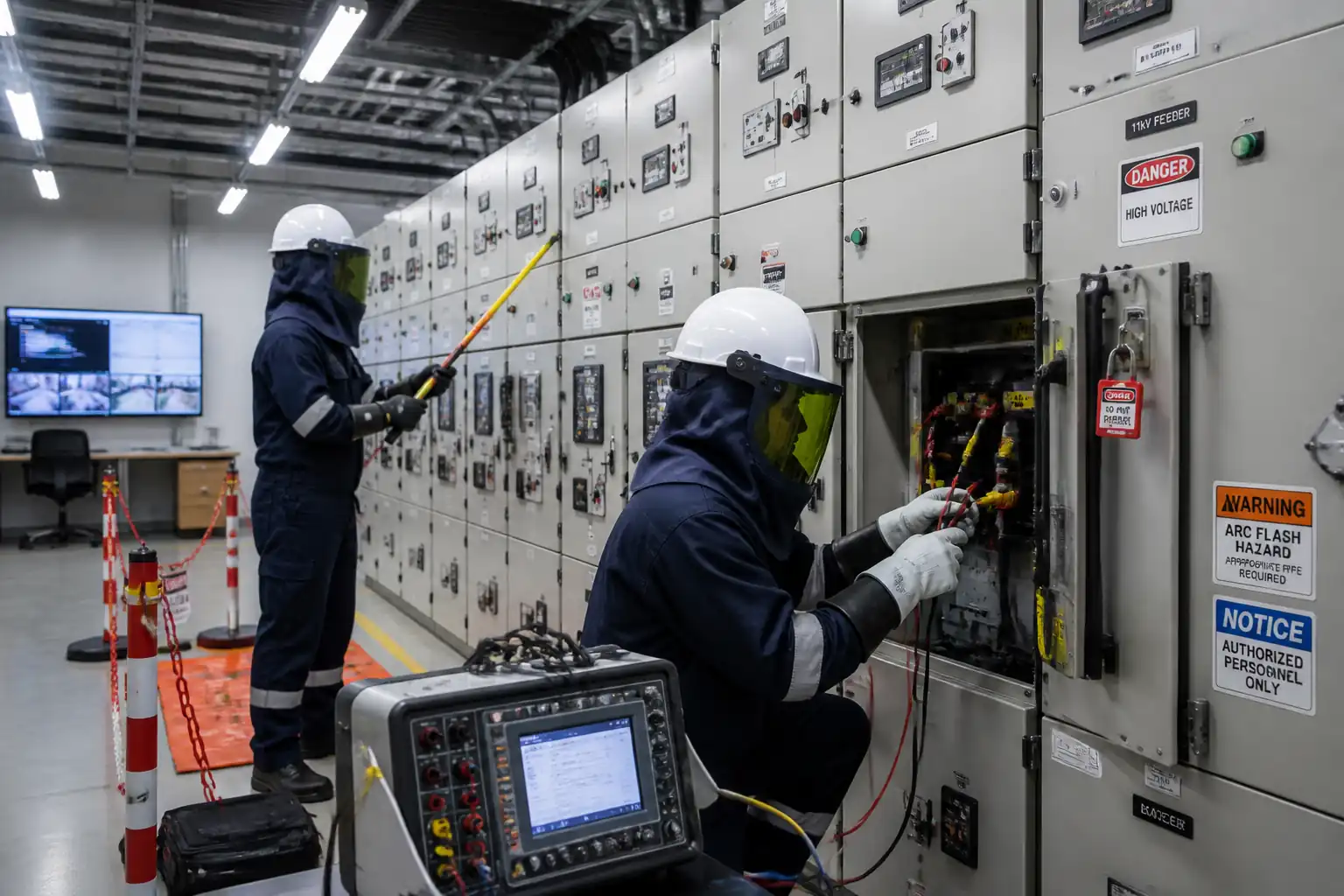

Method Statement: HV Switching and Commissioning of RMU/Switchgear – Method Statement
AI-assisted method statement with matching ITP, PDF download, and Excel export.
More than a static template
Unlike a downloadable Word or PDF template, this method statement is an AI-assisted editable starting point connected directly to a matching Inspection and Test Plan. Every section is structured, project-adaptable, and ready to export.
- AI-assisted drafting — Customize every section with AI for your specific project scope.
- Linked ITP — A matching inspection and test plan is generated alongside the method statement.
- Multiple export formats — Download as a formatted PDF or editable Excel spreadsheet.
- Editable starting point, not a final document — Review, verify, and adjust all content against your project requirements before use.
Static template vs. Quollnet workflow
| Feature | Static template | Quollnet |
|---|---|---|
| Project-specific content | Manual fill-in required | AI-assisted customization |
| Linked ITP | Separate document, no link | Matching ITP included |
| Export formats | Usually PDF only | PDF and Excel |
| Structured sections | Free-form layout | 13 standardized sections |
| Saved to your account | Local file only | Cloud-saved, reusable |
| Content accuracy | You verify everything | AI-assisted, you still verify |
| Cost | Often free but time-intensive | Free to customize and download |
What you can customize
When you save this method statement to your account, every section becomes editable. The following 13 sections are included:
- Scope — Defines the activity and its boundaries.
- References — Standards, specifications, and drawings.
- Responsibilities — Roles and accountabilities.
- Resources — Labour, plant, and equipment summary.
- Materials — Materials and compliance requirements.
- Equipment — Tools and equipment details.
- Prerequisites — Hold points and pre-conditions.
- Method sequence — Step-by-step construction sequence.
- Safety controls — HSE risk controls and PPE.
- Environmental controls — Environmental mitigation measures.
- QA/QC — Quality inspection and test requirements.
- ITP — Inspection and Test Plan table (has its own page).
- Attachments — Referenced drawings and documentation.
Why this method statement is used
This method statement is used to define and communicate the approved procedure for carrying out method statement: hv switching and commissioning of rmu/switchgear on site. It ensures the work is planned in advance, the correct resources and controls are in place, and all personnel understand responsibilities, sequence, quality requirements, and safety controls before work begins. It aligns site execution with the documented scope and acceptance expectations.
Who uses this method statement
This method statement is used by contractors, site supervisors, project engineers, QA/QC engineers, HSE officers, consultants, and client representatives. It serves as a shared reference for planning, execution, supervision, inspection, and approval of the activity on site.
When it is prepared and submitted
The method statement is prepared before the work activity starts and submitted as part of the pre-construction documentation package for review and approval.
Who reviews or approves it
The method statement is usually submitted to the client representative, consultant, resident engineer, or project management consultant for review and approval before the work commences.
Important approval note
This method statement is an AI-assisted editable starting point, not a pre-approved document. Before use on any project, all content must be reviewed and approved by the relevant parties (superintendent, principal contractor, or client representative) in accordance with your contract and project quality plan.
For example: if your specification requires a departure from a referenced standard, that departure must be documented and approved separately — this method statement will not capture that automatically. Always verify against your applicable drawings, specifications, and regulatory requirements.
Method statement content
Scope
Overview
This method statement covers pre-commissioning, commissioning, testing, and energisation of medium-voltage (MV) Ring Main Units (RMU) and metal-enclosed switchgear (typically 11–36 kV), including:
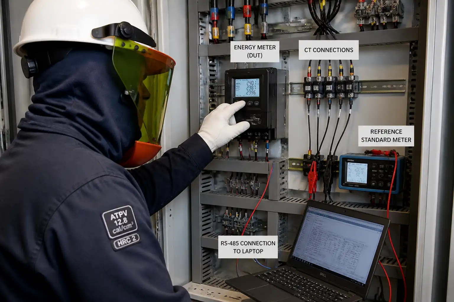
- Visual inspection, mechanical checks, torqueing, gas pressure verification (for SF6 RMUs)
- Functional checks of interlocks (mechanical/electrical/key interlocks, earthing switch interlocks)
- Insulation resistance and contact resistance testing
- Protection relays configuration, secondary injection testing, and logic verification
- CT/VT polarity and ratio verification
- Primary injection testing for protection pick-up and timing
- SCADA/RTU point-to-point testing and intertripping tests
- Phasing checks and authority-coordinated energisation with strict safety Hold Points
- Post-energisation monitoring and documentation handover
Works shall be executed by competent, HV-authorised personnel under an approved switching program and Permit-to-Work system.
References
| Document Type | Reference / Number | Revision | Notes |
|---|---|---|---|
| IEC 62271-200: High-voltage switchgear and controlgear – AC metal-enclosed switchgear and controlgear for rated voltages above 1 kV and up to and including 52 kV | |||
| IEC 62271-100/102/105: HV circuit-breakers, disconnectors/earthing switches, and switch-fuse combinations (as applicable) | |||
| IEC 61869 (series): Instrument transformers (CTs/VTs) – accuracy classes and testing | |||
| IEC 60255 (series): Measuring relays and protection equipment – functional and testing requirements | |||
| IEC 60529: Degrees of protection (IP code) – enclosure integrity checks (visual) | |||
| IEC 60947-3 (as relevant for load-break switches in RMUs) | |||
| IEC 61243-1/-5: Live working – voltage detectors / capacitive voltage indicators (VDS) | |||
| BS EN 50110-1: Operation of electrical installations – safety procedures for HV switching | |||
| NFPA 70E / IEC 61482: Arc-flash PPE selection and live working arc protection [Verify per project HSE plan and local regulations] | |||
| ISO/IEC 17025: Calibration of test equipment; ISO 9001, ISO 14001, ISO 45001 management systems | |||
| Manufacturer O&M manuals and project specifications (switchgear, RMU, relays, SCADA) – governing on-site tests and limits | Project specifications take precedence; verify any numerical limits |
Responsibilities
| Role | Responsibility | Name / Party |
|---|---|---|
| Commissioning Manager | Overall control | Contractor |
| HV Authorized Person (AP) / Switching Engineer | Electrical safety and switching | Contractor |
| Protection & Control Engineer | Protection settings & tests | Contractor |
| SCADA/Telecom Engineer | SCADA/RTU integration | Contractor |
| QA/QC Engineer | Quality assurance | Contractor |
| HSE Officer | HSE oversight | Contractor |
| Manufacturer’s Representative | OEM technical support | Supplier/OEM |
| Engineer/Consultant | Design compliance & witnessing | Engineer |
| Utility/Authority Representative | System operation approval | Authority |
Resources
| Resource Type | Description | Quantity | Remarks |
|---|---|---|---|
| Personnel | Commissioning Manager | 1 | |
| Personnel | HV Authorized Person (AP) / Switching Engineer | 1–2 | |
| Personnel | Protection & Control Engineers/Technicians | 2–4 | |
| Personnel | SCADA/RTU Engineer | 1 | |
| Personnel | QA/QC Engineer | 1 | |
| Personnel | HSE Officer | 1 |
Materials
| Material | Specification / Grade | Quantity | Remarks |
|---|---|---|---|
| Interlock keys and cylinders | OEM specified code set [Verify] | As required | |
| Approved terminations, lugs, ferrules | Copper tinned, to IEC 61238-1 | As required | |
| LOTO devices and tags | Durable, UV resistant, unique ID | Set per panel | |
| SF6 gas and fittings | IEC 60376 grade; leak-free couplings [Verify] | As required | |
| Engraved labels and mimic diagrams | Heat-resistant; per project ID standard | As required |
Equipment
| Equipment | Capacity / Type | Quantity | Inspection Required |
|---|---|---|---|
| Primary injection set | Up to 5–10 kA, 0–10 V; accuracy ≤1% [Verify] | 1 | Calibration cert ≤12 months [Verify] |
| Secondary injection relay test set | 3ϕ voltage/current outputs; accuracy ≤0.1% | 1 | Calibration cert ≤12 months [Verify] |
| Digital micro-ohmmeter | 100 A DC; resolution 0.1 µΩ | 1 | Calibration cert valid |
| Insulation resistance tester | 5 kV DC; PI/DAR capability | 1 | Calibration cert valid |
| Phasing sticks / voltage detectors | Rated 11–36 kV; IEC 61243 compliant | 1 set | Daily function check |
| Mobile earthing equipment | Thermal rating per system fault level | As required | Visual check; test cert valid |
| SF6 handling cart/leak detector | Recovery/vacuum; leak detection ≤1×10⁻⁶ mbar·l/s | 1 | Operator certified [Verify] |
| Calibrated torque wrenches | Up to OEM torque values | Set | Calibration cert valid |
| Thermal imaging camera | NETD ≤50 mK; emissivity adj. | 1 | Calibration cert valid |
| Engineering laptop/workstation | Time sync (SNTP/IRIG-B) capable | 1 | Software versions approved |
Prerequisites
- Approved drawings: single line diagrams (SLD), protection coordination study, wiring diagrams, interlock/key exchange scheme, SCADA I/O lists.
- Approved ITP and risk assessments/method statement (RAMS). Toolbox Talk completed and signed.
- Permits: HV Permit-to-Work, Sanction-for-Test, LOTO in place. Access control established.
- Equipment condition: Delivery inspections closed; damage/nonconformities resolved. OEM manuals available.
- Test equipment: Calibrations in date; function checks recorded.
- DC supply available and stable (e.g., 110/220 VDC) with battery charger functional.
- Outage/energisation plan approved by Utility/Authority and Client, including Hold/Witness points and communications protocol.
- Earthing system complete and tested (continuity and resistance within project limits [Verify per project specifications]).
- Environmental controls prepared: SF6 handling plan (if applicable), spill kits, waste receptacles.
- Emergency response: Arc-flash boundaries marked, rescue kit and first aid ready, emergency contacts posted.
Method Sequence
| Step | Activity | Description | Responsibility | Inspection / Hold Point |
|---|---|---|---|---|
| 1 | Pre-start briefing and permit issue | Conduct Toolbox Talk; confirm scope, roles, hazards, arc-flash boundaries. Issue HV Permit-to-Work and Sanction-for-Test. Establish LOTO. | HV AP / HSE | Permit review |
| 2 | Visual and mechanical inspection | Verify panel ratings/nameplates, IP integrity, space heaters, cable terminations, torque check per OEM, cleanliness, mechanism lubrication. | Commissioning Team | Checklist + torque log |
| 3 | Gas pressure (SF6 RMU) | Record gas pressure at reference temperature; top-up/recover as needed; leak check with detector/soap test. | OEM Rep / Commissioning | Gauge reading + leak test |
| 4 | Earthing and bonding verification | Verify frame-to-earth continuity and earthing bar connections; inspect mobile earthing leads. | Commissioning Team | Continuity test |
| 5 | Insulation resistance (IR) tests | Isolate sensitive equipment; test main circuits at 5 kV DC; control/secondary circuits at 500–1000 V DC as applicable. | Test Technicians | Megger readings |
| 6 | Contact resistance | Measure main contact resistance per pole across CB/isolator using 100 A DC micro-ohmmeter. | Test Technicians | Ductor readings |
| 7 | CT/VT polarity and ratio | Check polarity marks (P1/P2, S1/S2); perform ratio check (secondary injection for VT, primary or burdened secondary for CT). | Protection Engineer | Test results |
| 8 | Functional interlock checks | Verify mechanical/electrical/key interlocks: earthing switch cannot close when CB closed; cable doors open only when earthed; key exchange logic. | Commissioning + OEM | Functional demonstration |
| 9 | DC supply and trip circuit supervision | Verify charger output and battery health; check trip circuit supervision alarms, local/remote E-Stop, spring charge motors. | P&C Engineer | Measurements + alarms |
| 10 | Relay settings upload and verification | Load approved settings; lock configuration; record checksum/version; enable password protection. | Protection Engineer | Settings file review |
| 11 | Secondary injection tests | Functionally test O/C, E/F, SEF, directional, intertrips, autoreclose (if any), and logic (trip/close, block, alarms). | Protection Engineer | Witness test |
| 12 | Primary injection tests | Inject primary current through CT circuit to prove ratio, polarity, wiring integrity, and end-to-end tripping. | Protection + Test Team | Witness test |
| 13 | SCADA/RTU and SOE checks | Point-to-point verification: status, analogues, commands, interlocks, time sync, comms fail alarms. | SCADA Engineer | I/O sheets |
| 14 | Phasing and phase rotation check | With Utility, confirm phase identity/sequence at open point using phasing sticks; ensure no cross-phasing before paralleling. | HV AP + Utility | Witness phasing |
| 15 | Final pre-energisation review | Close all punch lists; verify interlocks and settings locked; confirm removal of temporary earths; clear work area. | Commissioning Manager | Walkdown |
| 16 | Authority switching and energisation | Execute approved switching program with Utility; remove LOTO as authorised; energise per sequence; record times/SOE. | Utility + HV AP | Witness by Client/Engineer |
| 17 | Post-energisation monitoring | Measure load currents/voltages; thermal scan after stabilization; verify alarms; re-check gas pressure (if applicable). | Commissioning Team | Thermal/operational check |
| 18 | Handover and documentation | Compile as-built drawings, settings, test reports, training records, O&M manuals; obtain approvals. | QA/QC + Commissioning | Document review |
Health and Safety Controls
Hazard controls (task-specific)
1) Hazard: Arc-flash and HV electric shock
- Likely consequence: Severe burns, fatality
- Engineering/procedural control: Strict LOTO and Sanction-for-Test; establish arc-flash boundary per study; remote operation where possible; use properly rated phasing sticks; prove dead and apply portable earths before any contact
- Required PPE: Arc-rated suit (CAT per study), HV-rated gloves (IEC 60903) with leather protectors, face shield/hood, hearing protection, safety footwear
- Collective preventive measure: Physical barriers and arc-flash boundary tape; interlocked doors; keep non-essential persons outside controlled area
- Inspection/permit/supervision: HV Permit-to-Work; AP presence during switching; equipment visual check; daily tool inspection; [Verify per project HSE plan and local regulations]
2) Hazard: Unexpected energisation/backfeed (incl. induced voltages)
- Likely consequence: Electric shock, arc-flash
- Engineering/procedural control: System isolation at all sources; check for backfeeds; apply and tag portable earths at all points; use voltage detector to prove dead; maintain equipotential bonding
- Required PPE: Arc-rated clothing, HV gloves, face shield
- Collective preventive measure: Key control and lockboxes; controlled access
- Inspection/permit/supervision: LOTO register; AP verification and sign-off
3) Hazard: Stored mechanical energy (spring-charged mechanisms)
- Likely consequence: Crush/impact injuries
- Engineering/procedural control: Discharge springs per OEM before maintenance; use interlocks; handle mechanisms with tools only
- Required PPE: Cut-resistant gloves, safety glasses
- Collective preventive measure: Clear signage and barriers
- Inspection/permit/supervision: OEM procedures available; supervisor oversight
4) Hazard: SF6 exposure/leak (asphyxiation, environmental impact)
- Likely consequence: Respiratory issues, environmental harm
- Engineering/procedural control: Use certified SF6 handling cart; leak test; provide ventilation; prohibit venting to atmosphere
- Required PPE: Nitrile gloves, safety glasses; respirator if required [Verify]
- Collective preventive measure: Local exhaust/ventilation, gas detectors if indoors
- Inspection/permit/supervision: Trained/certified operator; gas logs; recovery certificates
5) Hazard: Manual handling of heavy test sets
- Likely consequence: Musculoskeletal injuries
- Engineering/procedural control: Use trolleys/lifters; team lifts; plan movement path
- Required PPE: Safety shoes, back support (as needed), gloves
- Collective preventive measure: Keep routes clear; ramp/edge protection
- Inspection/permit/supervision: Manual handling assessment; supervisor brief
6) Hazard: Trip hazards from test leads and open panels
- Likely consequence: Slips, trips, falls
- Engineering/procedural control: Cable management, mats, cover unused openings; maintain housekeeping
- Required PPE: Safety footwear
- Collective preventive measure: Barrier off test area; signage
- Inspection/permit/supervision: Housekeeping inspections; HSE walkdowns
7) Hazard: Battery/DC systems (chemical/electrical)
- Likely consequence: Burns, eye injury, shock
- Engineering/procedural control: Insulated tools; correct polarity; charger isolation before work
- Required PPE: Eye protection, acid-resistant gloves
- Collective preventive measure: Spill kit and eyewash nearby
- Inspection/permit/supervision: Battery maintenance records; permits as required
Emergency preparedness: First-aid kit and ARC burn kit available; rescue hook; clear egress routes; emergency numbers displayed.
Environmental Controls
- SF6 management: No venting; recover/recycle using certified equipment; maintain gas logs and leak records; report any leak per environmental plan.
- Waste management: Collect used wipes, packaging, replaced fuses/parts, and test consumables; segregate e-waste; dispose via licensed contractor.
- Spill prevention: Keep spill kits at substation; drip trays for SF6 cart or oil-filled auxiliaries (if any).
- Noise and working hours: Schedule primary injection and switching within permitted hours; use hearing protection if >85 dB.
- Energy efficiency: De-energise test equipment when idle; minimize idling of generators (if used).
- Dust/cleaning: Use lint-free cloths; avoid compressed air that may spread contaminants.
- Documentation: Environmental inspections and waste transfer notes retained. [Verify per project HSE plan and local regulations]
Quality Assurance / Quality Control
- Calibrations: All instruments with valid ISO/IEC 17025 traceable calibration certificates (≤12 months unless otherwise specified). Function checks recorded daily.
- Identification: All panels, circuits, CT/VT cores, and interlock keys labelled as per approved drawings prior to testing.
- Testing tolerances and metrics:
- IR tests: MV ≥100 MΩ at 5 kV/1 min; control ≥5 MΩ at 500–1000 V [Verify per project]. Temperature-correct readings where required.
- Contact resistance: Within OEM limits; typical ≤100 µΩ/pole and phase balance within 20% [Verify].
- Protection timing/accuracy: Pickup ±5%; time ±10% or ±30 ms, whichever greater [Verify per relay].
- CT/VT accuracy: Within IEC 61869 class; polarity correct.
- SCADA: 100% point accuracy and command interlocking proven; time sync within ±1 s [Verify].
- Documentation control: Test sheets signed by tester and reviewer; Witness/Hold points countersigned by Consultant/Utility. Deviations logged via NCR and approved disposition.
- As-built deliverables: Approved settings files (checksum), event recorder screenshots, SOE logs, wiring markups, gas logs (if SF6), torque logs, O&M manuals, training records.
- Change management: Any setting or wiring change post-approval requires updated coordination study or formal TQ/approval before implementation.
Attachments
- Sample: HV Switching Program Template
- Sample: LOTO Register and Tag Log
- Sample: Interlock Verification Checklist
- Sample: Relay Settings Approval Sheet (with checksum)
- Sample: Primary/Secondary Injection Test Reports
- Sample: SCADA SAT Checklist and I/O Point List
- Sample: SF6 Gas Handling and Leak Test Log
- As-built: SLD, wiring diagrams, key exchange scheme
- Manufacturer datasheets and O&M manuals
- Calibration certificates for all test instruments
This content is a read-only public reference. Download or customize to get an editable version.
ITP preview
The first inspection activities from the linked ITP for Method Statement: HV Switching and Commissioning of RMU/Switchgear:
| Activity | Inspection / Test | Acceptance Criteria | Responsibility | Record |
|---|---|---|---|---|
| Permits and pre-start briefing | Review of PTW/SFT/LOTO | Valid permits; LOTO applied; roles briefed and signed | Contractor (AP), HSE; Engineer/Client (W) | PTW/SFT forms; TBT record |
| Visual/mechanical inspection | Checklist & torque verification | No damage; torques per OEM; labels correct | Contractor; Engineer (W) | Pre-commissioning checklist; torque log |
| SF6 pressure and leak test (if applicable) | Gauge reading & leak detection | Pressure within OEM band; no leaks detected | Contractor/OEM; Engineer (W) | Gas log; leak test report |
Showing 3 of 19 inspection activities. View full ITP →
Related Inspection and Test Plan
An Inspection and Test Plan (ITP) is available for Method Statement: HV Switching and Commissioning of RMU/Switchgear. The ITP defines the inspection activities, acceptance criteria, hold and witness points, responsible parties, and records required to verify the work described in this method statement.
View the Method Statement: HV Switching and Commissioning of RMU/Switchgear ITP →Frequently asked questions
Continue with related Quollnet resources connected to this method statement.