
Inspection and Test Plan for Method Statement: HV Switching and Commissioning of RMU/Switchgear
AI-assisted inspection and test plan connected to a method statement, with PDF and Excel export.
More than a static template
Unlike a downloadable Word or PDF template, this ITP is an AI-assisted editable starting point directly connected to its method statement. Every inspection activity, hold point, and acceptance criterion is structured and ready to adapt to your project.
- AI-assisted customization — Tailor inspection activities and acceptance criteria to your specific project scope.
- Linked method statement — This ITP is connected to the corresponding method statement describing the work sequence.
- Multiple export formats — Download as a formatted PDF or editable Excel spreadsheet.
- Editable starting point, not a final document — Review and verify all content against your project specifications and standards before use.
What you can customize
When you save this ITP to your account, every inspection row becomes editable. You can add, remove, or modify:
- Inspection activity — Description of what is being inspected.
- Inspection type — Hold point (H), Witness point (W), Review (R), or Monitor (M).
- Responsibility — Contractor, subcontractor, engineer, or client.
- Frequency — How often the inspection occurs.
- Acceptance criteria — Referenced standard or specification requirement.
- Records — Forms, test reports, or checklists required as evidence.
Why this ITP is used
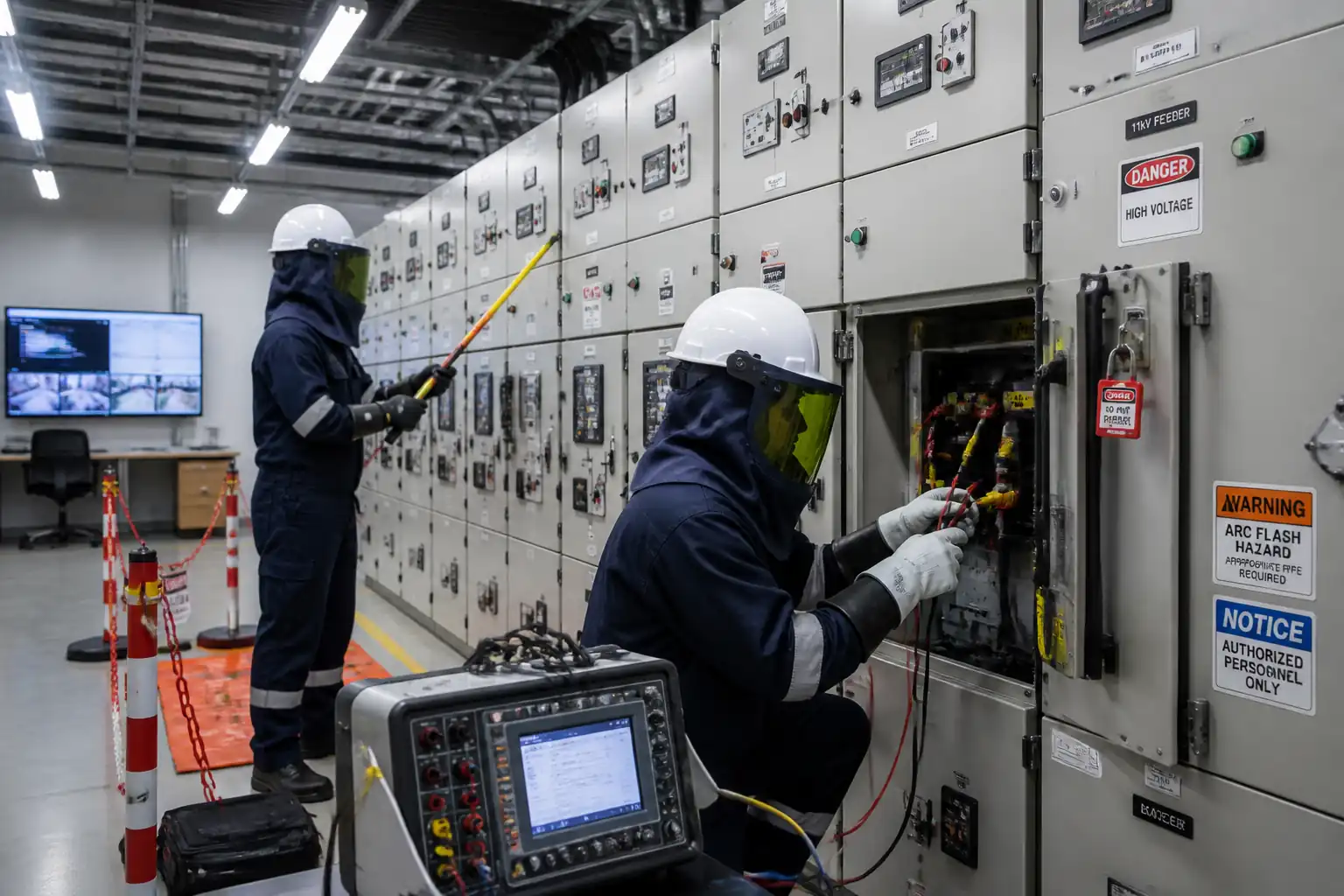
To ensure systematic, verified testing and safe energisation of HV RMU/switchgear in compliance with codes and project requirements.
Who uses this inspection and test plan
Contractor commissioning teams, HV Authorized Persons, Engineers/Consultants, and Utility/Authority representatives.
When this ITP is prepared and submitted
From pre-commissioning through post-energisation, culminating in handover.
Who receives or approves this ITP
The ITP is usually submitted to the client representative, consultant, resident engineer, or project management consultant for review and approval before the related work activity starts.
Inspection scope
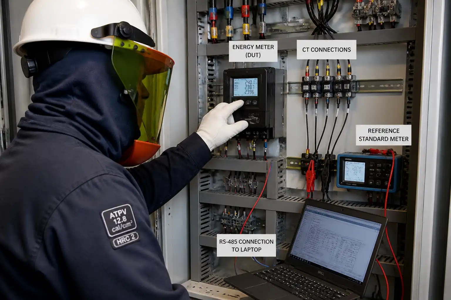
Permits, mechanical/electrical integrity, IR/contact resistance, CT/VT, interlocks, relay settings, secondary/primary injection, SCADA SAT, phasing, energisation, post-energisation checks.
Typical hold, witness, and review points
Hold: relay settings approval, phasing, final pre-energisation, energisation. Witness: interlocks, secondary/primary injection, SCADA SAT, thermography.
Typical inspection records
PTW/LOTO logs, checklists, test reports (IR, ductor, CT/VT, injection), SCADA SAT sheets, settings files, phasing certificate, switching log, SOE, thermography, as-builts.
Important approval note
This ITP is an AI-assisted editable starting point, not a pre-approved document. Before use on any project, all inspection activities, hold points, and acceptance criteria must be reviewed and approved by the relevant parties (superintendent, principal contractor, or client representative) in accordance with your contract and project quality plan.
Always verify acceptance criteria against your applicable drawings, specifications, and regulatory requirements. Hold points must be confirmed with the relevant authority before work proceeds past that point.
Inspection and test plan
| Activity | Inspection / Test | Acceptance Criteria | Responsibility | Record |
|---|---|---|---|---|
| Permits and pre-start briefing | Review of PTW/SFT/LOTO | Valid permits; LOTO applied; roles briefed and signed | Contractor (AP), HSE; Engineer/Client (W) | PTW/SFT forms; TBT record |
| Visual/mechanical inspection | Checklist & torque verification | No damage; torques per OEM; labels correct | Contractor; Engineer (W) | Pre-commissioning checklist; torque log |
| SF6 pressure and leak test (if applicable) | Gauge reading & leak detection | Pressure within OEM band; no leaks detected | Contractor/OEM; Engineer (W) | Gas log; leak test report |
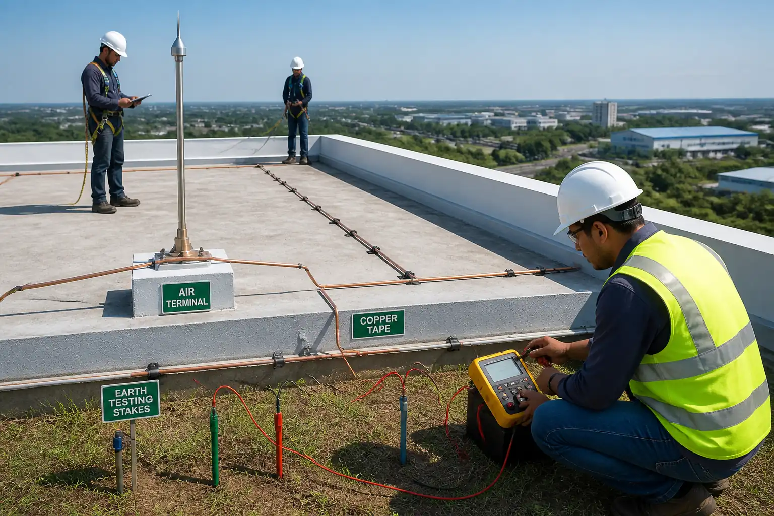
| Earthing continuity | Ductor test | Bonding ≤0.05 Ω [Verify] | Contractor; Engineer (W) | Earthing test report |
| Insulation resistance (MV and control) | IR at 5 kV (MV), 500–1000 V (control) | MV ≥100 MΩ; control ≥5 MΩ [Verify] | Contractor; Engineer (W) | IR test sheets |
| Contact resistance | Micro-ohm test 100 A | Within OEM value; phase balance ≤20% | Contractor; Engineer (W) | Contact resistance report |
| CT/VT polarity and ratio | Polarity/ratio tests | Correct polarity; class accuracy per IEC 61869 | Contractor (Protection); Engineer (W) | CT/VT test reports |
| Interlock verification | Functional demonstration | All interlocks effective; no unsafe bypass | Contractor/OEM; Engineer (W) | Interlock checklist |
| DC system and TCS check | Measurements and alarm tests | Voltage within ±3%; TCS healthy | Contractor; Engineer (W) | DC system report |
| Relay settings approval | Settings file review | Matches approved coordination study; checksum logged | Contractor; Engineer (H); Utility (W) | Settings approval sheet |
| Secondary injection testing | Secondary injection | Pickup/time within specified tolerances | Contractor (Protection); Engineer (W) | Secondary injection reports |
| Primary injection testing | Primary injection | End-to-end trip proven at setpoints ±5% | Contractor (Protection); Engineer (W) | Primary injection reports |
| SCADA/RTU points and commands | Point-to-point and command tests | 100% correct indications/commands; time sync ±1 s | Contractor (SCADA); Engineer/Client (W) | SCADA SAT sheets |
| Intertripping and scheme logic | Scheme trip tests | Trips/blocks as per logic; transfer time ≤50 ms [Verify] | Contractor; Engineer (W) | Scheme test report |
| Phasing and rotation check | Live phasing test | Correct ABC sequence; safe to parallel | Contractor (AP); Utility (H); Engineer (W) | Phasing certificate |
| Final pre-energisation review | Walkdown and checklist | No open NCRs; area safe; interlocks locked | Contractor; Engineer (H) | Pre-energisation checklist |
| Energisation and initial load take-up | Execution of switching program | No abnormal alarms/trips; parameters within expected range | Utility (H); Contractor (AP); Engineer (W) | Switching log; SOE records |
| Post-energisation thermography | Thermal scan | No hotspots >15°C delta-phase or >70°C absolute [Verify] | Contractor; Engineer (W) | Thermography report |
| Handover dossier | Document review | Complete and approved test/setting/as-built pack | Contractor; Engineer/Client (W) | Handover approval |
This table is a read-only public reference. Download the PDF or Excel version, or customize this ITP to edit it for your project.
Frequently asked questions
Related method statement
This Inspection and Test Plan is associated with the Method Statement: HV Switching and Commissioning of RMU/Switchgear method statement, which describes the step-by-step construction sequence, resources, materials, equipment, safety controls, and environmental controls for this activity.
View the Method Statement: HV Switching and Commissioning of RMU/Switchgear method statement →Continue with related inspection, method statement, article, and checklist resources.