
Method Statement for Placement of Ultra-High-Strength Structural Concrete (Grade 80 and above) for High-Rise Building Core Columns – Method Statement
AI-assisted method statement with matching ITP, PDF download, and Excel export.
More than a static template
Unlike a downloadable Word or PDF template, this method statement is an AI-assisted editable starting point connected directly to a matching Inspection and Test Plan. Every section is structured, project-adaptable, and ready to export.
- AI-assisted drafting — Customize every section with AI for your specific project scope.
- Linked ITP — A matching inspection and test plan is generated alongside the method statement.
- Multiple export formats — Download as a formatted PDF or editable Excel spreadsheet.
- Editable starting point, not a final document — Review, verify, and adjust all content against your project requirements before use.
Static template vs. Quollnet workflow
| Feature | Static template | Quollnet |
|---|---|---|
| Project-specific content | Manual fill-in required | AI-assisted customization |
| Linked ITP | Separate document, no link | Matching ITP included |
| Export formats | Usually PDF only | PDF and Excel |
| Structured sections | Free-form layout | 13 standardized sections |
| Saved to your account | Local file only | Cloud-saved, reusable |
| Content accuracy | You verify everything | AI-assisted, you still verify |
| Cost | Often free but time-intensive | Free to customize and download |
What you can customize
When you save this method statement to your account, every section becomes editable. The following 13 sections are included:
- Scope — Defines the activity and its boundaries.
- References — Standards, specifications, and drawings.
- Responsibilities — Roles and accountabilities.
- Resources — Labour, plant, and equipment summary.
- Materials — Materials and compliance requirements.
- Equipment — Tools and equipment details.
- Prerequisites — Hold points and pre-conditions.
- Method sequence — Step-by-step construction sequence.
- Safety controls — HSE risk controls and PPE.
- Environmental controls — Environmental mitigation measures.
- QA/QC — Quality inspection and test requirements.
- ITP — Inspection and Test Plan table (has its own page).
- Attachments — Referenced drawings and documentation.
Why this method statement is used
This method statement is used to define and communicate the approved procedure for carrying out method statement for placement of ultra-high-strength structural concrete (grade 80 and above) for high-rise building core columns on site. It ensures the work is planned in advance, the correct resources and controls are in place, and all personnel understand responsibilities, sequence, quality requirements, and safety controls before work begins. It aligns site execution with the documented scope and acceptance expectations.
Who uses this method statement
This method statement is used by contractors, site supervisors, project engineers, QA/QC engineers, HSE officers, consultants, and client representatives. It serves as a shared reference for planning, execution, supervision, inspection, and approval of the activity on site.
When it is prepared and submitted
The method statement is prepared before the work activity starts and submitted as part of the pre-construction documentation package for review and approval.
Who reviews or approves it
The method statement is usually submitted to the client representative, consultant, resident engineer, or project management consultant for review and approval before the work commences.
Important approval note
This method statement is an AI-assisted editable starting point, not a pre-approved document. Before use on any project, all content must be reviewed and approved by the relevant parties (superintendent, principal contractor, or client representative) in accordance with your contract and project quality plan.
For example: if your specification requires a departure from a referenced standard, that departure must be documented and approved separately — this method statement will not capture that automatically. Always verify against your applicable drawings, specifications, and regulatory requirements.
Method statement content
Scope
Overview
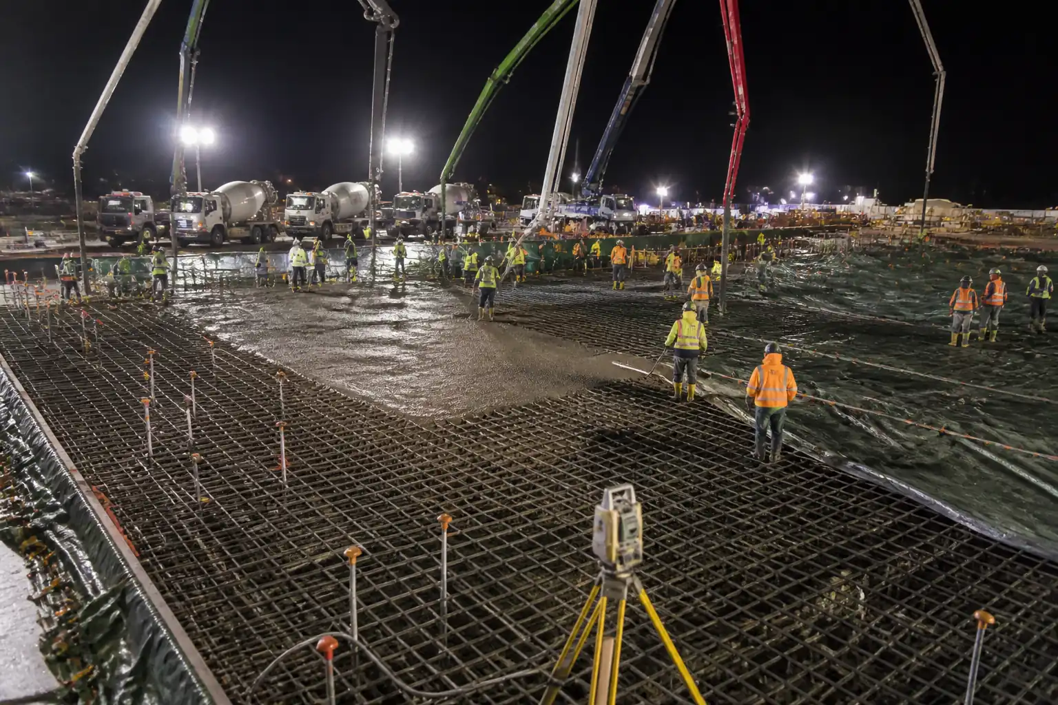
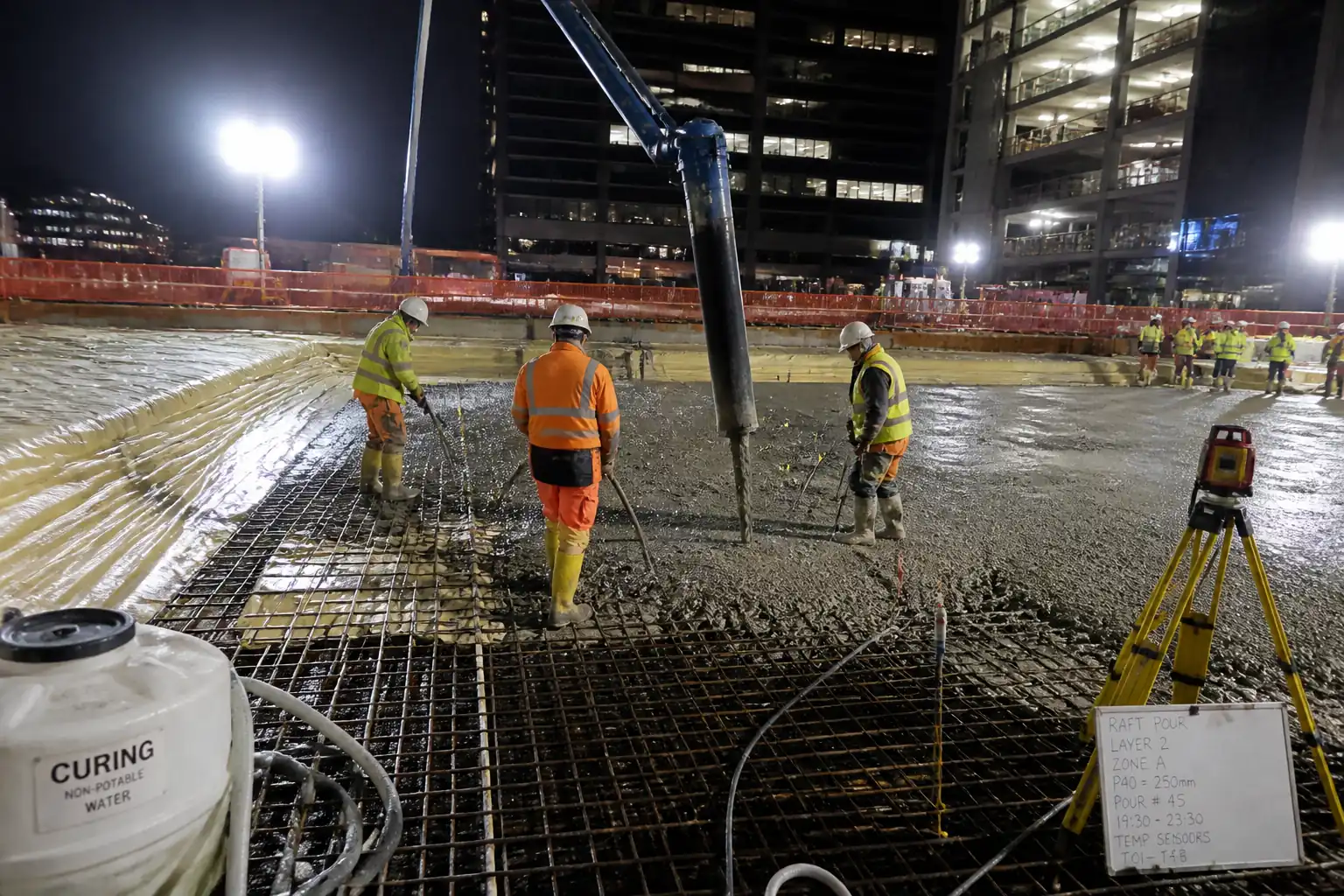
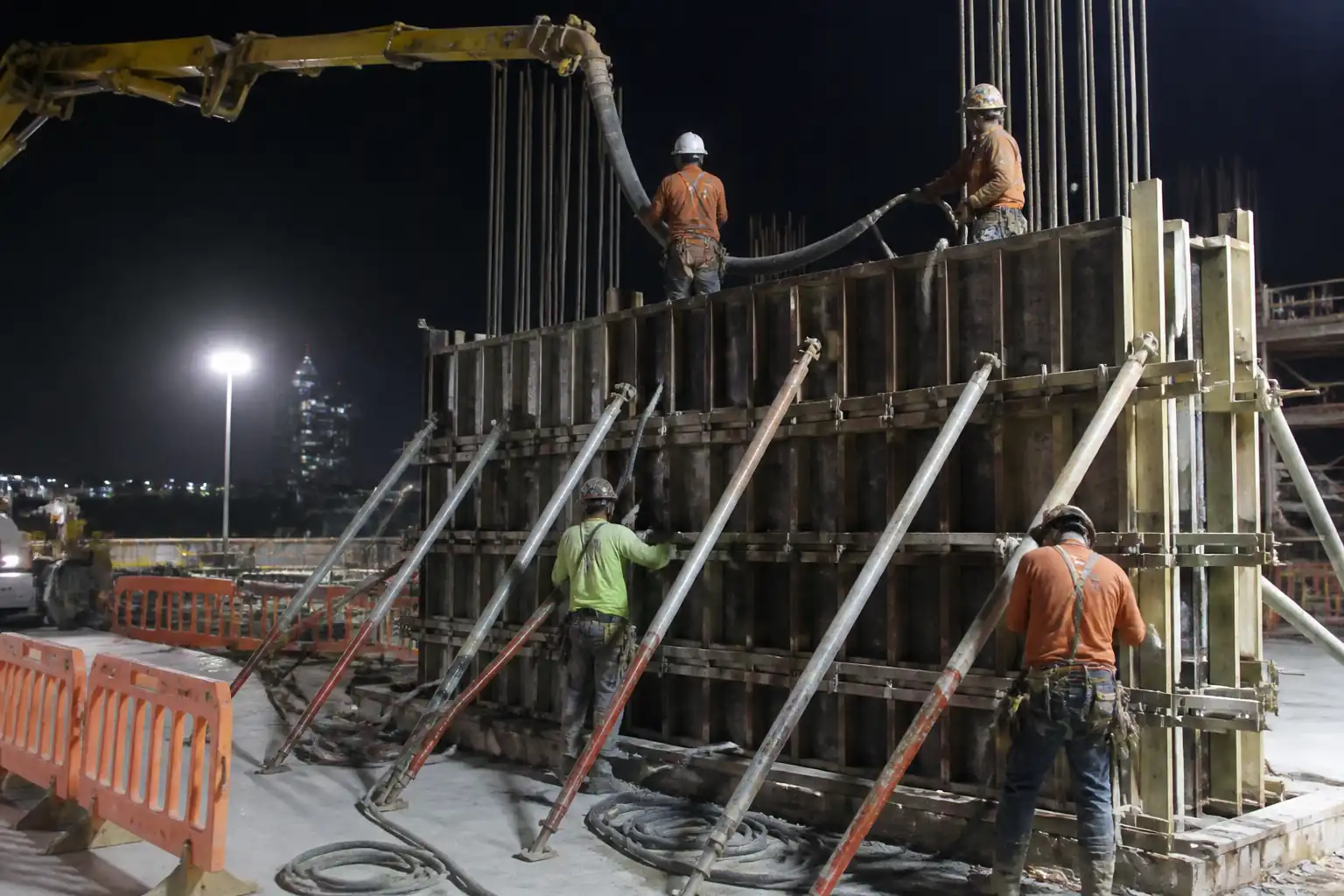
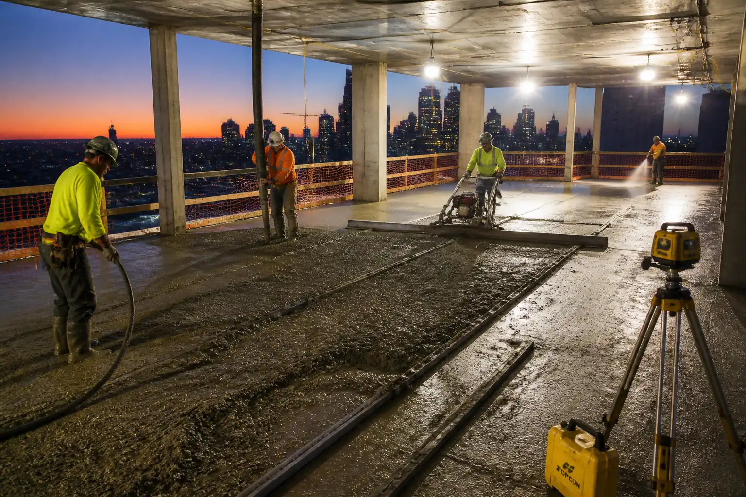
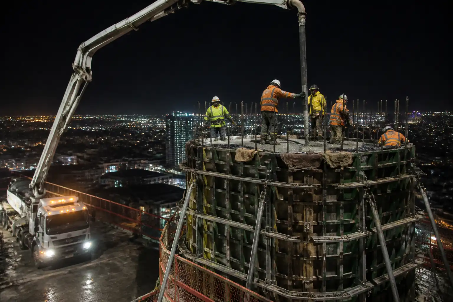
This method statement covers the end-to-end process for placing Ultra-High-Strength Concrete (UHSC) of design strength Grade 80 MPa and above in high-rise building core columns. It addresses production and delivery controls, pump placement logistics, formwork pressure management, high-shear consolidation in congested reinforcement, plasticizer loss tracking and controlled re-dosing, immediate curing actions to mitigate plastic shrinkage and early-age thermal/cracking risks, and conformance of pour zones and construction joints.
Inclusions
- UHSC mix verification, delivery, handling, and fresh-property testing
- Pumping, placement, consolidation in congested core reinforcement, rate-of-rise control
- Plasticizer (HRWR) retention monitoring and controlled on-site re-dosing
- Immediate and continuous curing, thermal monitoring, and protection
- Construction joint strategy and matching pour zones
- QA/QC, ITP, records, acceptance criteria, and survey of as-built plumbness/dimensions
Exclusions
- Foundation works, slabs, walls outside the core columns
- Post-tensioning operations (if any) beyond interface coordination
- Permanent formwork design (by others), but includes verification and pressure limits
Key Objectives
- Achieve specified compressive strength (f'c ≥ 80 MPa) and durability performance
- Ensure consolidation without segregation within highly congested reinforcement
- Prevent plastic shrinkage and early-age cracking through immediate curing and thermal control
- Maintain dimensional tolerances and plumbness per project requirements [Verify per project specifications]
References
| Document Type | Reference / Number | Revision | Notes |
|---|---|---|---|
| Standard | ACI 318 | ||
| Standard | ACI 301 | ||
| Guide | ACI 211.4R | ||
| Report | ACI 237R | Use as applicable for high-flow mixes. | |
| Report | ACI 309R | ||
| Guide/Spec | ACI 347 / ACI 347.2R | ||
| Report | ACI 305R | ||
| Report | ACI 306R | ||
| Standard | ASTM C94/C94M | ||
| Standards | ASTM C39, C31, C143, C1611, C138, C231, C173, C1064, C1074, C494, C150, C33, C1240 | ||
| Standard | ISO 9001 |
Responsibilities
| Role | Responsibility | Name / Party |
|---|---|---|
| PM | Lead | Main Contractor |
| CM | Control | Main Contractor |
| QA/QC | Verify | Main Contractor |
| SE | Execute | Main Contractor |
| FS | Execute | Specialist/Carpentry |
| Supplier QC | Verify | Ready-Mix Supplier |
| Lab | Test | Third Party |
| HSE | Lead HSE | Main Contractor |
| Survey | Execute | Main Contractor |
| Pump Crew | Execute | Pumping Subcontractor |
Resources
| Resource Type | Description | Quantity | Remarks |
|---|---|---|---|
| Personnel | 1 Foreman, 2 Hosemen, 2-3 Vibrator Operators, 2 General Laborers (per pump). | 7-8/ pump | |
| Personnel | 2-3 operatives dedicated to immediate top-surface curing and protection. | 2-3 | |
| Personnel | Sampling, fresh tests, cylinders/maturity sensors. | 1-2 |
Materials
| Material | Specification / Grade | Quantity | Remarks |
|---|---|---|---|
| Concrete | Include stability index for SCC (VSI ≤ 1) [Verify]. | ||
| Cement/SCMs | |||
| Aggregates | |||
| Admixtures | |||
| Curing | |||
| Release agent |
Equipment
| Equipment | Capacity / Type | Quantity | Inspection Required |
|---|---|---|---|
| Pump | 100–140 m³/h | 1 (plus standby if critical) | Yes |
| Hose | 1 per pump | Yes | |
| Vibrators | 3–4 | Yes | |
| External vibrators | As needed | Yes | |
| Weather kit | 1 | Yes | |
| Sensors | As plan | Yes | |
| Survey | 1 | Yes |
Prerequisites
Approvals and Preparations
- Approved mix design for UHSC (Grade ≥80 MPa), with documented trial results and admixture compatibility. Include slump/slump flow, segregation resistance, air content, and strength development curves.
- Formwork design verified for anticipated lateral pressures considering rate-of-rise and mix rheology; formwork inspection and release signed by responsible engineer.
- Pre-pour coordination meeting covering logistics, pour zones, rate-of-rise limits, curing strategy, test plan, plasticizer loss tracking, contingency for delays, and communication protocols.
- Access/egress and working platforms with edge protection; fall protection plans in place.
- Pump setup location agreed, line routing fixed/secured, exclusion zones marked, rescue route clear.
- Calibration certificates for testing equipment and sensors current.
- All embedded items, sleeves, rebar, and block-outs inspected and accepted; surfaces cleaned of debris and standing water.
- Permits: Hot/Cold weather concreting plan activated as required; night-work permit and lighting plan if applicable. [Verify per project HSE plan and local regulations]
- Materials on hand: curing media, evaporation retardant, covers, spare vibrators, backup generator.
- Weather assessment completed; evaporation rate calculated per ACI 305R; thermal monitoring plan issued.
Method Sequence
| Step | Activity | Description | Responsibility | Inspection / Hold Point |
|---|---|---|---|---|
| SEQ-01 | Pre-pour briefing and checks | Toolbox talk, confirm responsibilities, review rate-of-rise limit, emergency stop signals, confirm test frequencies, verify pour card data. | CM/QA-QC/HSE | Hold |
| SEQ-02 | Formwork readiness and pressure control plan | Check ties/bracing; install external vibrators if planned; seal joints; verify max placement rate per form pressure calc (typ. 1.5–2.0 m/h for UHSC/SCC) [Verify]. | FS/SE | Hold |
| SEQ-03 | Pump setup and priming | Lay and secure 125 mm pipeline; install anti-whip devices; prime with cement slurry (no water). Conduct pressure test. | Pump Crew | Witness |
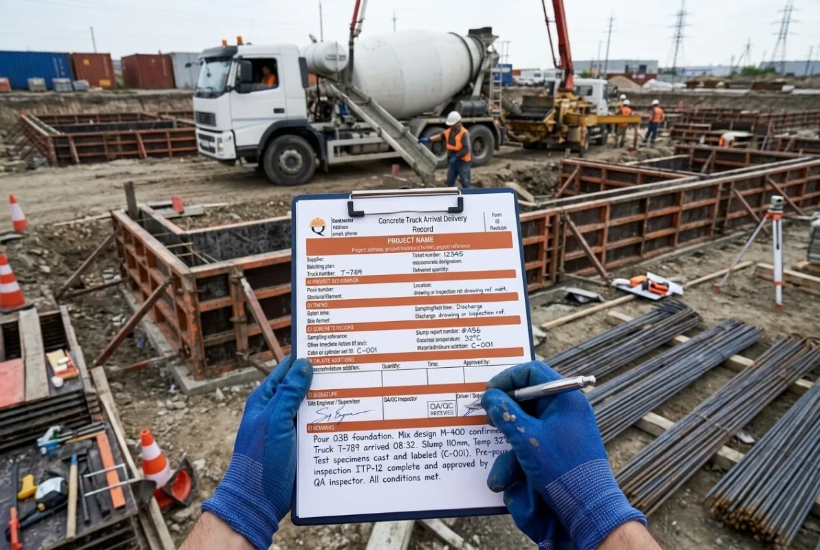
| SEQ-04 | Delivery verification and plasticizer loss tracking initiation | Check delivery tickets (time, mix ID, admixtures, water added at plant); start truck-by-truck Plasticizer Loss Tracking Log with ambient/concrete temp, slump/flow on arrival. | SE/Supplier QC | Witness |
| SEQ-05 | Fresh concrete tests (first truck and at frequency) | Slump (C143) or slump flow/T500 (C1611 for SCC), air (C231/C173), temp (C1064), density (C138). Frequency: first truck, every truck for slump/flow and temp; air/density at least every 50 m³ or every 2 trucks [Verify]. | Lab/QA-QC | Hold (first truck) |
| SEQ-06 | Controlled on-site HRWR re-dosing (if needed) | If slump loss >50 mm or flow loss >100 mm within 30 min, request Supplier QC approval; add HRWR within manufacturer total max dosage; mix 30–40 drum revs before re-test; strictly no water addition. | Supplier QC/SE | Witness |
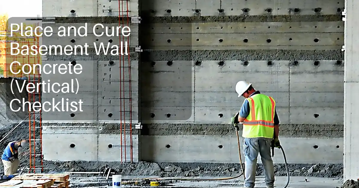
| SEQ-07 | Placement—lower lift | Place in 300–500 mm layers; keep drop height ≤ 1.5 m; start from one corner and progress systematically to avoid honeycombing. | SE/Hosemen | Surveillance |
| SEQ-08 | High-shear consolidation—internal vibration | Insert 25–38 mm vibrator at 300 mm spacing, penetrate 100 mm into previous layer, 5–15 s per insertion; avoid rebar contact; use pencil vibrators in congested cages; for SCC, avoid internal vibration except to remedy local blockages. | Vibrator Operators | Surveillance |
| SEQ-09 | Rate-of-rise and form pressure control | Monitor placement rate vs. allowed; adjust pump output; pause if signs of distress; for SCC assume near-hydrostatic pressure unless otherwise justified. | CM/FS | Surveillance |
| SEQ-10 | Matching pour zones and construction joint preparation | Place within defined zones; maintain live edges; if interruption >45 min or initial set imminent, stop and create joint: level surface, roughen, keep moist; later clean, remove laitance, apply approved bonding treatment if required [Verify]. | SE/QA-QC | Witness |
| SEQ-11 | Top-surface immediate curing | As soon as surface sheen disappears, apply evaporation retardant if E-rate >0.5 kg/m²/h; cover within 10 minutes with wet burlap + plastic. Avoid curing compound on future bond/joint surfaces. | Curing Crew | Surveillance |
| SEQ-12 | Ongoing curing and protection | Maintain moist cure ≥7 days or until 70% f'c achieved [Verify]; keep forms in place; prevent rapid cooling; protect from vibration/impact. | SE/QA-QC | Surveillance |
| SEQ-13 | Temperature monitoring | Install thermocouples core/surface; record max differential (typ. limit ≤20°C) and peak temperature limits [Verify]; adjust insulation/venting as needed. | QA/QC | Witness |
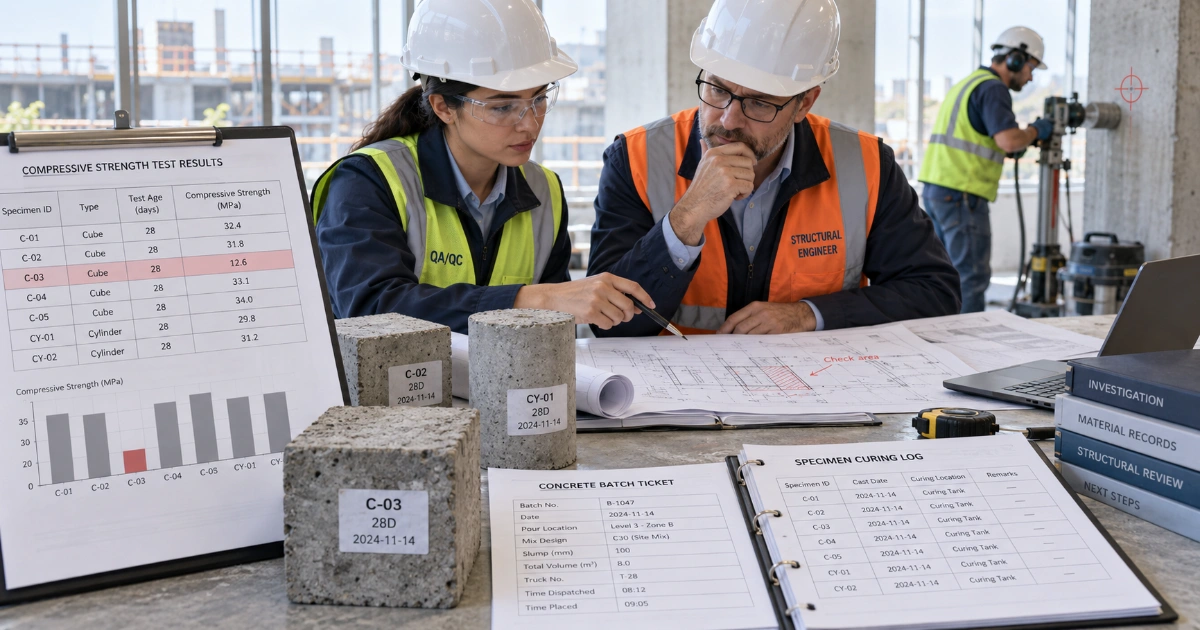
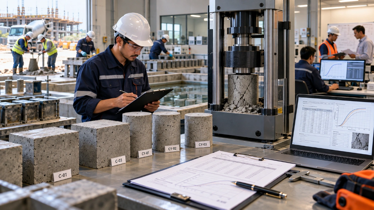
| SEQ-14 | Specimen preparation and testing | Cast cylinders (e.g., 6 per pour/section: 2 @7d, 2 @28d, 2 reserves) [Verify]; cure per ASTM C31; compressive tests per ASTM C39; maturity correlation if adopted. | Lab | Witness |
| SEQ-15 | Post-pour survey and inspection | Check dimensions, top elevation, and plumbness (target tolerance: typically ≤10 mm per 3 m and cumulative ≤25 mm for full height) [Verify]. | Survey/QA-QC | Witness |
| SEQ-16 | Formwork removal and surface evaluation | Strip when minimum stripping strength achieved (per calc or maturity) [Verify]; inspect for honeycombing/voids; repair per approved method if needed. | FS/QA-QC | Hold |
| SEQ-17 | Clean-up and waste management | Pump washout into contained tub; treat high-pH water; collect leftover concrete/cubes for proper disposal. | Pump Crew/HSE | Surveillance |
Health and Safety Controls
Key Task-Specific Hazards and Controls
- Hazard: Formwork over-pressurization and failure
- Likely consequence: Collapse, struck-by injuries, major structural damage
- Engineering/procedural control: Calculate allowable rate-of-rise; use pressure-equivalent approach for UHSC/SCC; inspect ties/bracing; stage placement; install external vibrators per plan (avoid resonance).
- Required PPE: Hard hat, safety boots, gloves, eye protection
- Collective preventive measure: Exclusion zones, physical barriers, warning signage
-
Inspection/permit/supervision: Formwork release by competent engineer; hold point before pour; continuous supervision by Formwork Supervisor. [Verify per project HSE plan and local regulations]
-
Hazard: Pump line rupture or hose whip
- Likely consequence: Impact injuries, concrete splatter/chemical burns
- Engineering/procedural control: Pressure test lines; secure clamps; anti-whip chains at end hose; avoid kinks; do not stand in line with hose; controlled start/stop communication.
- Required PPE: Hard hat, eye/face shield, long sleeves, chemical-resistant gloves
- Collective preventive measure: Pump exclusion zone with barriers; tag lines on hose; trained hosemen only
-
Inspection/permit/supervision: Pre-start pump checklist; supervisor and pump operator coordination; periodic clamp checks.
-
Hazard: Working at height on core platforms
- Likely consequence: Falls from height, serious injury/fatality
- Engineering/procedural control: Compliant guardrails, toe boards; fixed access ladders/stairs; fall arrest where guardrails incomplete; keep platforms clear of slurry.
- Required PPE: Full-body harness with double lanyard when required, non-slip boots
- Collective preventive measure: Edge protection systems; housekeeping; anti-slip mats
-
Inspection/permit/supervision: Work-at-height permit; daily scaffold/platform inspections by competent person.
-
Hazard: Concrete chemical burns and skin/eye irritation
- Likely consequence: Dermatitis, alkali burns, eye injury
- Engineering/procedural control: Provide wash stations; avoid direct contact; training on SDS; use neutralizing wipes where approved.
- Required PPE: Alkali-resistant gloves, long sleeves, goggles/face shield
- Collective preventive measure: Barrier creams; signage; eyewash stations
-
Inspection/permit/supervision: HSE inspections; SDS available on site.
-
Hazard: Congested reinforcement—vibrator entanglement and musculoskeletal strain
- Likely consequence: Hand-arm vibration syndrome, pinching, strains
- Engineering/procedural control: Use correct vibrator size/frequency; rotate operators; rest breaks; two-person handling for long durations.
- Required PPE: Anti-vibration gloves, hearing protection
- Collective preventive measure: Task rotation plan; mechanical supports for vibrators if feasible
-
Inspection/permit/supervision: Monitor exposure time; toolbox briefing on safe insertion technique.
-
Hazard: Rebar impalement and trip hazards
- Likely consequence: Puncture wounds, falls
- Engineering/procedural control: Cap exposed rebar; maintain tidy hose routes; illuminate at night.
- Required PPE: Hard hat, boots, gloves
- Collective preventive measure: Rebar caps, walkway delineation
-
Inspection/permit/supervision: Daily HSE walkdown; night-work permit if applicable.
-
Hazard: Noise from vibrators, pumps, generators
- Likely consequence: Hearing loss, fatigue
- Engineering/procedural control: Use compliant equipment; limit exposure time; position generators away from personnel.
- Required PPE: Hearing protection (SNR/NRR per risk assessment)
- Collective preventive measure: Noise barriers where practicable
-
Inspection/permit/supervision: Noise monitoring as required.
-
Hazard: Hot/cold weather exposure and thermal shock
- Likely consequence: Heat stress/hypothermia; thermal cracking of concrete
- Engineering/procedural control: Implement ACI 305/306 plans; shaded rest areas; control concrete placement temp; insulation/blankets on forms.
- Required PPE: Weather-appropriate PPE, hydration packs in hot weather
- Collective preventive measure: Work-rest regime; heated or cooled shelters
-
Inspection/permit/supervision: Environmental monitoring; supervisor checks.
-
Hazard: Mobile plant and delivery trucks interface
- Likely consequence: Struck-by/vehicle collision
- Engineering/procedural control: One-way traffic plan; banksman; spotters at pump reversals; speed limits.
- Required PPE: Hi-vis vest, hard hat, boots
- Collective preventive measure: Physical barriers and delineation
-
Inspection/permit/supervision: Traffic management plan; banksman certification.
-
Hazard: Electrical hazards from temporary power/lighting
- Likely consequence: Electrocution, fire
- Engineering/procedural control: RCD/GFCI protection; IP-rated fittings; cable management away from slurry.
- Required PPE: Dielectric gloves for electricians; standard PPE for others
- Collective preventive measure: Lock-out/tag-out where applicable
- Inspection/permit/supervision: Electrical permit-to-work; periodic PAT testing.
Environmental Controls
Environmental Risks and Controls
- Concrete washout and high-pH water
-
Control: Use lined containment trays/tubs; no discharge to ground/storm drains; treat/neutralize to acceptable pH before disposal. Record volumes and disposal route.
-
Admixture and fuel spills
-
Control: Store in bunded areas; spill kits adjacent; immediate containment and cleanup; reportable quantities per local regulations.
-
Noise during night pours
-
Control: Schedule within permitted hours; deploy acoustic barriers around pumps/generators; maintain equipment to reduce noise.
-
Dust and debris
-
Control: Keep workface tidy; use wet methods for joint surface prep; covered chutes for debris transfer.
-
Waste concrete and test specimens
-
Control: Collect and harden in designated bins; recycle where permitted; track manifests.
-
Energy and CO2 considerations
-
Control: Optimize truck dispatch to minimize idling; evaluate SCMs to reduce clinker intensity [Verify per project specifications].
-
Light pollution (if night works)
-
Control: Directional, shielded lighting focused on workface only.
-
Water use for curing/cleaning
- Control: Use recycled water where acceptable; minimize runoff from wet curing with edge containment.
QA/QC
Quality Objectives
- Meet or exceed specified compressive strength (f'c ≥ 80 MPa) and durability requirements.
- Maintain fresh properties within approved ranges suitable for congested placement without segregation.
- Achieve consolidation free of honeycombing and voids.
Testing and Frequencies [Verify per project specifications]
- Fresh properties: First truck and every truck for slump/flow and temperature; air and density at least every 50 m³ or every 2 trucks.
- Cylinders: Minimum 6 per pour/zone (7d, 28d, reserves); adjust per pour size.
- Temperature: Continuous logging core/surface at representative columns.
- Plumbness/dimensions: After initial set or within 24 h.
Acceptance Criteria
- Fresh concrete within approved tolerance ranges for slump/slump flow, air, temperature, and density.
- Strength: Per ACI 318 acceptance of strength test results (average of any three consecutive tests ≥ f'c; no individual test < f'c by more than 3.5 MPa) [Verify].
- Visual quality: No significant honeycombing; repair areas > specified limits per approved method.
Plasticizer Loss Tracking Protocol
- Log for each truck: batch time, arrival time, ambient and concrete temperature, initial slump/flow, VSI (if SCC), admixtures dosed at plant, any on-site HRWR re-dose (amount, time), re-test results.
- Trigger for evaluation: slump loss >50 mm or flow loss >100 mm within 30 min; prohibited actions: water addition.
- Re-dosing controls: Total HRWR dosage not to exceed manufacturer/project limit (e.g., ≤2% by mass of cementitious) [Verify]; minimum 30–40 revolutions before re-testing per ASTM C94.
Curing Controls
- Immediate top-surface cover within 10 minutes of finishing; maintain moisture continuity for ≥7 days or until 70% f'c [Verify].
- Thermal differential target: typically ≤20°C between core and surface [Verify].
Documentation
- Pre-pour checklist, formwork release, pump checklist, delivery tickets, plasticizer tracking log, fresh test reports, cylinder logs, temperature/maturity logs, curing log, as-built survey, NCR/CCR as needed.
Attachments
- Example Pre-Pour Checklist (core columns UHSC)
- Plasticizer Loss Tracking Log template (per truck)
- Curing Log template and Evaporation Rate Calculator sheet
- Pump Setup and Pressure Test Checklist
- Inspection Request (IR) form for rebar/embeds/formwork
- Nonconformance Report (NCR) template and Corrective Action Report (CAR)
- Temperature/Maturity Sensor Installation sketch
- Pour Zone and Construction Joint plan (project-specific)
This content is a read-only public reference. Download or customize to get an editable version.
ITP preview
The first inspection activities from the linked ITP for Method Statement for Placement of Ultra-High-Strength Structural Concrete (Grade 80 and above) for High-Rise Building Core Columns:
| Activity | Inspection / Test | Acceptance Criteria | Responsibility | Record |
|---|---|---|---|---|
| Mix design approval and trial results | Document review | Approved UHSC mix with verified performance data. | QA/QC Manager / Designer / Supplier QC | Approval letter; trial mix reports |
| Formwork readiness and rate-of-rise limit | Visual/engineering check | Formwork release; documented max placement rate. | Formwork Engineer / QA/QC | Formwork release; calc summary |
| Rebar and embed inspection | Visual/measurement | As per approved drawings; clean and secured. | Site Engineer / QA/QC / Designer rep (if required) | IR/Inspection checklist; photos |
Showing 3 of 14 inspection activities. View full ITP →
Related Inspection and Test Plan
An Inspection and Test Plan (ITP) is available for Method Statement for Placement of Ultra-High-Strength Structural Concrete (Grade 80 and above) for High-Rise Building Core Columns. The ITP defines the inspection activities, acceptance criteria, hold and witness points, responsible parties, and records required to verify the work described in this method statement.
View the Method Statement for Placement of Ultra-High-Strength Structural Concrete (Grade 80 and above) for High-Rise Building Core Columns ITP →Frequently asked questions
Continue with related Quollnet resources connected to this method statement.