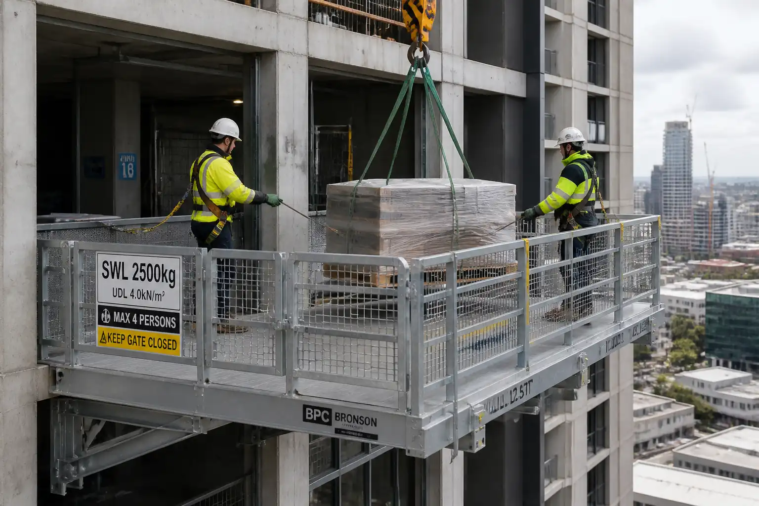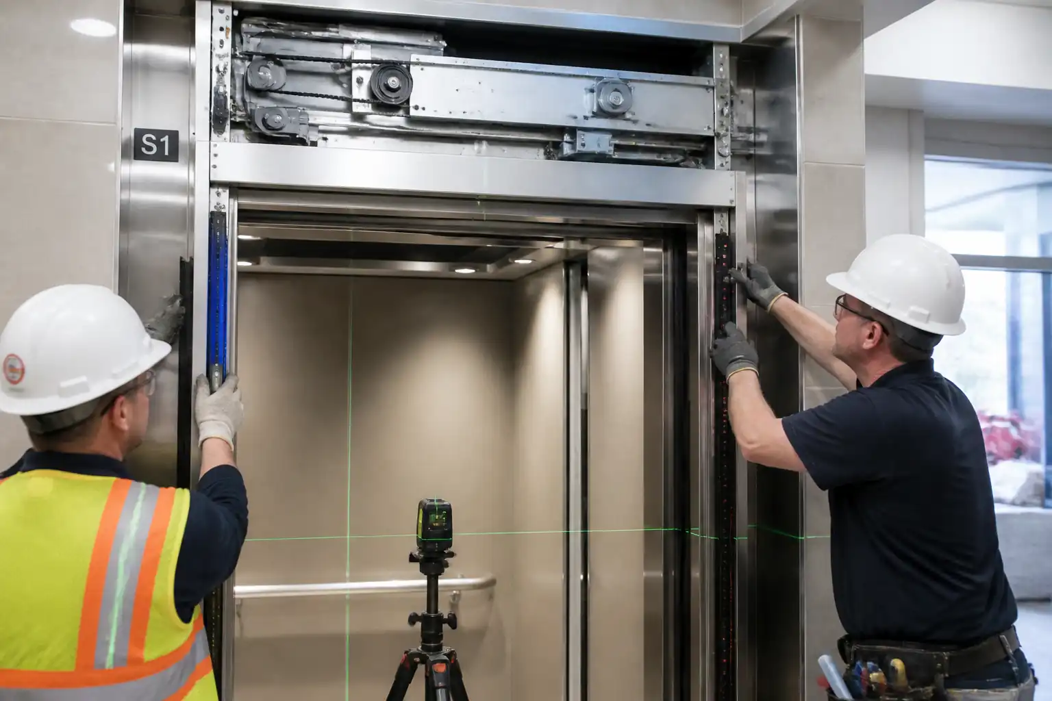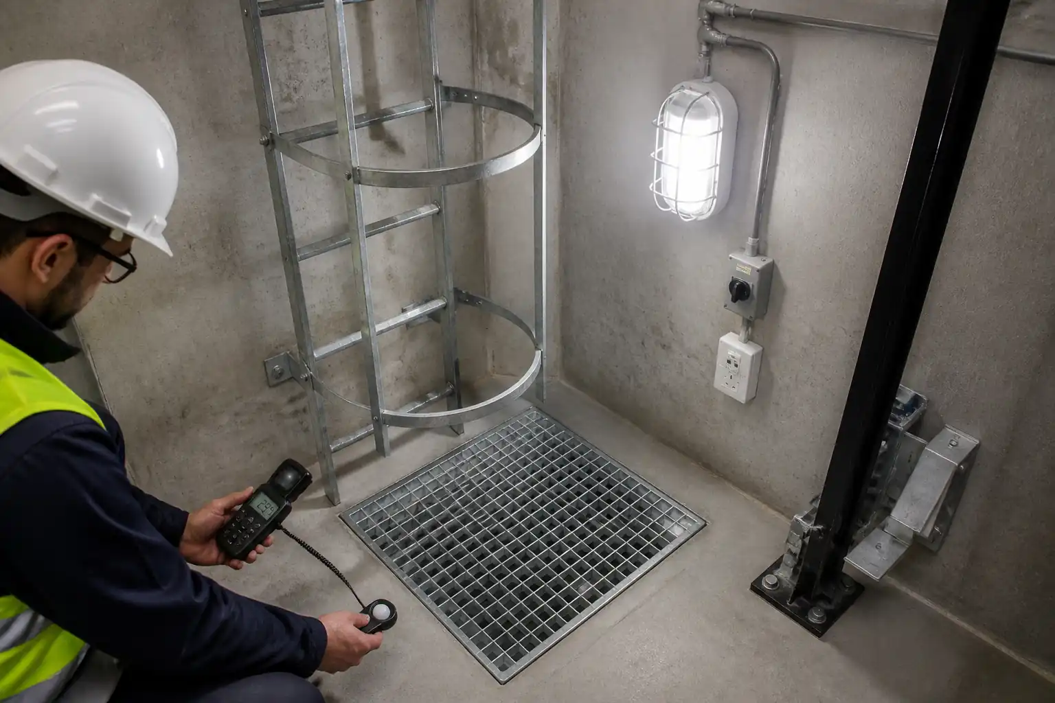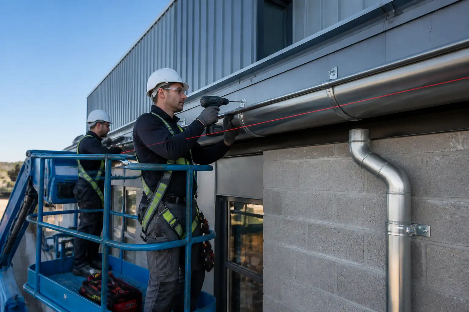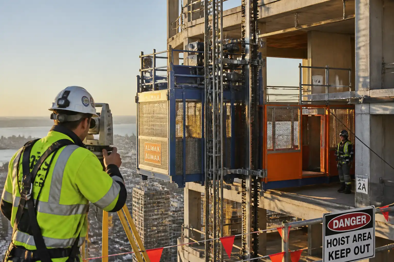

Method Statement: External Rack-and-Pinion Material Hoist Installation, Building Anchor Testing, Mast Verticality, Overspeed Safety Brake Drop Test, and Gate Interlock Checks – Method Statement
AI-assisted method statement with matching ITP, PDF download, and Excel export.
More than a static template
Unlike a downloadable Word or PDF template, this method statement is an AI-assisted editable starting point connected directly to a matching Inspection and Test Plan. Every section is structured, project-adaptable, and ready to export.
- AI-assisted drafting — Customize every section with AI for your specific project scope.
- Linked ITP — A matching inspection and test plan is generated alongside the method statement.
- Multiple export formats — Download as a formatted PDF or editable Excel spreadsheet.
- Editable starting point, not a final document — Review, verify, and adjust all content against your project requirements before use.
Static template vs. Quollnet workflow
| Feature | Static template | Quollnet |
|---|---|---|
| Project-specific content | Manual fill-in required | AI-assisted customization |
| Linked ITP | Separate document, no link | Matching ITP included |
| Export formats | Usually PDF only | PDF and Excel |
| Structured sections | Free-form layout | 13 standardized sections |
| Saved to your account | Local file only | Cloud-saved, reusable |
| Content accuracy | You verify everything | AI-assisted, you still verify |
| Cost | Often free but time-intensive | Free to customize and download |
What you can customize
When you save this method statement to your account, every section becomes editable. The following 13 sections are included:
- Scope — Defines the activity and its boundaries.
- References — Standards, specifications, and drawings.
- Responsibilities — Roles and accountabilities.
- Resources — Labour, plant, and equipment summary.
- Materials — Materials and compliance requirements.
- Equipment — Tools and equipment details.
- Prerequisites — Hold points and pre-conditions.
- Method sequence — Step-by-step construction sequence.
- Safety controls — HSE risk controls and PPE.
- Environmental controls — Environmental mitigation measures.
- QA/QC — Quality inspection and test requirements.
- ITP — Inspection and Test Plan table (has its own page).
- Attachments — Referenced drawings and documentation.
Why this method statement is used
This method statement is used to define and communicate the approved procedure for carrying out method statement: external rack-and-pinion material hoist installation, building anchor testing, mast verticality, overspeed safety brake drop test, and gate interlock checks on site. It ensures the work is planned in advance, the correct resources and controls are in place, and all personnel understand responsibilities, sequence, quality requirements, and safety controls before work begins. It aligns site execution with the documented scope and acceptance expectations.
Who uses this method statement
This method statement is used by contractors, site supervisors, project engineers, QA/QC engineers, HSE officers, consultants, and client representatives. It serves as a shared reference for planning, execution, supervision, inspection, and approval of the activity on site.
When it is prepared and submitted
The method statement is prepared before the work activity starts and submitted as part of the pre-construction documentation package for review and approval.
Who reviews or approves it
The method statement is usually submitted to the client representative, consultant, resident engineer, or project management consultant for review and approval before the work commences.
Important approval note
This method statement is an AI-assisted editable starting point, not a pre-approved document. Before use on any project, all content must be reviewed and approved by the relevant parties (superintendent, principal contractor, or client representative) in accordance with your contract and project quality plan.
For example: if your specification requires a departure from a referenced standard, that departure must be documented and approved separately — this method statement will not capture that automatically. Always verify against your applicable drawings, specifications, and regulatory requirements.
Method statement content
Scope
Overview
This method covers the complete installation, inspection, testing, and commissioning of an external vertical rack-and-pinion material hoist including:
- Foundation/base frame installation and leveling
- Mast erection and tie-in brackets to building slabs/structure
- Slab/structure anchor drilling, setting, pull-out proof testing, and torque checks
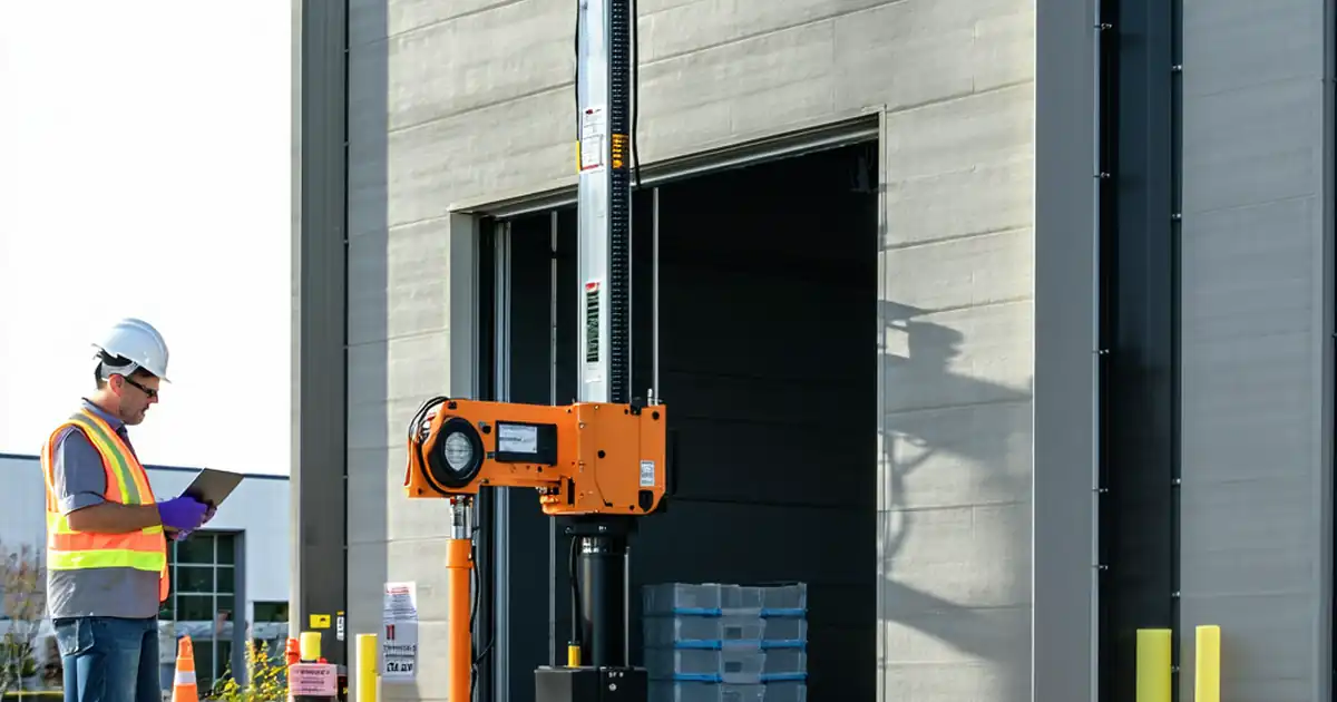
- Mast verticality verification using laser plummet/theodolite
- Electrical installation, earthing, and functional checks
- Overspeed safety brake drop testing with rated load
- Landing gate and car door interlock functional checks
- Final load test, documentation, and handover
Exclusions
- Permanent building structural works other than tie-in anchorage preparation
- Permanent power supply beyond agreed isolator/feeder
- Hoist operation after handover (operations manual covered separately)
Key Objectives
- Install and certify the hoist safely, accurately, and in compliance with standards and manufacturer instructions
- Demonstrate anchor performance, mast plumb tolerance, safety gear function, and interlock integrity
- Produce complete QA/ITP records for Client acceptance and third-party certification
[All values and tolerances to be verified per project specifications and manufacturer’s data].
References
| Document Type | Reference / Number | Revision | Notes |
|---|---|---|---|
| Standard | BS EN 12158-1 | [Verify applicability: material-only vs persons+materials] | |
| Standard | BS EN 12159 | Apply where hoist is rated for persons and materials; otherwise use manufacturer’s limits | |
| Standard | BS 8539 | Proof-load levels and sampling to be verified per anchor manufacturer | |
| Standard | EN 1992-4 | Design by qualified structural engineer | |
| Standard | ASTM E488/E488M | Use where US practice applies or specified | |
| Standard | IEC 60204-1 | ||
| Standard | ISO 13849-1 | Manufacturer to declare PL for safety circuits | |
| Manual | Make/Model: [Insert] | Hold latest approved issue on site | |
| Contract | Spec Sections: [Insert] | Overrides generic guidance where stricter |
Responsibilities
| Role | Responsibility | Name / Party |
|---|---|---|
| PM | Ensure schedule, budget, and contractual compliance | Contractor |
| SE | Base level/plumb control, tie spacing and embedment checks | Contractor |
| AP | Method and risk assessment for mast lifts | Contractor |
| Supervisor/Rigger | Tag lines, exclusion zones, signaling | Contractor |
| Fitters | Apply correct torque, sequence, and manufacturer procedures | Supplier/Subcontractor |
| Electrician | Comply with IEC 60204-1 and OEM diagrams | Contractor/Supplier |
| QA/QC | Witness tests, maintain records, NCRs | Contractor |
| HSE | Task-specific RA, PTW, supervision | Contractor |
| Inspector | Certify hoist before service | Independent |
| Engineer | Approve results at hold points | Client/Engineer |
Resources
| Resource Type | Description | Quantity | Remarks |
|---|---|---|---|
| Manpower | OEM-trained personnel | 4–8 [Verify] | |
| Manpower | Industrial controls experience | 2–3 [Verify] | |
| Manpower | Laser/theodolite plumb control | 1 | |
| Manpower | Appointed Person, Supervisor, Riggers, Banksman | As plan |
Materials
| Material | Specification / Grade | Quantity | Remarks |
|---|---|---|---|
| Anchor bolts/studs | BS 8539; EN 1992-4; ETA/ICC ESR | As per tie layout | |
| Cementitious grout | ASTM C1107 Type C or equivalent | As required | |
| Fasteners | ISO 898-1; ISO 4014/4017 | Per OEM | |
| Cables & devices | IEC 60204-1; IEC 60364 [Verify] | As design | |
| OEM assemblies | OEM | Per layout |
Equipment
| Equipment | Capacity / Type | Quantity | Inspection Required |
|---|---|---|---|
| Crane/telehandler | [Insert] t | 1 | Pre-lift inspection |
| MEWP | As required | Daily check | |
| Torque wrench | Up to 1000 N·m [Verify] | 2–3 sizes | Calibration cert |
| Tester | Up to 200 kN [Verify] | 1 | Calibration cert |
| Survey instrument | 1 | Calibration cert | |
| DMM & IR | IR 250–1000 V ranges | 1 set | Calibration cert |
| Test kit | 1 | Calibration cert | |
| Drill | 2 | Daily check |
Prerequisites
- Approved shop drawings, tie layout, and structural calculations signed by a qualified engineer.
- Manufacturer’s IOM and assembly drawings (latest revision) available on site.
- PTW/RA/JSA approved for lifting, working at height, electrical works, and drop test [Verify per project HSE plan and local regulations].
- Base/foundation readiness: concrete strength test results meeting design (e.g., f'c ≥ 30 MPa) and minimum curing age achieved [Verify].
- Survey control points established for base level and mast plumb reference.
- Power supply confirmed (voltage, phase, short-circuit rating), isolator installed, earthing verified.
- All lifting equipment, torque wrenches, gauges, meters, and data loggers with current calibration certificates.
- Exclusion zones, barriers, signage, and debris netting/edge protection installed.
- Weather window within limits: wind for erection ≤ 10–12 m/s, dry conditions; lightning protocol in place [Verify].
- Anchor system approved (type, size, embedment, edge distances), test plan agreed (proof loads, sampling).
- Emergency and rescue plan briefed; first aid and fire extinguishers available.
- Waste and environmental controls set (dust extraction, spill kits, resin waste containers).
Method Sequence
| Step | Activity | Description | Responsibility | Inspection / Hold Point |
|---|---|---|---|---|
| 1 | Site setup and verification | Establish exclusion zone, deliver components, verify permits, brief team with toolbox talk | Site Engineer / HSE / Supervisor | HSE pre-start checklist |
| 2 | Base frame positioning and leveling | Set base frame on prepared foundation/ballast; shim and level | Fitters / Site Engineer | Survey level check |
| 3 | Base anchorage installation | Drill holes to specified diameter and depth; clean using brush-blow-brush; install anchors per BS 8539/OEM | Fitters | Hole cleaning and embedment check |
| 4 | Base grout placement (if specified) | Dry pack or flowable non-shrink grout under base plates after preliminary torque | Fitters | Grout mixing records; bearing checks |
| 5 | Anchor torque and/or proof load test (base) | Torque to OEM value; proof-load test representative anchors as required | QA/QC / Site Engineer | Torque wrench calibration; pull tester setup |
| 6 | Mast section erection (initial bays) | Lift first mast sections; connect with bolts; install rack segments; temporary guying if required | Fitters / Lifting Team | Bolt grade/length; washer orientation |
| 7 | Install tie frames and slab/structure anchors (first tie) | Mark tie locations; drill and install anchors; fit tie frame to structure | Fitters / Electrician (if powered tie) | Embedment and edge checks |
| 8 | Tie anchor proof testing and torque checks | Hydraulic tension test of each tie anchor or agreed sampling; torque fasteners to specified N·m | QA/QC / Site Engineer | Gauge zeroing; displacement measurement |
| 9 | Progressive mast erection and subsequent ties | Repeat mast addition in lifts; install ties at each level as per layout | Fitters | Periodic torque checks |
| 10 | Mast verticality survey | Use laser plummet/theodolite to check plumb after each tie and at final height | Surveyor / Site Engineer | Survey instrument calibration |
| 11 | Cage/drive unit installation | Install car, motor/gearbox, pinions, limit cams; set clearances and lubrication | Fitters | Gear mesh and rack alignment |
| 12 | Electrical installation | Connect power/control circuits, earthing, landing calls, interlocks, overspeed trip circuit | Electrician | Wiring per diagrams; gland/terminations |
| 13 | No-load functional tests | Power-up; test travel, limits (top/bottom), E-stops, door/gate interlocks without load | Electrician / Commissioning Engineer | Signal simulation |
| 14 | Landing gate interlock checks | At each landing, verify closed/locked-only enable; opening any gate stops car and prevents restart | Electrician / QA/QC | Function test and attempt to bypass |
| 15 | Rated load test (travel) | Load car to rated capacity using test weights; verify running speed, braking distance, and stability | Commissioning Engineer / QA/QC | Speed with tachometer |
| 16 | Overspeed safety brake drop test | Conduct controlled overspeed trip per OEM: raise car, initiate overspeed, record deceleration and stopping distance | Commissioning Engineer / Third-Party | Data logger setup; exclusion zone |
| 17 | Final torque re-check | Re-torque all accessible structural and tie bolts post-tests | Fitters / QA/QC | Spot-check 10–20% after full recheck |
| 18 | Documentation and handover | Compile records, as-built tie layout, calibration, certificates; third-party examination | QA/QC / Supplier | Document review |
Safety Controls
Principal Hazards and Controls
1) Lifting and handling of mast sections and cage
- Hazard: Dropped loads, crane overturning, pinch/crush injuries
- Likely consequence: Serious injury/fatality, equipment damage
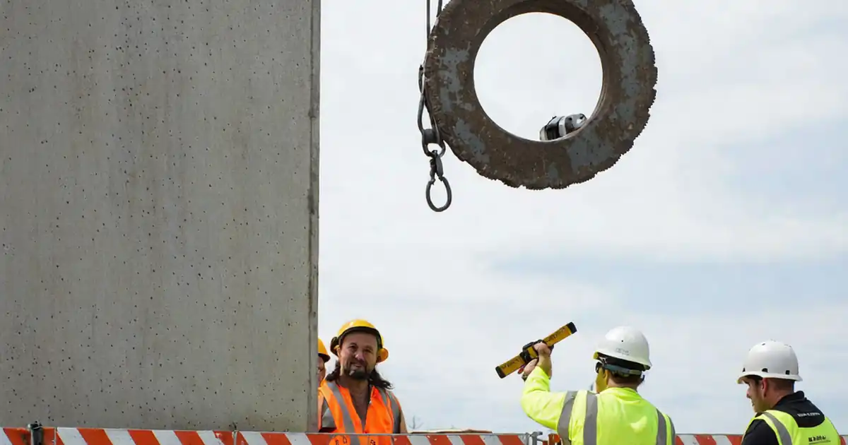
- Engineering/procedural controls: Appointed Person lift plan, certified crane with adequate capacity and radius margin, tag lines, exclusion zone equal to minimum twice load height footprint, no personnel under suspended load, wind limit ≤ 10–12 m/s for lifts [Verify].
- Required PPE: Hard hat with chin strap, cut-resistant gloves, safety boots, eye protection, hi-vis; hearing protection near crane
- Collective measures: Barriers, spotters/banksman, radio comms
- Inspection/permit/supervision: Daily crane/rigging inspections, LOLER/ASME certs [Verify per local], Lifting PTW, Lifting Supervisor present
2) Working at height (ties, mast assembly)
- Hazard: Falls from MEWP/edges; falling objects
- Consequence: Severe injury/fatality
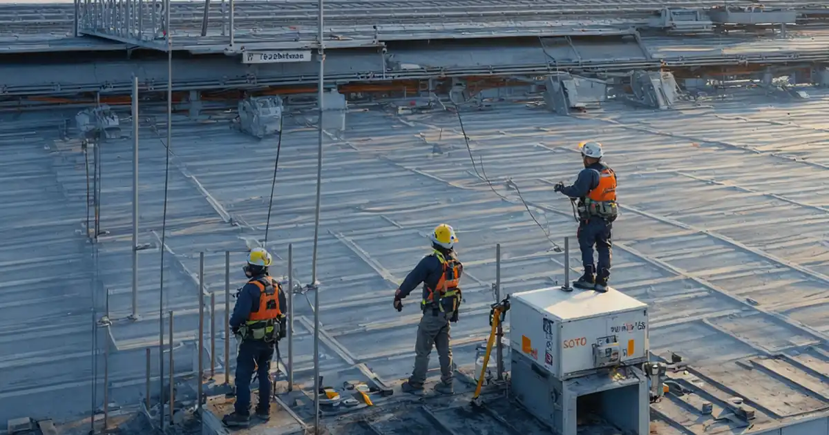
- Controls: Use MEWP with harness and short lanyard (≤ 1.8 m), edge protection/netting, tool lanyards, secure small parts in pouches, designated material transfer points
- PPE: Full-body harness with lanyard, helmet with chin strap, gloves, boots, eye protection
- Collective measures: MEWP secondary guarding, exclusion zones below
- Inspection/permit/supervision: Work at Height PTW; MEWP daily inspection; competent operator; HSE supervision
3) Drilling and installing anchors
- Hazard: Hitting rebar or embedded services; silica dust; kickback
- Consequence: Structural damage; respiratory illness; hand injuries
- Controls: Scan/rebar detection where feasible; consult as-built drawings; drill with two-handed rotary hammer and side handle; dust extraction (HEPA); vacuum cleanup; confirm hole diameter/depth with stop collars
- PPE: Cut-resistant gloves, safety glasses/goggles, FFP3/N95 respirator, hearing protection
- Collective measures: Local exhaust ventilation, debris collection trays
- Inspection/permit/supervision: Hot works not applicable; authorisation to drill into structure; QA check on each hole
4) Electrical works and energization
- Hazard: Electric shock, arc, unintended movement
- Consequence: Serious injury/fatality
- Controls: Lockout/Tagout; verify absence of voltage before work; finger-safe terminals; IP-rated enclosures; interlocked isolator; test with calibrated meters; use 24 V DC safety circuits where designed
- PPE: Insulated gloves (where required), eye protection, arc-rated PPE if applicable [Verify]
- Collective measures: Barriers around live testing; key-controlled isolators
- Inspection/permit/supervision: Electrical PTW; competent electrician; records of IR/continuity tests
5) Overspeed safety brake drop test
- Hazard: Sudden deceleration, falling objects, structural loads to ties
- Consequence: Injury/death if in drop zone; equipment damage if malfunction
- Controls: Exclusion zone extending full hoist height plus 5 m perimeter; only essential personnel present; secure test loads; follow OEM test method; pre-test inspection of ties and mast; install secondary fall-arrest device if specified by OEM
- PPE: Helmets with chin strap, gloves, boots, eye and hearing protection
- Collective measures: Radio comms, emergency stop manned, test conducted under supervision of Competent Examiner
- Inspection/permit/supervision: Dedicated PTW for drop test; QA/HSE presence; Third-Party witness hold point
6) Weather exposure and wind loads
- Hazard: Loss of control during lifts; hoist sway during erection
- Consequence: Collision, structural damage
- Controls: Defined wind limits for erection and testing; stop works during lightning/heavy rain; secure mast overnight; additional temporary guys if required by OEM
- PPE: Weather-appropriate PPE, anti-slip footwear
- Collective measures: Anemometer on site; daily weather briefing
- Inspection/permit/supervision: Supervisor to monitor winds; record suspensions
7) Pinch/entanglement with rack and pinion
- Hazard: Hands or clothing caught in moving parts
- Consequence: Severe injury
- Controls: Guards in place before energization; lockout during mechanical setting; signage and no-go zones
- PPE: Close-fitting clothing, gloves appropriate to task
- Collective measures: Interlocked access panels; key control
- Inspection/permit/supervision: Pre-start guard inspection; supervisor sign-off
8) Public interface/adjacent property
- Hazard: Unauthorized access, debris egress
- Consequence: Public injury; claims
- Controls: Hoarding, locked gates, security, debris nets, night lighting; schedule noisy works within permitted hours
- PPE: Not applicable to public; workforce as above
- Collective measures: Clear wayfinding, warning signage
- Inspection/permit/supervision: Local authority permits; HSE inspections [Verify per local regulations]
9) Manual handling of components
- Hazard: Strains, crush injuries
- Consequence: Musculoskeletal disorders
- Controls: Use mechanical aids; team lifts; keep hands clear; plan set-down areas
- PPE: Gloves, boots
- Collective measures: Handling aids/trolleys
- Inspection/permit/supervision: Manual handling training; supervisor monitoring
10) Chemical anchors and lubricants
- Hazard: Skin/eye irritation; VOCs; improper curing
- Consequence: Health effects; anchor failure
- Controls: SDS compliance; mixing/dispensing per OEM; temperature-curing chart posted; waste capsules disposed as hazardous waste
- PPE: Chemical-resistant gloves, eye protection, long sleeves
- Collective measures: Spill kits; ventilation
- Inspection/permit/supervision: SDS on site; HSE checks
Environmental Controls
- Dust control: Use on-tool extraction and HEPA vacuums during drilling; wet-wipe cleanup; no dry sweeping.
- Noise management: Schedule drilling and impact works within permitted hours; provide hearing protection; monitor dB(A) if near sensitive receptors.
- Waste management: Segregate scrap metal, packaging, and timber; collect spent resin cartridges and oily rags as hazardous waste; dispose via licensed carriers.
- Spill prevention: Store oils/grease on drip trays; provide spill kits; immediate cleanup and reporting of spills.
- Water/slurry control: Capture drilling slurry; prevent discharge to drains; use filter socks or containers for settlement before disposal.
- Energy and emissions: Keep plant well-maintained; avoid idling; use electric tools where practicable.
- Visual/oversailing impacts: Maintain tidy laydown; secure materials against wind; hoarding with project information.
- Compliance: Follow project EMP, local environmental permits, and reporting requirements [Verify per project HSE plan and local regulations].
QA/QC
Key Quality Requirements
- Drawings/Design: Only approved for construction (AFC) documents used. Any deviation requires TQ/RFI and designer approval.
- Calibration: All torque wrenches, pull-testers, meters, and survey instruments must have valid calibration certificates.
- Base Level: Tolerance 1 mm/m; overall base flatness deviation ≤ 3 mm [Verify].
- Anchors:
- Drilling: Diameter and embedment per anchor ETA/ICC and design.
- Cleaning: Brush-blow-brush sequence; verify hole cleanliness visually.
- Proof testing: Recommended 100% of safety-critical tie anchors; proof load 1.25–1.5 × service load; hold for 1 minute; displacement ≤ 0.5–1.0 mm with no continuous creep [Verify per BS 8539/ASTM E488 and OEM].
- Torque: 100% torque verification of nuts/bolts; record actual N·m.
- Mast Verticality: After each tie and at final height: ≤ 1:1000 of total height; local step at any tie ≤ 3 mm; overall offset ≤ 25 mm [Verify OEM].
- Fasteners: Correct grade and length; apply OEM torque; use thread locking where specified; re-torque after 24–48 hours and after first 1–2 weeks of service [Verify].
- Electrical: Continuity and polarity correct; insulation resistance ≥ 1 MΩ at appropriate test voltage per IEC 60204-1 [Verify]; earth continuity < 0.1 Ω typical [Verify].
- Interlocks: Functional integrity proven at each landing; opening any gate stops motion and prevents restart until faults cleared and reset.
- Overspeed Drop Test: Trip at OEM/EN threshold (e.g., 115–140% rated speed); stopping distance/mean deceleration within OEM/EN limits; post-test inspection of pinions, racks, ties, and anchors – no damage or loosening.
- Documentation: Complete ITP checklists, torque logs, pull-test reports, survey reports, electrical test sheets, calibration certs, OEM declarations, third-party certificate of thorough examination [Verify per local regulation].
Attachments
- Example forms: Anchor installation sheet; Anchor pull-test report; Bolt torque log; Verticality survey sheet; Electrical test sheet; Interlock checklist; Drop test certificate template.
- Approved shop drawings and tie layout with coordinates and elevations.
- Manufacturer’s IOM manuals and parts lists (model/serial numbers).
- Calculations: Tie loads, anchor design per EN 1992-4; base reactions; wind load checks.
- Lift plan and rigging drawings; crane certificates.
- Calibration certificates for torque wrenches, pull-testers, survey instruments, meters, decelerometer, tachometer.
- HSE documentation: Risk Assessment/JSA, Method Statement, PTWs, Emergency/Rescue Plan, Inductions and TBT records.
- Regulatory and compliance: Third-Party Examination Certificate; local authority permits; environmental permits if applicable.
This content is a read-only public reference. Download or customize to get an editable version.
ITP preview
The first inspection activities from the linked ITP for Method Statement: External Rack-and-Pinion Material Hoist Installation, Building Anchor Testing, Mast Verticality, Overspeed Safety Brake Drop Test, and Gate Interlock Checks:
| Activity | Inspection / Test | Acceptance Criteria | Responsibility | Record |
|---|---|---|---|---|
| Base foundation readiness | Level measurement; review cube tests | Level/flatness within tolerance; f'c meets design [Verify] | Site Engineer / QA/QC | Pre-pour/ready-for-install report |
| Base frame installation and level | Level readings at four corners | ≤ 1 mm/m; overall ≤ 3 mm | Site Engineer / QA/QC | Survey log |
| Base anchors installation | Gauge depth; visual cleanliness | Per BS 8539/EN 1992-4 and OEM | QA/QC / Fitters | Anchor install sheet |
Showing 3 of 14 inspection activities. View full ITP →
Related Inspection and Test Plan
An Inspection and Test Plan (ITP) is available for Method Statement: External Rack-and-Pinion Material Hoist Installation, Building Anchor Testing, Mast Verticality, Overspeed Safety Brake Drop Test, and Gate Interlock Checks. The ITP defines the inspection activities, acceptance criteria, hold and witness points, responsible parties, and records required to verify the work described in this method statement.
View the Method Statement: External Rack-and-Pinion Material Hoist Installation, Building Anchor Testing, Mast Verticality, Overspeed Safety Brake Drop Test, and Gate Interlock Checks ITP →Frequently asked questions
Continue with related Quollnet resources connected to this method statement.