
Method Statement: Lift Pit Ladder, Lighting and Sump Cover Installation – Method Statement
AI-assisted method statement with matching ITP, PDF download, and Excel export.
More than a static template
Unlike a downloadable Word or PDF template, this method statement is an AI-assisted editable starting point connected directly to a matching Inspection and Test Plan. Every section is structured, project-adaptable, and ready to export.
- AI-assisted drafting — Customize every section with AI for your specific project scope.
- Linked ITP — A matching inspection and test plan is generated alongside the method statement.
- Multiple export formats — Download as a formatted PDF or editable Excel spreadsheet.
- Editable starting point, not a final document — Review, verify, and adjust all content against your project requirements before use.
Static template vs. Quollnet workflow
| Feature | Static template | Quollnet |
|---|---|---|
| Project-specific content | Manual fill-in required | AI-assisted customization |
| Linked ITP | Separate document, no link | Matching ITP included |
| Export formats | Usually PDF only | PDF and Excel |
| Structured sections | Free-form layout | 13 standardized sections |
| Saved to your account | Local file only | Cloud-saved, reusable |
| Content accuracy | You verify everything | AI-assisted, you still verify |
| Cost | Often free but time-intensive | Free to customize and download |
What you can customize
When you save this method statement to your account, every section becomes editable. The following 13 sections are included:
- Scope — Defines the activity and its boundaries.
- References — Standards, specifications, and drawings.
- Responsibilities — Roles and accountabilities.
- Resources — Labour, plant, and equipment summary.
- Materials — Materials and compliance requirements.
- Equipment — Tools and equipment details.
- Prerequisites — Hold points and pre-conditions.
- Method sequence — Step-by-step construction sequence.
- Safety controls — HSE risk controls and PPE.
- Environmental controls — Environmental mitigation measures.
- QA/QC — Quality inspection and test requirements.
- ITP — Inspection and Test Plan table (has its own page).
- Attachments — Referenced drawings and documentation.
Why this method statement is used
This method statement is used to define and communicate the approved procedure for carrying out method statement: lift pit ladder, lighting and sump cover installation on site. It ensures the work is planned in advance, the correct resources and controls are in place, and all personnel understand responsibilities, sequence, quality requirements, and safety controls before work begins. It aligns site execution with the documented scope and acceptance expectations.
Who uses this method statement
This method statement is used by contractors, site supervisors, project engineers, QA/QC engineers, HSE officers, consultants, and client representatives. It serves as a shared reference for planning, execution, supervision, inspection, and approval of the activity on site.
When it is prepared and submitted
The method statement is prepared before the work activity starts and submitted as part of the pre-construction documentation package for review and approval.
Who reviews or approves it
The method statement is usually submitted to the client representative, consultant, resident engineer, or project management consultant for review and approval before the work commences.
Important approval note
This method statement is an AI-assisted editable starting point, not a pre-approved document. Before use on any project, all content must be reviewed and approved by the relevant parties (superintendent, principal contractor, or client representative) in accordance with your contract and project quality plan.
For example: if your specification requires a departure from a referenced standard, that departure must be documented and approved separately — this method statement will not capture that automatically. Always verify against your applicable drawings, specifications, and regulatory requirements.
Method statement content
Scope
Work Summary
- Supply, install, test, and hand over:
- Fixed steel ladder in lift pit including safety hoops/cage (where required by local code) and wall stand-offs.
- Pit lighting fixture with protective guard, local light switch, and RCD/GFCI-protected receptacle in weatherproof enclosure.
- Open-grid galvanized sump cover and support frame at pit sump.
- Perform verification tests:
- Pit illumination level measurement at defined grid points.
- Ladder rung proof-load/weight-bearing check.
- Electrical tests: continuity, insulation resistance, polarity, RCD/GFCI trip, and earthing/grounding.
- Produce as-builts, test records, and O&M documentation.
Exclusions/Interfaces
- Elevator equipment supply/commissioning by Elevator Contractor.
- Permanent power energization by Electrical Contractor/Utility.
- Civil repair of major structural defects beyond minor patching.
Key Assumptions
- Pit structure is cast and at design strength; access is coordinated and car is immobilized/secured by Elevator Contractor.
- Voltage and receptacle standard per project (e.g., 230 V~ IEC or 120 V~ NEC) [Verify per project specifications].
- Safety hoops/cage requirements vary by jurisdiction; apply ISO/EN or local code as applicable [Verify per project specifications].
References
| Document Type | Reference / Number | Revision | Notes |
|---|---|---|---|
| Standard | EN 81-20/EN 81-50 Safety rules for the construction and installation of lifts [Verify per project specifications] | Pit access, lighting, receptacle and ladder provisions. | |
| Code | ASME A17.1/CSA B44 Safety Code for Elevators and Escalators [Verify per project specifications] | North America; pit lighting min levels and receptacle, access ladder. | |
| Standard | ISO 14122-4 Safety of machinery – Permanent means of access to machinery – Part 4: Fixed ladders | Rung spacing, clearance, cage/hoops, strength. | |
| Standard | BS 4211 Fixed ladders – Specification [Verify applicability] | Dimensions and loads. | |
| Standard | IEC 60364 Low-voltage electrical installations; IEC 60598 Luminaires; IEC 61008/61009 RCDs | Circuit protection, IP ratings, RCD performance. | |
| Code | NFPA 70 (NEC) – Articles 110, 210, 250, 410 [Verify applicability] | GFCI, grounding, fixtures, receptacles. | |
| Standard | BS 4592 Metal open bar grating; alternatively EN 1991-1-1 imposed loads for floors [Verify] | Loading classes and slip resistance. | |
| Assessment | ETA/ETAG or ICC-ES reports for post-installed anchors (e.g., bonded anchors) | Design loads, installation method, proof testing. | |
| Standard | ISO 45001 OHSMS; Local regulations for confined space, electrical safety, and work at height [Verify] |
Responsibilities
| Role | Responsibility | Name / Party |
|---|---|---|
| Project Manager | Project Manager | Main Contractor |
| Site Engineer | Site Engineer (Civil/Architectural) | Main Contractor |
| Electrical Supervisor | Electrical Supervisor/Foreman | Main Contractor/MEP |
| QA/QC Engineer | QA/QC Engineer | Main Contractor |
| HSE Officer | HSE Officer | Main Contractor |
| Surveyor | Land Surveyor | Main Contractor |
| Elevator Contractor | Elevator Contractor Representative | Nominated Subcontractor |
| Engineer/Consultant | Engineer/Consultant | Employer/Engineer |
| Storekeeper | Storekeeper | Main Contractor |
Resources
| Resource Type | Description | Quantity | Remarks |
|---|---|---|---|
| Manpower | 2 steel/metal workers for ladder and grating | 2 | |
| Manpower | 2 electricians + 1 helper | 3 | |
| Manpower | HSE Officer and QA/QC Engineer shared across area | 2 | |
| Manpower | Surveyor for setout/plumb check | 1 |
Materials
| Material | Specification / Grade | Quantity | Remarks |
|---|---|---|---|
| Fixed ladder | Compliant with ISO 14122-4/BS 4211/EN 81-20 [Verify]. | 1 set per pit | Width ≥ 400 mm; rung spacing 250–300 mm; clearance behind rungs ≥ 200 mm; side rail standoffs to wall ≥ 150 mm [Verify per ISO 14122-4]. |
| Chemical anchors + studs/washers/nuts | ETA/ICC-ES approved system (e.g., epoxy) for cracked concrete; service temp per datasheet. | As per design | Typical M10–M12; embedment 70–100 mm; min edge distance/spacing per ETA [Verify]. |
| Luminaires | IEC 60598 compliant; corrosion-resistant body; 230 V~ or 120 V~ per project. | 1 per pit or as specified | Ingress protection ≥ IP65; IK08 or higher; CCT 4000–5000 K [Verify]. |
| Switch + RCD/GFCI-protected socket-outlet | IEC 61008/61009 or UL 943 compliant; IP65 minimum. | 1 set per pit | RCD/GFCI 30 mA residual current; receptacle rating 16 A (IEC) or 15 A (NEMA) [Verify]. |
| Cables + galvanized conduit or PVCu heavy-duty | IEC 60364 compliant; flame retardant; green/yellow PE conductor provided. | As required | Cable type: PVC/SWA/PVC or LSZH as project; conductor size per load/voltage drop [Verify]. |
| Grating + angle/flat bar frame | BS 4592 or equivalent; HDG per ISO 1461. | 1 assembly per sump | Clear opening to suit sump; UDL ≥ 5 kN/m² and point load ≥ 1.5 kN [Verify]. |
| Labels | Project signage standard. | As required | UV-resistant, engraved/laminated. |
| Corrosion protection | ISO 1461/ISO 12944 guidelines. | As required | Zinc-rich paint ≥90% Zn by weight in dry film [Verify]. |
Equipment
| Equipment | Capacity / Type | Quantity | Inspection Required |
|---|---|---|---|
| Rotary hammer | 1 | ||
| Cleaning kit | 1 set | ||
| Torque wrench | 1 | ||
| Pull tester | Up to 10 kN | 1 | |
| Test instruments | 1 set | ||
| Lux meter | 1 | ||
| Access equipment | As required | ||
| Gas detector | 1 |
Prerequisites
Approvals and Documentation
- Approved shop drawings, data sheets, and method statement/ITP.
- Anchor design or selection verified by Engineer with ETA/ICC-ES documentation for substrate conditions.
- Material inspection upon delivery with mill/test certificates and IP/IK ratings for electrical equipment.
- Calibrations current for all test instruments and torque/pull testers.
Permits and Coordination
- Permit to Work including LOTO for any electrical interfaces; energization only under Electrical Supervisor control.
- Lift car immobilized and shaft access authorized by Elevator Contractor; safe access to pit arranged.
- Confined Space Permit if pit classified as such [Verify per project HSE plan and local regulations].
Site Readiness
- Pit structure complete, clean, dry as practicable; concrete strength ≥ 25 MPa [Verify] and thickness adequate for anchors (≥150 mm recommended [Verify]).
- Pit dimensions and ladder location verified; check no clash with buffers, guide rails, sump, or car under-travel envelope.
- Temporary lighting and ventilation arranged if permanent supply not available.
- All utilities in the pit identified and protected.
Tools and Materials Staging
- Pre-assemble ladder hoops/cage and verify dimensions.
- Pre-fit luminaires with guards, switches, and boxes; prepare labels.
- Pre-cut grating to suit opening where possible; if site cutting needed, prepare hot-work permit and protection.
Method Sequence
| Step | Activity | Description | Responsibility | Inspection / Hold Point |
|---|---|---|---|---|
| 1 | Pre-start HSE briefing and permits | Conduct TBT specific to lift pit; confirm LOTO, elevator immobilization, confined space classification, emergency plan, and gas test if applicable. | HSE Officer / Site Engineer | Permit to Work check |
| 2 | Setting out and mark-up | Mark ladder location, top and bottom landings, standoff brackets; verify clearances to car path and equipment; mark sump cover frame lines. | Site Engineer / Surveyor | Dimensional check |
| 3 | Drill and install anchor sleeves/studs (ladder brackets) | Drill per anchor system; clean holes 2x blow–2x brush–2x blow; inject adhesive; insert studs to marked embedment using setting tool; observe gel time. | Metalworker / Site Engineer | In-process |
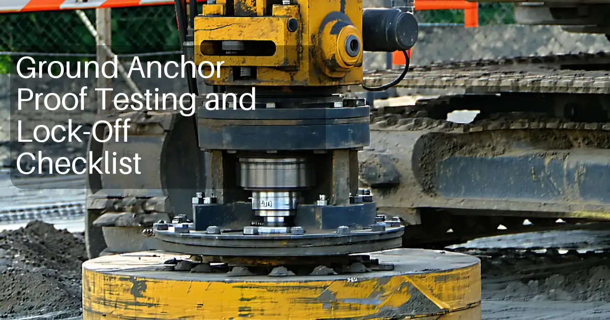
| 4 | Anchor proof testing (sample) | After cure, proof-load sample anchors (min 10% or 3 anchors, whichever is greater) with portable tester. | QA/QC Engineer | Hold point |
| 5 | Fix ladder brackets/stand-offs | Position brackets; tighten nuts to manufacturer torque using calibrated wrench; apply thread locking if specified. | Metalworker | Torque check |
| 6 | Install ladder and safety hoops/cage | Hoist ladder into position; secure to brackets; assemble hoops at specified intervals (typ. 900–1500 mm) with vertical backrail; ensure clearances. | Metalworker / Site Engineer | Dimensional check |
| 7 | Touch-up galvanizing and edges | Clean and apply zinc-rich paint to cut/drilled areas per manufacturer DFT; cure per datasheet. | Metalworker | Coating check |
| 8 | Install pit light with guard and switch | Mount luminaire at wall/underside as drawing; height to avoid damage by car; run conduit/cable to local switch and supply. | Electrical Supervisor | In-process |
| 9 | Install GFCI/RCD-protected receptacle | Fix weatherproof box; wire via dedicated circuit or local RCD module per design; label circuit ID and test sticker. | Electrical Supervisor | In-process |
| 10 | Earthing/grounding and bonding | Bond ladder, grating/frame, and metallic conduits to nearest earthing point with approved clamps/conductors. | Electrical Supervisor | Continuity test |
| 11 | Fabricate and install sump cover and frame | Install galvanized angle frame level with surrounding slab; place serrated grating with hold-down clips; ensure easy removal and anti-lift feature. | Metalworker / Site Engineer | Dimensional and seating check |
| 12 | Electrical testing and energization | Perform IR test, continuity, polarity; function test light and switch; test RCD/GFCI trip time using tester; record results; energize circuit. | Electrical Supervisor / QA/QC | Hold point |
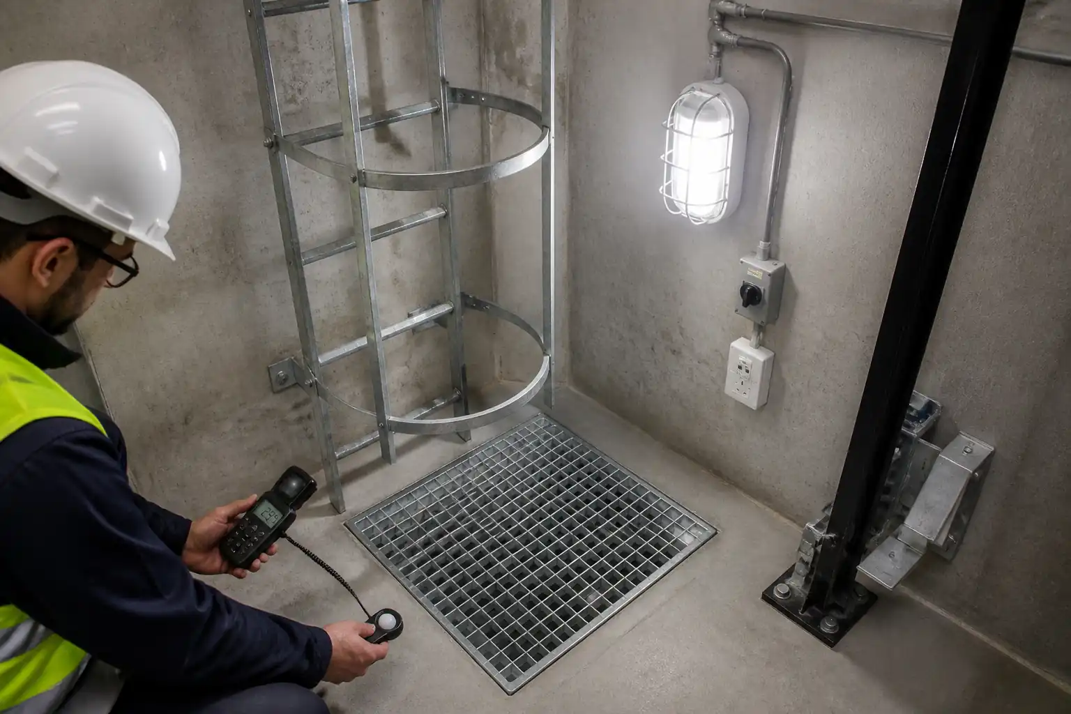
| 13 | Illumination level test | Measure illuminance at pit floor at min 4 points plus center with lux meter, lights stabilized (≥5 min). | QA/QC Engineer | Witness/Record |
| 14 | Ladder proof-load check | Apply static load at mid-span of a representative rung using load device or sandbag jig. | QA/QC Engineer / Third-party (if required) | Hold point |
| 15 | Housekeeping and demobilization | Remove debris, adhesives, metal swarf; restore finishes; remove temporary access; update redlines. | Site Engineer | Final check |
| 16 | Handover and documentation | Submit as-built drawings, data sheets, warranties, test records, inspection checklists, O&M manuals. | Project Manager / QA/QC | Client/Consultant review |
Health and Safety Controls
Task-Specific Hazard Controls
- Hazard: Accessing elevator pit and interaction with lift equipment
- Likely consequence: Crushing by moving car/counterweight; entrapment
- Engineering/procedural control: Elevator Contractor to immobilize car with approved blocking/maintenance mode; isolate shaft equipment; lockable pit stop switch; PTW and LOTO; authorize access only after confirmation
- Required PPE: Helmet with chin strap, gloves, safety boots, eye protection
- Collective preventive measure: Barricade and signage at landing doors; attendant on duty during works
-
Inspection/permit/supervision: PTW check; Elevator Contractor sign-off; Supervisor presence throughout
-
Hazard: Fall into pit or from ladder during installation
- Likely consequence: Fractures, serious injury
- Engineering/procedural control: Use temporary certified access platform/working platform; maintain three-point contact; fix ladder progressively from bottom; do not stand on unfixed ladder
- Required PPE: Fall-arrest harness with short lanyard if working near unprotected edges; non-slip footwear
- Collective preventive measure: Edge protection/temporary guardrails where feasible
-
Inspection/permit/supervision: Pre-use inspection of access equipment; HSE supervision
-
Hazard: Drilling into concrete (silica dust, flying debris, noise)
- Likely consequence: Respiratory harm, eye injury, hearing loss
- Engineering/procedural control: Use on-tool extraction/vacuum; wet drilling if permitted; use sharp bits and depth stops; exclude sparks if near elevator components
- Required PPE: FFP2/FFP3 respirator, safety goggles/face shield, hearing protection, gloves
- Collective preventive measure: Local ventilation in pit; debris containment
-
Inspection/permit/supervision: Tool PAT and guard checks; HSE inspections
-
Hazard: Chemical anchor resin handling
- Likely consequence: Skin/eye irritation, sensitization
- Engineering/procedural control: Follow SDS; use dispensing tool; avoid skin contact; provide spill kit; cure time observed before loading
- Required PPE: Chemical-resistant gloves, goggles, long sleeves
- Collective preventive measure: Secondary containment for cartridges; ventilation
-
Inspection/permit/supervision: SDS available; COSHH/chemical permit [Verify per local regulations]
-
Hazard: Electrical shock during installation/testing
- Likely consequence: Electrocution, burns
- Engineering/procedural control: De-energize circuits before connection; test for dead; lock-off; use RCD/GFCI; only qualified electricians to work
- Required PPE: Insulated gloves (as required), dielectric-rated tools, eye protection
- Collective preventive measure: Barriers and lock boxes; residual current protection
-
Inspection/permit/supervision: Electrical PTW; supervision by Electrical Supervisor; test instrument calibration
-
Hazard: Hot work (if grating cutting on site)
- Likely consequence: Fire, burns, fumes
- Engineering/procedural control: Hot work permit; fire watch; non-flammable blankets; fume extraction
- Required PPE: Flame-resistant clothing, welding shield/face protection, gloves
- Collective preventive measure: Fire extinguishers; spark containment
-
Inspection/permit/supervision: Hot work permit and gas test if required; fire watch sign-off
-
Hazard: Manual handling of ladder/grating
- Likely consequence: Musculoskeletal strain, crush injuries
- Engineering/procedural control: Team lift; use chain block or small hoist; plan path; keep hands clear
- Required PPE: Gloves, safety boots
- Collective preventive measure: Mechanical aids; clear walkways
-
Inspection/permit/supervision: Manual handling briefing; supervisor oversight
-
Hazard: Confined space atmosphere (if applicable)
- Likely consequence: Hypoxia, toxic exposure
- Engineering/procedural control: Gas test (O2, LEL, H2S/CO as applicable); forced ventilation; standby attendant; rescue plan
- Required PPE: Gas detector for entrant, harness for retrieval if required
- Collective preventive measure: Tripod/retrieval system if designated confined space
-
Inspection/permit/supervision: Confined Space Permit; continuous monitoring [Verify per project HSE plan and local regulations]
-
Hazard: Sharp edges and slip hazards on grating
- Likely consequence: Cuts, slips and trips
- Engineering/procedural control: Deburr and cap edges; use serrated grating; keep pit dry/clean
- Required PPE: Cut-resistant gloves, boots with slip-resistant soles
- Collective preventive measure: Housekeeping regime; non-slip treads
- Inspection/permit/supervision: Supervisor inspection before handover
Environmental Controls
Environmental Management Measures
- Dust and debris from drilling
- Control: Use on-tool extraction; vacuum clean, not dry sweeping; damp wipe surfaces
- Disposal: Bag and dispose as construction waste per local rules
-
Monitoring: Visual dust checks
-
Chemical anchor and paint wastes
- Control: Use trays/secondary containment; avoid discharge to sump/drain
- Disposal: Treat as hazardous waste; segregate cartridges and contaminated rags
-
Monitoring: Waste transfer notes; SDS guidance
-
Metal offcuts and grating swarf
- Control: Collect immediately; magnets/brush; prevent falling into sump or shaft
-
Disposal: Segregate for recycling where possible
-
Noise and vibration
- Control: Limit drilling hours; fit mufflers; rotate tasks
-
Monitoring: Spot noise checks; community constraints [Verify]
-
Water in sump
- Control: Do not contaminate; if pumping required, discharge via approved treatment route; spill kits available
-
Monitoring: Visual checks; records of any pumping/disposal
-
Energy use and lighting
-
Control: Use LED luminaires; switch off temporary lighting when not needed
-
Compliance
- Verify all measures per project Environmental Management Plan and local regulations.
Quality Assurance and Quality Control
Submittals and Records
- Shop drawings with ladder details, anchor layout, and sump cover framing.
- Product data and certificates: ladder (material, galvanizing), anchors (ETA/ICC-ES), luminaire IP/IK ratings, RCD/GFCI compliance, conduit/cable specs.
- Calibration certificates for torque wrenches, pull testers, electrical testers, lux meter.
Installation Acceptance Criteria
- Ladder dimensions and clearances per ISO 14122-4/BS 4211/EN 81-20 [Verify per project specifications].
- Anchor installation per manufacturer; sample proof tests passed; torque values recorded.
- Coating touch-ups meet DFT and continuity; no sharp edges or burrs.
- Electrical works: correct polarity; IR ≥1 MΩ at 500 VDC (or per project); continuity/bonding ≤0.5 Ω (or per project); RCD 30 mA trip ≤300 ms; labeling complete.
- Illuminance: average ≥50 lux on pit floor; minimum point ≥20–30 lux subject to governing code [Verify].
- Ladder proof-load: 1.5 kN for 1 min on representative rungs without damage; residual deformation ≤1 mm [Benchmark – Verify].
- Sump cover: sits flush ±3 mm; secured with clips; serrated surface; loading per specification [Verify].
Testing and Inspection Frequency
- Anchors: 100% visual; sample proof tests ≥10% or as specified.
- Electrical: 100% of new circuits and devices.
- Lighting: 100% lux survey per pit.
- Ladder proof-load: one rung per ladder (or as specified by Engineer).
Non-Conformance and Corrective Action
- Record NCR for any failed criteria; propose corrective measures (e.g., re-test, additional anchors, component replacement); close-out with re-inspection.
Attachments
- Approved shop drawings and coordination layouts indicating ladder location, lighting, switch and receptacle positions, and sump cover details.
- Anchor design notes and ETA/ICC-ES documents; manufacturer installation instructions.
- Product data sheets: ladder, hoops/cage, luminaires, guards, switches, receptacles, RCD/GFCI, conduit/cables, grating and clips, coating.
- Material certificates: galvanizing (ISO 1461), stainless steel grades, IP/IK test reports.
- Calibration certificates for torque wrench, pull tester, electrical testers, lux meter.
- Risk assessments, PTW templates (LOTO, confined space, hot work as applicable).
- Test reports: anchor pull tests, electrical tests, lux survey, ladder load test.
- As-built drawings and O&M manuals with maintenance recommendations.
This content is a read-only public reference. Download or customize to get an editable version.
ITP preview
The first inspection activities from the linked ITP for Method Statement: Lift Pit Ladder, Lighting and Sump Cover Installation:
| Activity | Inspection / Test | Acceptance Criteria | Responsibility | Record |
|---|---|---|---|---|
| Pre-installation verification | Check approvals, materials, calibrations, permits | All approvals and permits in place; materials conform to submittals | QA/QC Engineer | Pre-start checklist/ITP sign-off |
| Setting out | Dimensions, levels, clearances | Within specified tolerances; no clashes | Site Engineer | Setting out record |
| Anchor hole preparation and installation | Hole size/depth; cleaning sequence; adhesive batch/expiry | Per ETA/ICC-ES and manufacturer | Site Engineer/Metalworker | Anchor log with batch numbers |
Showing 3 of 13 inspection activities. View full ITP →
Related Inspection and Test Plan
An Inspection and Test Plan (ITP) is available for Method Statement: Lift Pit Ladder, Lighting and Sump Cover Installation. The ITP defines the inspection activities, acceptance criteria, hold and witness points, responsible parties, and records required to verify the work described in this method statement.
View the Method Statement: Lift Pit Ladder, Lighting and Sump Cover Installation ITP →Frequently asked questions
Continue with related Quollnet resources connected to this method statement.