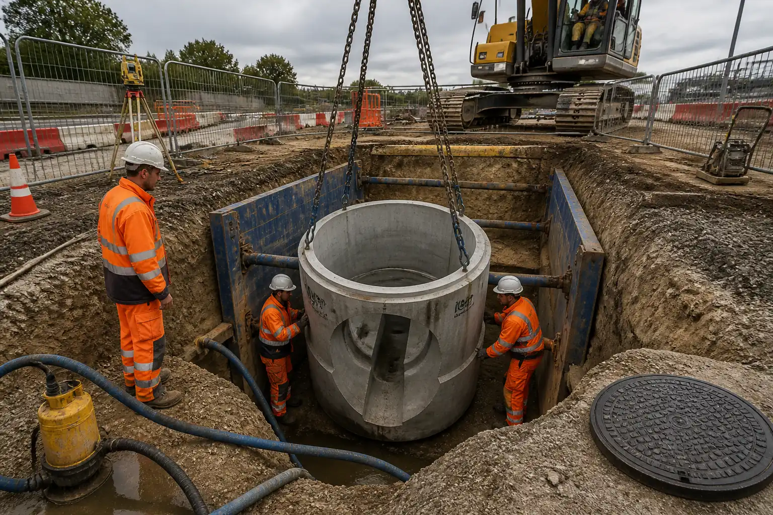

Method Statement: Construction and Installation of External Drainage Manholes, Inspection Chambers, and Gully Traps – Method Statement
AI-assisted method statement with matching ITP, PDF download, and Excel export.
More than a static template
Unlike a downloadable Word or PDF template, this method statement is an AI-assisted editable starting point connected directly to a matching Inspection and Test Plan. Every section is structured, project-adaptable, and ready to export.
- AI-assisted drafting — Customize every section with AI for your specific project scope.
- Linked ITP — A matching inspection and test plan is generated alongside the method statement.
- Multiple export formats — Download as a formatted PDF or editable Excel spreadsheet.
- Editable starting point, not a final document — Review, verify, and adjust all content against your project requirements before use.
Static template vs. Quollnet workflow
| Feature | Static template | Quollnet |
|---|---|---|
| Project-specific content | Manual fill-in required | AI-assisted customization |
| Linked ITP | Separate document, no link | Matching ITP included |
| Export formats | Usually PDF only | PDF and Excel |
| Structured sections | Free-form layout | 13 standardized sections |
| Saved to your account | Local file only | Cloud-saved, reusable |
| Content accuracy | You verify everything | AI-assisted, you still verify |
| Cost | Often free but time-intensive | Free to customize and download |
What you can customize
When you save this method statement to your account, every section becomes editable. The following 13 sections are included:
- Scope — Defines the activity and its boundaries.
- References — Standards, specifications, and drawings.
- Responsibilities — Roles and accountabilities.
- Resources — Labour, plant, and equipment summary.
- Materials — Materials and compliance requirements.
- Equipment — Tools and equipment details.
- Prerequisites — Hold points and pre-conditions.
- Method sequence — Step-by-step construction sequence.
- Safety controls — HSE risk controls and PPE.
- Environmental controls — Environmental mitigation measures.
- QA/QC — Quality inspection and test requirements.
- ITP — Inspection and Test Plan table (has its own page).
- Attachments — Referenced drawings and documentation.
Why this method statement is used
This method statement is used to define and communicate the approved procedure for carrying out method statement: construction and installation of external drainage manholes, inspection chambers, and gully traps on site. It ensures the work is planned in advance, the correct resources and controls are in place, and all personnel understand responsibilities, sequence, quality requirements, and safety controls before work begins. It aligns site execution with the documented scope and acceptance expectations.
Who uses this method statement
This method statement is used by contractors, site supervisors, project engineers, QA/QC engineers, HSE officers, consultants, and client representatives. It serves as a shared reference for planning, execution, supervision, inspection, and approval of the activity on site.
When it is prepared and submitted
The method statement is prepared before the work activity starts and submitted as part of the pre-construction documentation package for review and approval.
Who reviews or approves it
The method statement is usually submitted to the client representative, consultant, resident engineer, or project management consultant for review and approval before the work commences.
Important approval note
This method statement is an AI-assisted editable starting point, not a pre-approved document. Before use on any project, all content must be reviewed and approved by the relevant parties (superintendent, principal contractor, or client representative) in accordance with your contract and project quality plan.
For example: if your specification requires a departure from a referenced standard, that departure must be documented and approved separately — this method statement will not capture that automatically. Always verify against your applicable drawings, specifications, and regulatory requirements.
Method statement content
Scope
Overview
This method statement defines the procedures, quality controls, safety and environmental controls for the construction and installation of external drainage manholes, inspection chambers, and gully traps using precast concrete components. It covers:
- Survey and setting out
- Excavation, ground support, and dewatering
- Sub-base preparation and blinding
- Precast base and ring installation, jointing, sealing, and external waterproofing (if specified)
- Formation of channels and benching
- Pipe connections, rocker pipes, and drop pipe arrangements (internal/external)
- Frame and cover installation and adjustment to final levels
- Backfilling, compaction, and reinstatement
- Watertightness testing, CCTV survey (where specified), and handover documentation
Locations and Extents
- Applicable to all off-road and in-carriageway drainage structures within . Exact chainages and coordinates shall be taken from IFC drawings [Verify per project drawings].
Exclusions
- Deep shaft sinking (>6 m) requiring segmental lining or secant piles
- Pumping station M&E fit-out
- Lining systems beyond basic waterproof coatings unless specified
Objectives
- Install durable, watertight, maintainable drainage access structures to the specified line/level/grade with compliant load-rated frames and covers.
References
| Document Type | Reference / Number | Revision | Notes |
|---|---|---|---|
| BS EN 1610: Construction and testing of drains and sewers | Primary standard for installation and exfiltration/infiltration testing of pipelines and manholes. | ||
| BS EN 752: Drain and sewer systems outside buildings | Functional requirements and system performance. | ||
| BS EN 1917 / BS 5911-3: Concrete manholes and components | Specifications for precast rings, bases, and cover slabs. | ||
| BS EN 124 (EN 124-2): Gully tops and manhole tops for vehicular and pedestrian areas | Load classes (e.g., D400/E600/F900) and installation guidance. | ||
| BS 8500 / EN 206: Concrete specification and production | Concrete grades and durability requirements [Verify per project specification]. | ||
| BS EN 681-1: Elastomeric seals - Requirements for pipe joints | Seals and flexible couplings for watertight joints. | ||
| BS EN 998 (mortar), BS EN 13139 (aggregates for mortar) | Benching/rendering mortars and bedding mortars [Verify class and mix]. | ||
| BS 5975: Temporary works procedures and the permissible stress design of falsework | Temporary works management and excavation support design. | ||
| HSG47 (or local equivalent): Avoiding danger from underground services | Service detection and safe digging [Verify per local regulation]. | ||
| ISO 9001, ISO 14001, ISO 45001 | Management system requirements for quality, environment and OH&S. | ||
| ASTM C1244 (alternative): Vacuum testing of manholes | Alternative test where specified by Client [Verify per project]. |
Responsibilities
| Role | Responsibility | Name / Party |
|---|---|---|
| Project Manager | Project Manager | Contractor |
| Construction Manager | Construction Manager | Contractor |
| Site Engineer | Site Engineer | Contractor |
| HSE Manager | HSE Manager / Officer | Contractor |
| QA/QC Engineer | QA/QC Engineer | Contractor |
| Surveyor | Land Surveyor | Contractor |
| TWC | Temporary Works Coordinator (TWC) | Contractor |
| Lifting Supervisor | Lifting Supervisor / Appointed Person | Contractor |
| Foreman | Foreman | Contractor |
| Engineer | Independent Tester / Client Representative | Engineer |
Resources
| Resource Type | Description | Quantity | Remarks |
|---|---|---|---|
| Labor | 7 persons | ||
| Specialist Labor | 3 persons | [Verify per risk assessment] |
Materials
| Material | Specification / Grade | Quantity | Remarks |
|---|---|---|---|
| Precast concrete manhole rings, bases, cover slabs | BS EN 1917 / BS 5911; concrete class per exposure [Verify]. Joints to be watertight. | As per BOQ | Precast base slab where specified |
| Elastomeric joint seals / butyl sealant strips | EN 681-1 compliant; manufacturer’s installation procedures. | As required | |
| Benching and rendering mortar | High-strength shrinkage-controlled mortar M12 or site mix 1:3 (cement:sand) with waterproofer [Verify]. | As required | |
| Concrete (blinding and structural) | Blinding: C12/15 (50–75 mm). Base/encasement: typically C32/40, S3 slump [Verify]. | As required | |
| Frames and covers (heavy duty) | EN 124 Class D400 for carriageways; E600/F900 where designated [Verify]. Anti-rock, locked if specified. | As required | |
| Rocker pipes, connectors, flexible couplings | Same material/diameter as main; rocker length 0.6 m typical. Flexible coupling EN 681-1. | As required | |
| External waterproofing (if specified) | Bituminous coating or membrane system compatible with concrete [Verify]. | As required | |
| Bedding mortar/resin for frames | High-strength polymer-modified or epoxy mortar; early strength for traffic opening [Verify]. | As required | |
| Granular backfill | Type 1/Type 2 to EN 13242 or selected excavated fill [Verify]. | As required |
Equipment
| Equipment | Capacity / Type | Quantity | Inspection Required |
|---|---|---|---|
| Excavator (13–20 t) with quick hitch | 1 | Daily pre-use; 6-monthly LOLER/PUWER certs [Verify local]. | |
| Excavation support system (shoring/trench box/frames) | Set | TWC inspection and permit to excavate. | |
| Lifting chains/slings/shackles and ring lifting pins | WLL ≥ load | 2 | Color-coded, current certificates. |
| Ring lifter/vacuum lifter | 1 | Operator trained; test certification. | |
| Dewatering pumps with discharge hoses | >20 m head [Verify] | 2 | Backflow/silt control fitted. |
| Pipe laser/auto-level/total station | 1 | Calibration certificates current. | |
| Compaction equipment (rammer/plate/roller) | 2 | Vibration exposure managed. | |
| Concrete mixer/agitator and vibrators | 1 | Electrical RCD checks. | |
| Multi-gas detector (O2, H2S, CO, LEL) | 1 | Bump test/calibration logs. | |
| Confined space entry and rescue set | 1 set | Permit to work; trained team. | |
| CCTV crawler/camera (if specified) | 1 | Operator certified; footage recorded. | |
| Testing equipment for water/air/vacuum | Set | Calibrated gauges; safe anchorage. |
Prerequisites
- Approved IFC drawings, method statement, risk assessments, and ITPs.
- Material approvals: precast rings/bases/cover slabs, joint seals, frames and covers, mortars, concrete mix designs.
- Utility detection completed (records from GPR/CAT and trial holes). Marked services and permit to excavate issued.
- Temporary works design for excavation support, lifting plans, and dewatering strategy approved by TWC.
- Traffic management plan and road opening permit where in carriageway.
- Confined space risk assessment, rescue plan, permit-to-work, and trained personnel available.
- Calibrations: survey equipment, gas detectors, pressure gauges for testing.
- Weather and groundwater assessment completed; contingency for pumping and rain events.
- Pre-start briefing and TBT conducted; exclusion zones and signage installed.
- Adjacent structures and utilities protection measures in place (support/protection slabs as required).
Method Sequence
| Step | Activity | Description | Responsibility | Inspection / Hold Point |
|---|---|---|---|---|
| 1 | Setting out and pre-lift checks | Establish line/level and chainage using control points. Mark manhole center and pipe inverts. Confirm lift plan, capacities, and tag lines. | Surveyor / Lifting Supervisor | Check setting-out records and lifting gear certificates. |
| 2 | Excavation and support | Excavate to formation allowing for working room and shoring. Install trench box/shoring per TWC design. Maintain safe batter if unsupported. | Construction Manager / Foreman | Permit to excavate; TWC inspection of support. |
| 3 | Dewatering and formation preparation | Install sump and pumps. Trim formation; no soft spots. Replace unsuitable material with compacted granular fill. Place 50–75 mm blinding C12/15. | Foreman | Check formation CBR/firmness; verify blinding thickness. |
| 4 | Base placement (precast or in-situ) | Lift precast base into position on blinding; check level. For in-situ, place base concrete to thickness [Verify], vibrate and finish level. | Lifting Supervisor / Site Engineer | Level/grade check; reinforcement (if any) prior to pour. |
| 5 | Ring installation and jointing | Install first ring on base. Clean and apply elastomeric/butyl joint. Lower subsequent rings using certified lifting eyes. Align and plumb. | Foreman / Site Engineer | Joint cleanliness and seal continuity. |
| 6 | Pipe openings and connections | Core drill or use preformed holes. Fit rocker pipes and flexible connectors. Maintain pipe invert and gradient per design. | Foreman / Site Engineer | Check hole location/invert; connector seating. |
| 7 | Drop pipe arrangement (if required) | Provide internal or external drop where incoming invert difference >0.6 m [Verify]. Fix drop pipe with brackets; encase external drops in C32/40; provide rodding access. | Site Engineer / Foreman | Check bracket fixings and encasement dimensions. |
| 8 | Benching and channel formation | Form U-shaped channel to match pipe diameter; smooth steel-trowel finish. Bench to fall 1:10 to 1:12 toward channel; radiused junctions. | Foreman | Visual and dimension check. |
| 9 | Chamber height adjustment and cover slab | Install reducer/cover slab. Build up with precast adjusting rings or engineering bricks (limited courses) as specified. Prepare frame bedding. | Foreman | Check material type and number of courses. |
| 10 | Frame and cover installation | Set frame to finished surface level using high-strength bedding/resin mortar. Align to road camber; anti-rock check; lock if specified. | Foreman / Site Engineer | Level and seating of frame; mortar cure. |
| 11 | External waterproofing (if specified) | Apply coating or wrap to clean dry concrete surfaces per manufacturer’s instructions. | Foreman | DFT and coverage checks (if applicable). |
| 12 | Backfilling and compaction | Place selected granular backfill in 150–250 mm layers; compact to specified density. Protect structures and pipes during compaction. | Foreman | Layer thickness and compaction checks. |
| 13 | Watertightness testing | Test manholes after curing of mortars. Water test to EN 1610 (exfiltration) to required head; alternative vacuum test ASTM C1244 if specified. | QA/QC Engineer / Testing Technician | Witness by Engineer. |
| 14 | CCTV survey (if required) | Survey connected pipelines and manhole internals to confirm alignment, joints, and cleanliness. | Specialist Subcontractor | Engineer review of footage. |
| 15 | Surface reinstatement and demobilization | Reinstate pavement or landscaping per specification. Remove shoring after backfill reaches safe level. Clear site and update as-builts. | Construction Manager / Foreman | Final inspection with Engineer. |
Health, Safety, and Environment (HSE) - Safety Controls
Task-specific hazards and controls
- Hazard: Excavation collapse
- Likely consequence: Burial, crush injuries, fatality
- Engineering/procedural control: Temporary works design by competent person; install shoring/trench boxes before entry; keep surcharge loads (spoil, plant) ≥1 m from edge; inspect excavations at start of shift and after rain
- Required PPE: Helmet with chin strap, boots with steel toe/midsole, gloves, high-vis, eye protection
- Collective preventive measure: Edge protection, barriers, access ladders at ≤6 m spacing
-
Inspection/permit/supervision: TWC inspections; Permit to excavate; daily excavation checklist [Verify per project HSE plan and local regulations]
-
Hazard: Underground utility strike
- Likely consequence: Electrocution, explosion, flooding, service outage
- Engineering/procedural control: Review utility records; GPR/CAT scan and mark-out; hand dig trial holes; exclusion zones around known utilities
- Required PPE: Dielectric gloves (if required), arc-rated clothing near HV, eye protection
- Collective preventive measure: Supervised hand-digging; insulated tools
-
Inspection/permit/supervision: Permit to dig; HSG47/local equivalent compliance
-
Hazard: Lifting of precast units
- Likely consequence: Crushing, dropped loads, rigging failure
- Engineering/procedural control: Appointed Person lift plan; certified lifting points and gear; tag lines; exclusion zone; competent operator and banksman; no personnel under suspended loads
- Required PPE: Helmet with chin strap, gloves, boots, high-vis, eye/hand protection
- Collective preventive measure: Physical barriers and banksman control
-
Inspection/permit/supervision: Pre-lift inspection; current LOLER/PUWER certs; lift permit
-
Hazard: Confined space entry (manholes)
- Likely consequence: Asphyxiation, H2S exposure, entrapment
- Engineering/procedural control: Avoid entry where possible; otherwise, permit-controlled entry; pre-entry and continuous gas monitoring (O2, H2S, CO, LEL); forced ventilation; intrinsically safe lighting; retrieval system (tripod/winch); trained rescue team on standby
- Required PPE: Harness with rescue attachment, gas detector, gloves, helmet, boots, eye protection; respirator only if specified by assessment
- Collective preventive measure: Barriers and attendants at top manhole; signage and lock-off
-
Inspection/permit/supervision: Confined space permit; calibration/bump-test records; rescue drill verification
-
Hazard: Working in/near traffic
- Likely consequence: Vehicle impact injuries
- Engineering/procedural control: Traffic management plan; lane closures; signage per road authority manual; attenuator where required
- Required PPE: High-vis class 3, helmet, boots
- Collective preventive measure: Temporary barriers, cones, lighting
-
Inspection/permit/supervision: Road opening permit; traffic management inspections
-
Hazard: Cement/concrete skin contact and silica dust
- Likely consequence: Chemical burns, dermatitis, respiratory irritation
- Engineering/procedural control: Use pre-mixed mortar where possible; wet cutting with suppression; wash stations; avoid dry sweeping
- Required PPE: Alkali-resistant gloves, long sleeves, eye/face protection, FFP3/N95 respirator for dusty tasks
- Collective preventive measure: Dust suppression and vacuum extraction tools
-
Inspection/permit/supervision: COSHH/SDS available; task-specific training
-
Hazard: Noise and vibration from compaction
- Likely consequence: Hearing loss, HAVS
- Engineering/procedural control: Select low-vibration tools; limit trigger time; rotate tasks
- Required PPE: Hearing protection (SNR matched to exposure), anti-vibration gloves as comfort aid
- Collective preventive measure: Barriers and signage
-
Inspection/permit/supervision: HAV/Noise exposure logs; equipment maintenance
-
Hazard: Water ingress and dewatering discharge
- Likely consequence: Slips, erosion, contamination
- Engineering/procedural control: Sump management; secure hoses; silt bags/sedimentation tanks
- Required PPE: Waterproof boots, gloves
- Collective preventive measure: Hose ramps and bunds
-
Inspection/permit/supervision: Environmental permit/approval for discharge where applicable
-
Hazard: Manual handling of rings, frames, and stoppers
- Likely consequence: Musculoskeletal injury, crush points
- Engineering/procedural control: Use mechanical aids; team lifting; pinch-point awareness
- Required PPE: Gloves, safety boots
- Collective preventive measure: Handling aids on site
-
Inspection/permit/supervision: Manual handling training verification
-
Hazard: Entry of unauthorized persons into open manholes
- Likely consequence: Falls from height, drowning
- Engineering/procedural control: Temporary covers/grills; barriers and signage; never leave openings unattended
- Required PPE: N/A for public; site PPE for workers
- Collective preventive measure: Locked covers outside working hours
- Inspection/permit/supervision: Supervisor checks; security patrols
Environmental Controls
- Silt and sediment control: Install silt fences, dewatering filter bags, or settlement tanks; keep discharge clear of watercourses unless permitted; inspect after rain.
- Spoil management: Segregate contaminated/unsuitable material; stockpile on impermeable base with berms; dispose via licensed carriers with waste transfer notes.
- Noise and vibration: Comply with permitted working hours; use maintained equipment and acoustic shrouds; monitor where near receptors.
- Dust control: Water suppression for cutting/excavation; cover loads; wheel-wash where required; no dry sweeping.
- Concrete and grout washout: Provide lined, contained washout areas; collect and dispose per local regulation.
- Fuel and chemical storage: Bunded containers (110% capacity); spill kits at pumps and refueling points; emergency spill response trained.
- Ecology and groundwater: Prevent grout/mortar ingress to drains; plug pipes during works; avoid contamination; use drip trays.
- Materials efficiency: Order to measured take-off; reuse suitable excavated materials where allowed by specification.
- Carbon considerations: Prefer local precast suppliers; consolidate deliveries; plan just-in-time to minimize idle plant.
- Compliance: Maintain environmental permits/approvals; keep daily environmental inspection logs.
Quality Assurance and Quality Control (QA/QC)
Controls and tolerances
- Line and level: Invert level ±10 mm; cover level tolerances per method step 10.
- Verticality: Chamber plumb within 1:400; ring joint step ≤10 mm.
- Benching: Smooth finish; bench fall 1:10 to 1:12; no laitance, voids, or ponding.
- Pipe connections: Rocker pipes used; flexible connector seated; gradient within −0/+0.1% of design [Verify].
- Materials: Certificates of conformity for precast components (BS EN 1917/BS 5911), EN 124 covers, EN 681-1 seals. Mortar and concrete batch tickets.
- Compaction: Backfill density ≥95% MDD (landscaped) or ≥98% MDD (carriageway) [Verify]; layer thickness 150–250 mm.
- Testing: Concrete slump and compressive strength; watertightness per BS EN 1610 (or ASTM C1244 vacuum if specified); CCTV where required.
- Protection: Frames locked or secured until opening to traffic; no traffic until bedding mortar achieves minimum strength [Verify manufacturer data].
Documentation
- Inspection requests (IRs), checklists, pour cards, cube reports, calibration records, test certificates, material delivery tickets, as-built surveys (coordinates, inverts), photos, NCR/SN and close-out records.
Hold/Witness Points
- Hold: Excavation support in place; base pre-pour; frame and cover set; watertightness testing; backfill prior to reinstatement.
- Witness: Ring jointing; pipe connections; benching/channeling; drop pipe arrangement.
Attachments
- Approved IFC drawings for drainage layouts and details.
- Temporary works calculations/drawings for excavation support.
- Lift plans and rigging certificates.
- Product data sheets and certificates: precast rings/bases/slabs (EN 1917/BS 5911), EN 124 frames and covers, EN 681-1 seals, mortars, concrete mix designs.
- HSE documentation: RAMS, permits (excavation, lifting, confined space), utility scan reports, TBT records.
- Test formats: concrete test sheets, compaction test sheets, watertightness test certificates, CCTV templates.
- Checklists: excavation, ring jointing, frame/cover seating, backfilling, reinstatement.
- As-built survey template and example.
This content is a read-only public reference. Download or customize to get an editable version.
ITP preview
The first inspection activities from the linked ITP for Method Statement: Construction and Installation of External Drainage Manholes, Inspection Chambers, and Gully Traps:
| Activity | Inspection / Test | Acceptance Criteria | Responsibility | Record |
|---|---|---|---|---|
| Pre-start approvals | Verify approvals: MS/ITP, drawings, permits, material submittals | All approvals in place and current | PM/QA-QC/Engineer | Approval register / permits |
| Survey and setting out | Check coordinates, levels, benchmarks; instrument calibration | Within specified tolerances (±10 mm plan, ±5 mm level) | Surveyor/Site Engineer | Survey report; calibration certs |
| Excavation and support | Excavation dimensions; shoring compliance; permit to dig | Stable excavation; support per design; exclusion zones in place | Construction Manager/TWC/Engineer | Excavation checklist; permit; photos |
Showing 3 of 15 inspection activities. View full ITP →
Related Inspection and Test Plan
An Inspection and Test Plan (ITP) is available for Method Statement: Construction and Installation of External Drainage Manholes, Inspection Chambers, and Gully Traps. The ITP defines the inspection activities, acceptance criteria, hold and witness points, responsible parties, and records required to verify the work described in this method statement.
View the Method Statement: Construction and Installation of External Drainage Manholes, Inspection Chambers, and Gully Traps ITP →