
Method Statement: Precast Segmental Bridge Erection with Match-Cast Epoxy Joints, Temporary and Permanent Post-Tensioning, and Survey Geometry Control – Method Statement
AI-assisted method statement with matching ITP, PDF download, and Excel export.
More than a static template
Unlike a downloadable Word or PDF template, this method statement is an AI-assisted editable starting point connected directly to a matching Inspection and Test Plan. Every section is structured, project-adaptable, and ready to export.
- AI-assisted drafting — Customize every section with AI for your specific project scope.
- Linked ITP — A matching inspection and test plan is generated alongside the method statement.
- Multiple export formats — Download as a formatted PDF or editable Excel spreadsheet.
- Editable starting point, not a final document — Review, verify, and adjust all content against your project requirements before use.
Static template vs. Quollnet workflow
| Feature | Static template | Quollnet |
|---|---|---|
| Project-specific content | Manual fill-in required | AI-assisted customization |
| Linked ITP | Separate document, no link | Matching ITP included |
| Export formats | Usually PDF only | PDF and Excel |
| Structured sections | Free-form layout | 13 standardized sections |
| Saved to your account | Local file only | Cloud-saved, reusable |
| Content accuracy | You verify everything | AI-assisted, you still verify |
| Cost | Often free but time-intensive | Free to customize and download |
What you can customize
When you save this method statement to your account, every section becomes editable. The following 13 sections are included:
- Scope — Defines the activity and its boundaries.
- References — Standards, specifications, and drawings.
- Responsibilities — Roles and accountabilities.
- Resources — Labour, plant, and equipment summary.
- Materials — Materials and compliance requirements.
- Equipment — Tools and equipment details.
- Prerequisites — Hold points and pre-conditions.
- Method sequence — Step-by-step construction sequence.
- Safety controls — HSE risk controls and PPE.
- Environmental controls — Environmental mitigation measures.
- QA/QC — Quality inspection and test requirements.
- ITP — Inspection and Test Plan table (has its own page).
- Attachments — Referenced drawings and documentation.
Why this method statement is used
This method statement is used to define and communicate the approved procedure for carrying out method statement: precast segmental bridge erection with match-cast epoxy joints, temporary and permanent post-tensioning, and survey geometry control on site. It ensures the work is planned in advance, the correct resources and controls are in place, and all personnel understand responsibilities, sequence, quality requirements, and safety controls before work begins. It aligns site execution with the documented scope and acceptance expectations.
Who uses this method statement
This method statement is used by contractors, site supervisors, project engineers, QA/QC engineers, HSE officers, consultants, and client representatives. It serves as a shared reference for planning, execution, supervision, inspection, and approval of the activity on site.
When it is prepared and submitted
The method statement is prepared before the work activity starts and submitted as part of the pre-construction documentation package for review and approval.
Who reviews or approves it
The method statement is usually submitted to the client representative, consultant, resident engineer, or project management consultant for review and approval before the work commences.
Important approval note
This method statement is an AI-assisted editable starting point, not a pre-approved document. Before use on any project, all content must be reviewed and approved by the relevant parties (superintendent, principal contractor, or client representative) in accordance with your contract and project quality plan.
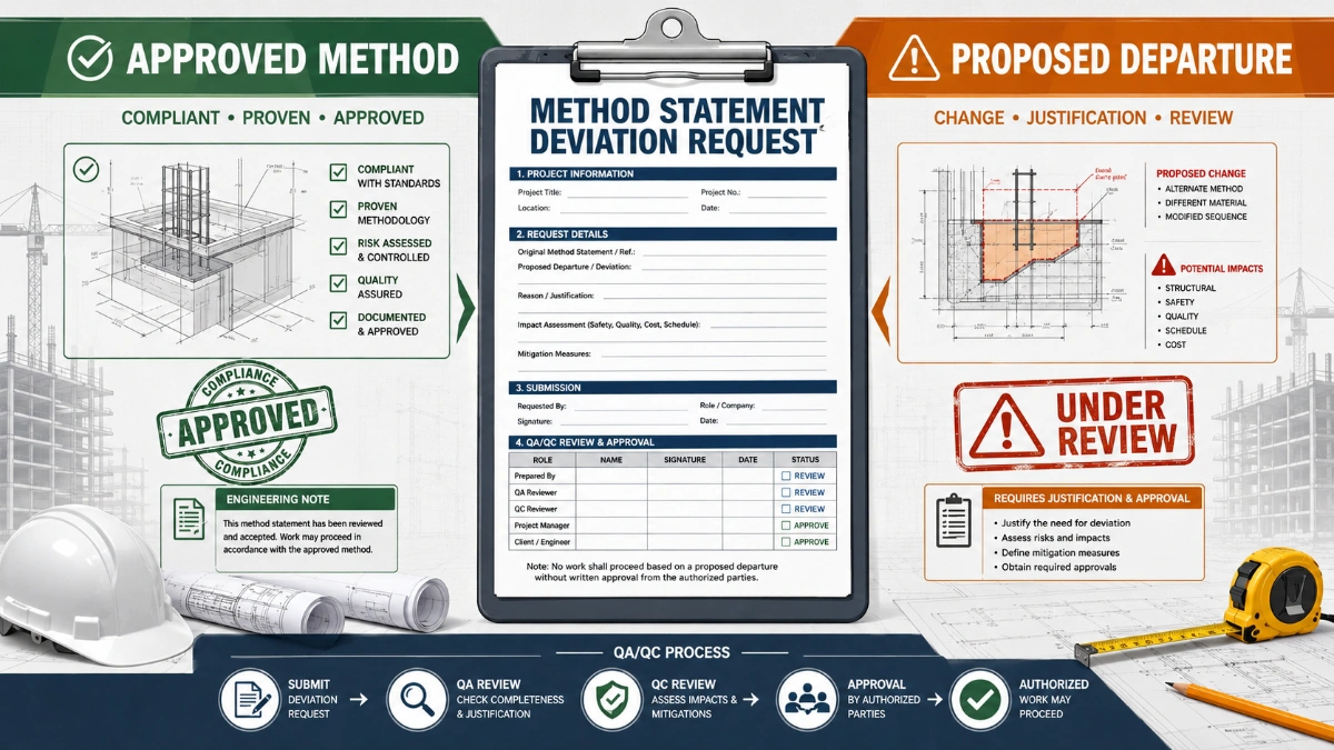
For example: if your specification requires a departure from a referenced standard, that departure must be documented and approved separately — this method statement will not capture that automatically. Always verify against your applicable drawings, specifications, and regulatory requirements.
Method statement content
Scope
Overview
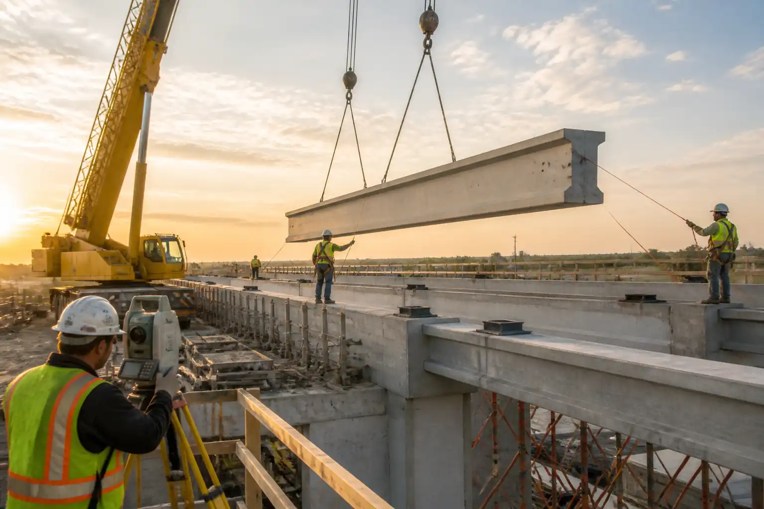
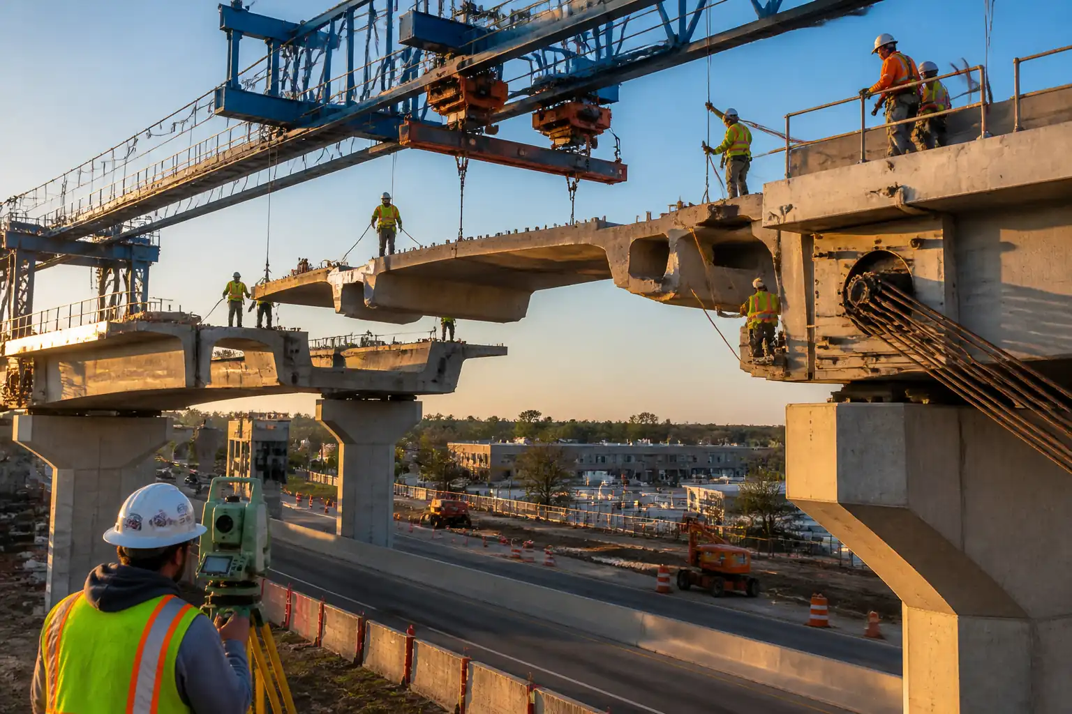
This method statement covers the erection of precast segmental bridge superstructure using a launching gantry/overhead traveler (balanced cantilever or span-by-span), with match-cast epoxy joints, temporary post-tensioning (PT) for segment stabilization and geometry control, installation and stressing of permanent PT tendons, and grouting. It includes survey-based geometry control, QA/QC processes with defined hold/witness points, and HSE/environmental controls.
Inclusions
- Pre-erection checks, approvals, and calibration
- Erection of segments from pier table or previously erected cantilever
- Joint surface preparation and epoxy application at match-cast faces
- Temporary PT installation and stressing to seat joints
- Survey geometry control and camber/alignment verification
- Installation, stressing, and grouting of permanent PT tendons
- Integration of closure/knot segments and continuity tendons
- Documentation, redlines, and as-built survey
Exclusions
- Fabrication of precast segments (covered under separate method)
- Substructure works (piers, foundations) and permanent bearings installation except for interface checks
Typical Tolerances [Verify per project specifications]
- Segment joint epoxy thickness: 1–2 mm (uniform), max local variation ±0.5 mm
- Joint step (flushness): ≤1 mm
- Residual joint gap after temporary PT: ≤0.5 mm (no through-gaps)
- Horizontal alignment at deck edges: ±5 mm
- Vertical camber at control points vs geometry control sheets: ±5 mm per segment; cumulative per span per approved geometry report
- Bearing line and elevation at pier table: ±2 mm
- Temporary/PT jack elongation vs theoretical: within ±5% (unless system-specific)
- Permanent tendon stressing: elongation within ±5% of theoretical; final anchor set within manufacturer’s limits
- Grout properties per EN 447/EN 445: bleed ≤0.5%, fluidity/flow per mix design, density 1.90–2.10 g/ml, chloride ≤0.1% of cement mass
Weather/Operational Constraints [Verify per project specifications]
- Max wind for segment lift/placement: ≤10 m/s sustained, ≤15 m/s gusts
- Epoxy application temperature: 10–35°C; substrate moisture: surface-dry with no free water
- Grouting temperature: 10–30°C; avoid direct solar heating on ducts
- Night works permitted subject to approved lighting and noise controls
Hold Points (typical)
- H1: Launching gantry certification and pre-lift checks
- H2: Joint face inspection & epoxy approval before mating
- H3: Segment alignment/geometry check before temporary PT lock-off
- H4: Survey verification of camber/line before proceeding to next segment
- H5: Permanent PT installation readiness (duct/wedge/anchor inspection)
- H6: Permanent PT stressing (start) and acceptance of forces/elongations
- H7: Tendon grouting (mix, flow/bleed test) and post-grout verification
- H8: Closure segment fit-up and final geometry acceptance
All values and limits noted above must be verified and supplemented by the Issued for Construction (IFC) drawings, approved geometry control report, PT system approvals, and project specifications.
References
| Document Type | Reference / Number | Revision | Notes |
|---|---|---|---|
| Code/Guidance | EN 1992; fib Bulletins 44/48/65 [Verify] | ||
| Standard | EN 13670 | ||
| Standard | ASTM C881/C881M (Type I/II/IV, Grade 2 or 3 as applicable) | Manufacturer’s data sheet governs mix ratio and pot life | |
| Standard/Approval Guideline | EN 10138 (Strands) [or ASTM A416]; EAD 160004-00-0301 (formerly ETAG 013) for PT kits | Use approved PT system with ETA or equivalent | |
| Standards | EN 445, EN 446, EN 447 (Grouting of tendons) [or PTI M50 as alternative] | Select one framework per project QA | |
| Standards | ISO 17123 series (Field procedures for surveying instruments) | ||
| Standards/Guidance | ISO 9927 (Cranes—inspections); ISO 12480 (Cranes—safe use) [Verify local regulations] | Appointed Person plan required | |
| Standard | ISO 9001 (Quality Management Systems) |
Responsibilities
| Role | Responsibility | Name / Party |
|---|---|---|
| PM | Authorizes method and ITP; ensures contract compliance | Contractor |
| CM | Implements sequence, coordinates trades, ensures HSE controls | Contractor |
| Superintendent | Pre-lift checks, rigging, positioning, temporary PT application | Contractor |
| Survey | Sets control points; monitors line/level/camber; issues geometry reports | Contractor |
| PT Supervisor | Confirms tendon components, jacking sequence, elongations, grout QA | Specialist Subcontractor |
| QA/QC | Verifies inspections/tests, manages IRs, NCR/CAR, calibrations | Contractor |
| HSE | Task-specific risk assessments, permits, monitoring, incident response | Contractor |
| Lifting | Rigging plan, WLL compliance, exclusion zones | Contractor |
| TPI/Engineer | Witness/hold point inspections per ITP | Engineer/Employer |
Resources
| Resource Type | Description | Quantity | Remarks |
|---|---|---|---|
| Labour | Gantry operator(s), riggers, signalers | 8–12 | |
| Labour | Lead surveyor + assistant(s) | 2–3 | |
| Labour | Certified PT technicians | 4–8 | |
| Staff | QA/QC engineer, inspectors, HSE officer | 3–5 |
Materials
| Material | Specification / Grade | Quantity | Remarks |
|---|---|---|---|
| Concrete segments | EN 206 for concrete; project specs | ||
| Epoxy | Type I/II/IV, Grade 2 or 3 [Verify] | ||
| Strand/Bar | Diameter and grade per design | ||
| PT kit | Per approved PT system | ||
| PT grout | Prepackaged PT grout [Verify] | ||
| Shims | Steel/HDPE as specified |
Equipment
| Equipment | Capacity / Type | Quantity | Inspection Required |
|---|---|---|---|
| Gantry | As per design | 1 | Yes |
| Lifting gear | WLL ≥ 1.5 × load [Verify] | As required | Yes |
| Jacks | Per tendon design | Set | Yes |
| Grout plant | Output 30–60 L/min [Verify] | 1–2 sets | Yes |
| Survey kit | Sets as needed | Yes | |
| Epoxy tools | Sets | Yes | |
| Access | As required | Yes |
Prerequisites
- Approved IFC drawings, erection sequence, and geometry control report.
- Approved method statement and ITP; task-specific risk assessments and lifting plan signed by Appointed Person.
- Launching gantry erected, aligned, commissioned, and load-tested; certificates available. Emergency procedures briefed.
- PT system approvals (ETA/EAD or equivalent), stressing and grouting procedures approved.
- Calibrations current for jacks, gauges, load cells, survey instruments (≤6 months or per spec).
- Precast segments accepted: dimensional check, duct integrity, lifting inserts inspected, identification and orientation confirmed.
- Environmental conditions within limits: wind, temperature, rain; lighting suitable for night works if applicable.
- Exclusion zones and traffic management in place under erection front; permits obtained [Verify per project HSE plan and local regulations].
- Materials on hand: epoxy (sufficient batches), grout, wedges, vents, couplers, consumables; SDS available.
- Crew briefed via toolbox talk on sequence, hazards, communication signals, and emergency response.
- Utilities/services clearance for any ground-based crane operations and power feeds for gantry/HPU.
- QA hold/witness points communicated to Engineer/Third Party with 24–48 h notice [Verify].
Method Sequence
| Step | Activity | Description | Responsibility | Inspection / Hold Point |
|---|---|---|---|---|
| 1 | Pre-erection setup and survey control | Establish/verify control points on piers/abutments; install targets on gantry and pier tables; check gantry alignment and rail level | Survey Manager; Erection Superintendent | Closure checks and level differences |
| 2 | Segment receipt and pre-lift inspection | Confirm segment ID, orientation, lifting points, duct continuity and cleanliness, embedded items | QA/QC; Erection Superintendent | Visual and dimensional check; duct probe |
| 3 | Rigging and lift to gantry | Connect lifting frames/strand jacks; lift clear; travel to position maintaining exclusion zone | Lift Supervisor; Gantry Operator | Pre-lift checklist; wind speed check |
| 4 | Joint surface preparation | Dry-fit check; clean with oil-free air; remove laitance; ensure surface-dry; trial contact of shear keys | Erection Crew; QA/QC | Surface condition, dryness test |
| 5 | Epoxy mixing and application | Mix components to manufacturer ratio; apply uniform coat to both faces using serrated trowel/roller to 1–2 mm; avoid entrapped air | Erection Crew; QA/QC | Batch ID; pot life; coverage |
| 6 | Segment mating and alignment | Bring segment into contact; engage shear keys; use alignment pins/jacks to achieve line/level and twist | Gantry Operator; Surveyor | Real-time survey at predefined control points |
| 7 | Temporary PT installation and stressing | Install temporary bars/strands and anchor nuts; stress in symmetric pattern to seat joint; lock off | PT Supervisor | Gauge and elongation monitoring |
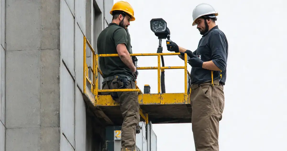
| 8 | Geometry verification and camber control | Survey after temp PT lock-off; update geometry control model; apply fine adjustments with gantry jacks if required | Survey Manager | Check line, level, camber at control points |
| 9 | Repeat erection cycle | Proceed with next segments following Steps 2–8, maintaining symmetric progression in balanced cantilever | Erection Superintendent | As above |
| 10 | Closure/key segment fit-up | Dry-fit closure; check geometry; finalize epoxy and temporary PT to close the gap as per designed closure forces | PT Supervisor; Survey Manager | Survey checks; joint condition |
| 11 | Permanent PT installation | Thread strands; install anchorages, trumpets, burst reinf. checks; lube/grease for external tendons if applicable; verify vents/inlets | PT Supervisor | Component check; duct continuity; vent positions |
| 12 | Permanent PT stressing | Stress per approved sequence/load steps; monitor force and elongation; record anchor set; install anchor caps | PT Supervisor; QA/QC | Witness by Engineer/TPI as required |
| 13 | Tendon grouting | Prepare grout; perform pre-grout tests; grout from low to high end until clean consistency at vents; close vents sequentially; monitor pressure | PT Supervisor; Materials Eng. | Grout tests (flow, density, bleed), temperature |
| 14 | Removal/retension of temporary PT | After sufficient permanent PT and stability confirmed, remove or retension temporary bars as designed | PT Supervisor; Designer approval | Check for movement post-removal |
| 15 | Final survey and as-built | Full survey of span/cantilever; compile records; punch-list closeout | Survey Manager; QA/QC | As-built vs design |
Safety Controls
Task-Specific Hazards and Controls
1) Hazard: Working at height on launching gantry and segment edges
- Likely consequence: Falls leading to serious injury or fatality
- Engineering/procedural control: Install full edge protection (guardrails/toeboards), certified lifelines; use MEWPs for access; maintain tidy decks; mandatory 100% tie-off when outside protected zones
- Required PPE: Full-body harness with double lanyard or SRL, helmet with chin strap, cut-resistant gloves, safety boots
- Collective preventive measure: Guardrails, netting beneath work fronts where feasible
- Inspection/permit/supervision: Daily access and fall protection inspections; Work at Height permit; supervision by trained line manager [Verify per project HSE plan and local regulations]
2) Hazard: Suspended loads during segment lifting and gantry travel
- Likely consequence: Crush/strike injuries, fatality, dropped objects
- Engineering/procedural control: Exclusion zones with barriers and spotters; taglines to control sway; lift only within wind thresholds; no personnel under load; certified lifting points and gear
- Required PPE: Helmet with chin strap, hi-vis, gloves, safety boots
- Collective preventive measure: Physical barriers and signage under the lift path
- Inspection/permit/supervision: Appointed Person lift plan; pre-lift checklist; lifting gear inspection and color-coding; anemometer monitoring
3) Hazard: Gantry instability or derailment
- Likely consequence: Catastrophic collapse, multiple injuries
- Engineering/procedural control: Pre-shift checks on rails/clamps/power; implement emergency stops and limit switches; do not travel under excessive wind; balanced loading
- Required PPE: As standard; rescue equipment available
- Collective preventive measure: Secondary restraints; wind alarms
- Inspection/permit/supervision: Commissioning certificate; daily function tests; periodic third-party inspections
4) Hazard: Post-tensioning stressing (stored energy)
- Likely consequence: Jack/strand failure, projectile hazards
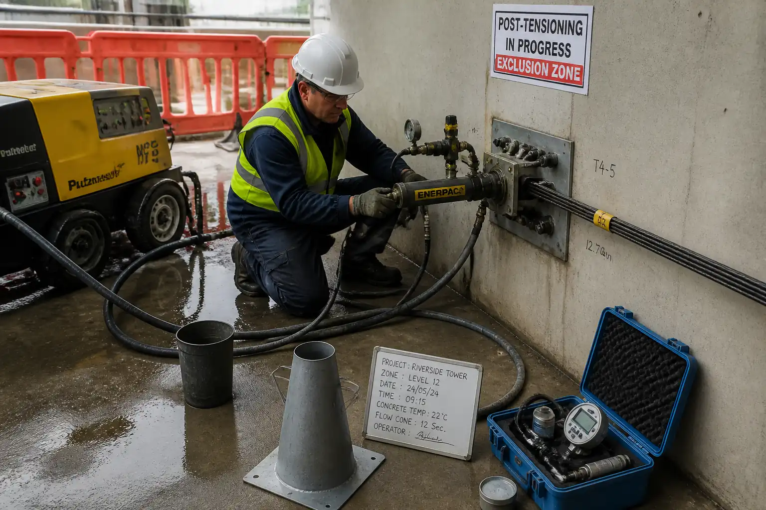
- Engineering/procedural control: Exclusion zone behind jack; use deflection shields; verify calibration; adhere to staged loading; monitor elongations and anchor seating
- Required PPE: Eye/face protection, gloves, hearing protection, safety boots, helmet
- Collective preventive measure: Barriers around stressing end; remote gauges where possible
- Inspection/permit/supervision: PT permit-to-stress; certified PT technicians; supervision by PT Supervisor; equipment calibration records
5) Hazard: Epoxy exposure (chemical)
- Likely consequence: Dermatitis, respiratory irritation
- Engineering/procedural control: Use low-VOC products where possible; mixing in ventilated area; avoid skin contact; spill kits ready
- Required PPE: Chemical-resistant gloves, goggles/face shield, coveralls, respirator if required by SDS
- Collective preventive measure: Local extraction/ventilation at mixing station
- Inspection/permit/supervision: SDS review; COSHH/chemical permit; first-aid eyewash availability
6) Hazard: Noise and vibration from equipment and stressing
- Likely consequence: Hearing damage, hand-arm vibration
- Engineering/procedural control: Limit exposure duration; maintain tools; schedule high-noise tasks daytime
- Required PPE: Hearing protection
- Collective preventive measure: Acoustic screens where practicable
- Inspection/permit/supervision: Noise surveys; HAVS monitoring program
7) Hazard: Night works/poor visibility
- Likely consequence: Trips, miscommunication, rigging errors
- Engineering/procedural control: Illumination ≥150 lux at workface; radios with agreed signals; reflective PPE
- Required PPE: Hi-vis with retroreflective strips
- Collective preventive measure: Fixed lighting towers; emergency lighting
- Inspection/permit/supervision: Night-work permit; supervisor presence and shift handovers
8) Hazard: Manual handling of wedges, ducts, and tools
- Likely consequence: Strains and sprains
- Engineering/procedural control: Use mechanical aids; team lifts; job rotation
- Required PPE: Gloves, supportive footwear
- Collective preventive measure: Material hoists and tool tethers
- Inspection/permit/supervision: Manual handling training; dropped object prevention checks
9) Hazard: Hot surfaces/hydraulic leaks on HPU/gantry
- Likely consequence: Burns, slips, fire
- Engineering/procedural control: Fit drip trays; use fire-resistant hoses; routine leak checks; maintain housekeeping
- Required PPE: Gloves, eye protection
- Collective preventive measure: Spill containment and fire extinguishers (Class B)
- Inspection/permit/supervision: Equipment inspection logs; hot-work permit if any hot cutting is required
10) Hazard: Weather (high winds, rain on epoxy, lightning)
- Likely consequence: Loss of control, poor bond, electrical hazards
- Engineering/procedural control: Stop lifts beyond thresholds; cover joints; lightning watch and cease elevated works during storms
- Required PPE: Weather-appropriate PPE, dielectric gloves if necessary
- Collective preventive measure: Weather monitoring station
- Inspection/permit/supervision: Supervisor authority to stop work; documented thresholds and actions
Note: All permits and controls shall be verified per project HSE plan and local regulations.
Environmental Controls
- Epoxy and chemical management: Store in bunded areas; use spill trays during mixing; provide spill kits (absorbent pads, neutralizers). Dispose of epoxy containers as hazardous waste per SDS and local regulations.
- Grout washout: Designate lined washout pits; do not discharge cementitious wash water to drains/watercourses. Treat and dispose via licensed contractor.
- Noise and working hours: Comply with permitted hours; use acoustic screens and maintain equipment to minimize noise.
- Dust and debris: Keep workfaces clean; cover open ducts; use wet/damp wiping rather than air blasting where feasible to minimize airborne dust.
- Hydraulic oil and lubricants: Secondary containment beneath HPU and gantry parking areas; inspect hoses daily; immediate cleanup of leaks.
- Waste segregation: Separate scrap steel, packing materials, general waste; maintain waste transfer notes.
- Lighting: Direct away from public receptors; avoid glare for road/rail users.
- Wildlife and waterways: If over water, install debris nets and drip trays; prohibit material drops; retrieve any fallen items immediately.
- Energy efficiency: Shut down idling plant when not in use; use LED lighting.
- Emergency response: Environmental incident response plan posted; notify authorities per permit requirements. [Verify per project HSE plan and local regulations].
QA/QC
QA/QC Controls
- Document control: Use latest IFC drawings, approved geometry control sheets, PT procedures, and supplier manuals. Redline field changes and submit as-builts.
- Calibrations: Jacks, gauges, load cells, grout pressure gauges, and survey instruments calibrated within 6 months or per spec; maintain certificates on site.
- Materials traceability: Record segment IDs, epoxy batch/expiry, strand heat numbers, anchorage/wedge lot numbers, grout batch numbers.
- Epoxy QA: Verify storage temperature, batch numbers, mix ratio, pot life, application thickness (1–2 mm) and full coverage. Photograph joint faces pre-mating.
- Geometry control: Survey at each segment addition and after temporary PT lock-off. Maintain cumulative deviation log; implement corrections per geometry plan.
- Temporary PT: Record jack pressures and elongations; verify against theoretical (±5%). Check nuts/locks for seating and mark for movement.
- Permanent PT: Verify tendon profile, anchorage seating, wedge bite, jacking sequence, final force, and elongation (±5%). Record anchor set and lift-off if specified.
- Grouting QA: Pre-grout tests (flow, density, bleed per EN 445/447); monitor temperature; maintain continuous flow with proper vent management; post-grout verification (vent back-check, return grout inspection). Retain test cubes if specified.
- Non-conformance: Issue NCR for deviations beyond tolerance; implement corrective action and Engineer approval before proceeding.
- Hold/Witness notifications: Provide timely notifications per ITP; no works to proceed past hold points without signed release.
- Records: Maintain IRs, checklists, survey reports, photos, stressing/grouting logs, material certs, calibration certs, permits, toolbox talks in turnover dossier.
Testing Frequencies [Verify per project specifications]
- Epoxy: One check per batch per shift (mix ratio/gel time/temperature)
- Survey: Each segment addition and at closure; independent check at every 10th segment
- PT: 100% stressing records for all tendons; random independent witness ≥10% of tendons
- Grout: One set of EN 445 tests per grout batch or per tendon run, whichever is more stringent; density/flow every 30 minutes during continuous grouting
- Lift-off tests: As specified by designer (typically sample 5–10% of tendons)
Attachments
- Approved erection drawings and sequence diagrams
- Launching gantry calculations, commissioning, and load test certificates
- Appointed Person lifting plan, rigging drawings, and gear certificates
- PT system approvals (ETA/EAD), stressing and grouting procedures, jack/gauge calibrations
- Geometry control report and camber tables
- Epoxy manufacturer data sheets and Safety Data Sheets (SDS)
- Grout mix design approvals and EN 445/447 test templates
- Risk assessments, permits (Work at Height, Lifting, PT, Night work), toolbox talk records
- Inspection/test forms: joint prep, alignment, stressing, grouting, survey
- Turnover dossier index and as-built drawing register
This content is a read-only public reference. Download or customize to get an editable version.
ITP preview
The first inspection activities from the linked ITP for Method Statement: Precast Segmental Bridge Erection with Match-Cast Epoxy Joints, Temporary and Permanent Post-Tensioning, and Survey Geometry Control:
| Activity | Inspection / Test | Acceptance Criteria | Responsibility | Record |
|---|---|---|---|---|
| Gantry certification and pre-lift setup | Review certificates; pre-use functional tests; rail/level check | All certificates valid; gantry alignment within ±2 mm over support spacing; safety devices operational | Contractor QA/QC; Engineer/TPI (Witness) | IR; pre-lift checklist; certificates copy |
| Segment pre-lift inspection | Visual/dimensional check; duct continuity check | No damage; dimensions within tolerance; ducts clear | QA/QC; Engineer/TPI (Witness) | Segment inspection IR; photos |
| Joint surface prep and epoxy application | Cleanliness/dryness; epoxy batch, pot life, coverage and thickness | Surface clean/dry; epoxy 1–2 mm uniform; full coverage | QA/QC; Engineer (Hold) | IR; epoxy batch log; photos |
Showing 3 of 10 inspection activities. View full ITP →
Related Inspection and Test Plan
An Inspection and Test Plan (ITP) is available for Method Statement: Precast Segmental Bridge Erection with Match-Cast Epoxy Joints, Temporary and Permanent Post-Tensioning, and Survey Geometry Control. The ITP defines the inspection activities, acceptance criteria, hold and witness points, responsible parties, and records required to verify the work described in this method statement.
View the Method Statement: Precast Segmental Bridge Erection with Match-Cast Epoxy Joints, Temporary and Permanent Post-Tensioning, and Survey Geometry Control ITP →Frequently asked questions
Continue with related Quollnet resources connected to this method statement.