
Inspection and Test Plan for Method Statement: Precast Segmental Bridge Erection with Match-Cast Epoxy Joints, Temporary and Permanent Post-Tensioning, and Survey Geometry Control
AI-assisted inspection and test plan connected to a method statement, with PDF and Excel export.
More than a static template
Unlike a downloadable Word or PDF template, this ITP is an AI-assisted editable starting point directly connected to its method statement. Every inspection activity, hold point, and acceptance criterion is structured and ready to adapt to your project.
- AI-assisted customization — Tailor inspection activities and acceptance criteria to your specific project scope.
- Linked method statement — This ITP is connected to the corresponding method statement describing the work sequence.
- Multiple export formats — Download as a formatted PDF or editable Excel spreadsheet.
- Editable starting point, not a final document — Review and verify all content against your project specifications and standards before use.
What you can customize
When you save this ITP to your account, every inspection row becomes editable. You can add, remove, or modify:
- Inspection activity — Description of what is being inspected.
- Inspection type — Hold point (H), Witness point (W), Review (R), or Monitor (M).
- Responsibility — Contractor, subcontractor, engineer, or client.
- Frequency — How often the inspection occurs.
- Acceptance criteria — Referenced standard or specification requirement.
- Records — Forms, test reports, or checklists required as evidence.
Why this ITP is used
To ensure critical phases of segmental erection and PT works are inspected and tested against defined acceptance criteria with clear hold/witness points.
Who uses this inspection and test plan
Contractor QA/QC, PT Supervisor, Survey Team, Engineer’s Representative, and Third-Party Inspectors.
When this ITP is prepared and submitted
Throughout erection: pre-lift, joint prep, alignment, stressing, grouting, closure, and final as-built verification.
Who receives or approves this ITP
The ITP is usually submitted to the client representative, consultant, resident engineer, or project management consultant for review and approval before the related work activity starts.
Inspection scope
Covers gantry certification, segment inspection, joint prep/epoxy, alignment/geometry, temporary PT, permanent PT installation/stressing, and tendon grouting.
Typical hold, witness, and review points
H1 gantry setup, H2 epoxy/joint prep, H3-H4 alignment before lock-off, H5 PT install readiness, H6 stressing, H7 grouting, H8 closure geometry.
Typical inspection records
IRs, survey reports, epoxy logs, stressing records, grout test reports, calibration certificates, photos, and as-built drawings.
Important approval note
This ITP is an AI-assisted editable starting point, not a pre-approved document. Before use on any project, all inspection activities, hold points, and acceptance criteria must be reviewed and approved by the relevant parties (superintendent, principal contractor, or client representative) in accordance with your contract and project quality plan.
Always verify acceptance criteria against your applicable drawings, specifications, and regulatory requirements. Hold points must be confirmed with the relevant authority before work proceeds past that point.
Inspection and test plan
| Activity | Inspection / Test | Acceptance Criteria | Responsibility | Record |
|---|---|---|---|---|
| Gantry certification and pre-lift setup | Review certificates; pre-use functional tests; rail/level check | All certificates valid; gantry alignment within ±2 mm over support spacing; safety devices operational | Contractor QA/QC; Engineer/TPI (Witness) | IR; pre-lift checklist; certificates copy |
| Segment pre-lift inspection | Visual/dimensional check; duct continuity check | No damage; dimensions within tolerance; ducts clear | QA/QC; Engineer/TPI (Witness) | Segment inspection IR; photos |
| Joint surface prep and epoxy application | Cleanliness/dryness; epoxy batch, pot life, coverage and thickness | Surface clean/dry; epoxy 1–2 mm uniform; full coverage | QA/QC; Engineer (Hold) | IR; epoxy batch log; photos |
| Segment alignment before temp PT lock-off | Survey check of step, line, level, twist | Step ≤1 mm; line/level within ±3 mm; twist within ±0.02° [Verify] | Survey; QA/QC; Engineer/TPI (Hold) | Survey report; alignment sheet |
| Temporary PT stressing | Gauge pressure and elongation vs theoretical | Within design force; elongation within ±5%; residual gap ≤0.5 mm | PT Supervisor; QA/QC; Engineer/TPI (Witness) | Temp PT record |
| Permanent PT installation readiness | Anchorage/duct/vent inspection; cleanliness | PT components approved; ducts continuous/clean; vents correctly located | PT Supervisor; QA/QC; Engineer/TPI (Hold) | PT installation checklist |
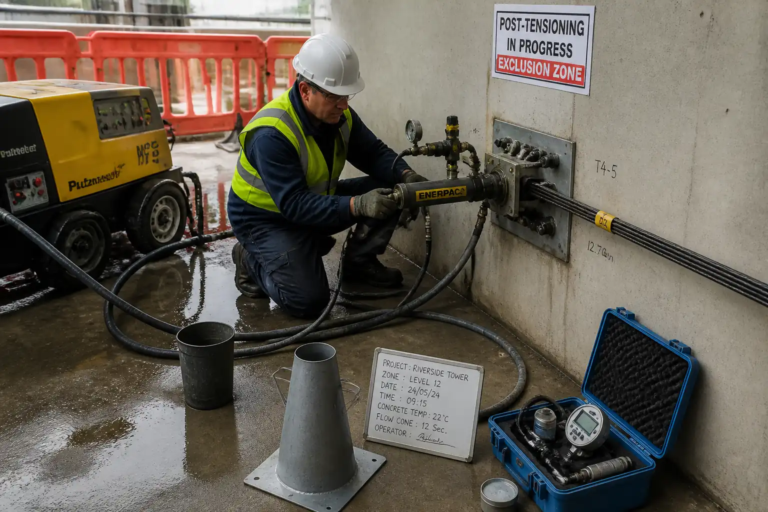
| Permanent PT stressing | Stressing per sequence; force and elongation monitoring; anchor set | Final force per design; elongation within ±5%; acceptable anchor set; no slippage | PT Supervisor; QA/QC; Engineer/TPI (Hold/Witness) | Stressing record; calibration certs |
| Tendon grouting | EN 445 flow/bleed/density; grout temperature; vent management | Bleed ≤0.5%; density 1.90–2.10 g/ml; complete filling at vents; no leaks | PT Supervisor; Materials Engineer; Engineer/TPI (Hold/Witness) | Grouting log; test results |
| Closure segment geometry acceptance | Final gap, line, level, camber | Within project tolerances; joints fully seated | Survey; QA/QC; Engineer/TPI (Hold) | Closure IR; survey report |
| Final as-built survey and documentation | Span/cantilever as-built vs design | Within tolerances; all NCRs closed; records complete | QA/QC; Survey; Engineer/TPI (Witness) | As-built package; IR |
This table is a read-only public reference. Download the PDF or Excel version, or customize this ITP to edit it for your project.
Frequently asked questions
Related method statement
This Inspection and Test Plan is associated with the Method Statement: Precast Segmental Bridge Erection with Match-Cast Epoxy Joints, Temporary and Permanent Post-Tensioning, and Survey Geometry Control method statement, which describes the step-by-step construction sequence, resources, materials, equipment, safety controls, and environmental controls for this activity.
View the Method Statement: Precast Segmental Bridge Erection with Match-Cast Epoxy Joints, Temporary and Permanent Post-Tensioning, and Survey Geometry Control method statement →Continue with related inspection, method statement, article, and checklist resources.