
Method Statement: Installation of Rubber Fender System on Quay Wall (with Underwater Bolt Tightening, QA/QC, and Final Contact Test) – Method Statement
AI-assisted method statement with matching ITP, PDF download, and Excel export.
More than a static template
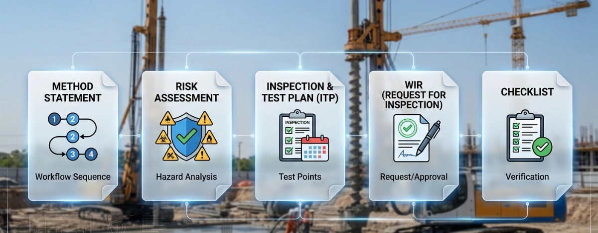
Unlike a downloadable Word or PDF template, this method statement is an AI-assisted editable starting point connected directly to a matching Inspection and Test Plan. Every section is structured, project-adaptable, and ready to export.
- AI-assisted drafting — Customize every section with AI for your specific project scope.
- Linked ITP — A matching inspection and test plan is generated alongside the method statement.
- Multiple export formats — Download as a formatted PDF or editable Excel spreadsheet.
- Editable starting point, not a final document — Review, verify, and adjust all content against your project requirements before use.
Static template vs. Quollnet workflow
| Feature | Static template | Quollnet |
|---|---|---|
| Project-specific content | Manual fill-in required | AI-assisted customization |
| Linked ITP | Separate document, no link | Matching ITP included |
| Export formats | Usually PDF only | PDF and Excel |
| Structured sections | Free-form layout | 13 standardized sections |
| Saved to your account | Local file only | Cloud-saved, reusable |
| Content accuracy | You verify everything | AI-assisted, you still verify |
| Cost | Often free but time-intensive | Free to customize and download |
What you can customize
When you save this method statement to your account, every section becomes editable. The following 13 sections are included:
- Scope — Defines the activity and its boundaries.
- References — Standards, specifications, and drawings.
- Responsibilities — Roles and accountabilities.
- Resources — Labour, plant, and equipment summary.
- Materials — Materials and compliance requirements.
- Equipment — Tools and equipment details.
- Prerequisites — Hold points and pre-conditions.
- Method sequence — Step-by-step construction sequence.
- Safety controls — HSE risk controls and PPE.
- Environmental controls — Environmental mitigation measures.
- QA/QC — Quality inspection and test requirements.
- ITP — Inspection and Test Plan table (has its own page).
- Attachments — Referenced drawings and documentation.
Why this method statement is used
This method statement is used to define and communicate the approved procedure for carrying out method statement: installation of rubber fender system on quay wall (with underwater bolt tightening, qa/qc, and final contact test) on site. It ensures the work is planned in advance, the correct resources and controls are in place, and all personnel understand responsibilities, sequence, quality requirements, and safety controls before work begins. It aligns site execution with the documented scope and acceptance expectations.
Who uses this method statement
This method statement is used by contractors, site supervisors, project engineers, QA/QC engineers, HSE officers, consultants, and client representatives. It serves as a shared reference for planning, execution, supervision, inspection, and approval of the activity on site.
When it is prepared and submitted
The method statement is prepared before the work activity starts and submitted as part of the pre-construction documentation package for review and approval.
Who reviews or approves it
The method statement is usually submitted to the client representative, consultant, resident engineer, or project management consultant for review and approval before the work commences.
Important approval note
This method statement is an AI-assisted editable starting point, not a pre-approved document. Before use on any project, all content must be reviewed and approved by the relevant parties (superintendent, principal contractor, or client representative) in accordance with your contract and project quality plan.
For example: if your specification requires a departure from a referenced standard, that departure must be documented and approved separately — this method statement will not capture that automatically. Always verify against your applicable drawings, specifications, and regulatory requirements.
Method statement content
Scope
Overview
This method statement covers the supply, installation, and testing of a fixed rubber fender system on a quay wall, including:
- Setting out of fender locations.
- Drilling and installation of post-installed anchors (if required) or verification of existing cast-in anchors/embedded plates.
- Lifting, positioning, and fixing of rubber fenders and associated frontal panels.
- Installation of chains, shackles, washers, and isolation kits as specified.
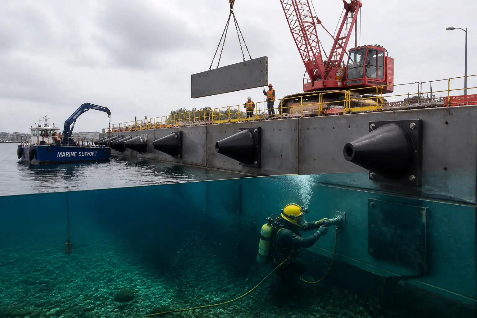
- Underwater bolt tightening and inspection by qualified commercial divers using calibrated subsea torque tools.
- QA/QC inspections, hold/witness points for embedment strength (anchor proof/pull-out tests) and torque verification.
- Final fender contact test using controlled horizontal loading and measurement.
- Documentation, as-built records, and handover.
Exclusions
- Structural design and selection of fender type/capacity (by Designer/Manufacturer).
- Major civil repairs to quay wall beyond local patching and coating touch-up.
- Cathodic protection systems other than isolation kits where specified.
Assumptions
- Work within a controlled berth with port authority permits and vessel movement controls in place.
- Tide and weather windows available to allow safe installation and diving operations.
- Anchor type, grade, and sizes are defined in project drawings/manufacturer data. Where not defined, typical values are indicated and marked [Verify per project specifications].
References
| Document Type | Reference / Number | Revision | Notes |
|---|---|---|---|
| Guideline | PIANC WG33 | ||
| Standard | BS 6349-4 | Design/installation tolerances and performance verification [Verify applicability]. | |
| Standard | BS 8539 | Includes proof testing guidance. | |
| Standard | ASTM E488/E488M | ||
| Code | ACI 318 (Anchoring) | For reference when applicable. | |
| Standard | ISO 1461 | ||
| Standard | ISO 898-1 / ISO 3506 / ASTM A193/A194 | [Verify per project specifications]. | |
| Guideline | IMCA / ADCI | [Verify per project HSE plan and local regulations]. | |
| Standards | ISO 9001 / EN 10204 |
Responsibilities
| Role | Responsibility | Name / Party |
|---|---|---|
| PM | Approve method, ensure permits and insurance in place. | Contractor |
| CM | Daily coordination, lifting plans, interface with diving operations. | Contractor |
| Engineer | Survey checks, set-out tolerances, records. | Contractor |
| Diving Supervisor | Dive plan, toolbox talks, logbooks, video records, emergency preparedness. | Subcontractor |
| QA/QC | ITP compliance, records, calibration control, NCRs. | Contractor |
| HSE | PTW issuance, audits, incident reporting, monitoring. | Contractor |
| Vendor Rep | Confirm torque values, installation details, acceptance of test results. | Supplier |
| Engineer | Witness/approve tests, sign-off IRs. | Client/Engineer |
Resources
| Resource Type | Description | Quantity | Remarks |
|---|---|---|---|
| Manpower | Certified lifting team with banksman. | 1 operator + 3 riggers [Verify] | |
| Manpower | Surface-supplied air team (Supervisor, Diver, Standby Diver, Tender). | 4–5 persons per shift [Verify] | |
| Manpower | Topographic/marine survey support. | 2 | |
| Manpower | Quality and safety site coverage. | 2–3 |
Materials
| Material | Specification / Grade | Quantity | Remarks |
|---|---|---|---|
| Natural rubber compound | PIANC performance verified | As per BOQ | |
| S355/S275 steel, UHMW-PE pads | Coating to ISO 12944 C5M [Verify] | As per BOQ | |
| Grade 40/80 chain [Verify] | ISO 1461 galvanizing | As per BOQ | |
| Carbon steel HDG or stainless | ISO 898-1 / ISO 3506 | As per drawings | |
| Epoxy/vinylester; Class A grout | ASTM C1107 for grout | As required | |
| Marine-grade coatings | ISO 12944 C5M/Im2 [Verify] | As required | |
| Anti-seize compound | [Verify per manufacturer] | As required |
Equipment
| Equipment | Capacity / Type | Quantity | Inspection Required |
|---|---|---|---|
| Crane | 50–100 t [Verify] | 1 | Yes |
| Torque system | Up to 3,000 N·m [Verify] | 1 set | Yes |
| Torque wrench | Up to 1,500–3,000 N·m [Verify] | 2 | Yes |
| Drill | 1 set | Yes | |
| Pull tester | Up to design load [Verify] | 1 | Yes |
| Boat + load cell | Pull ≥ test load [Verify] | 1 | Yes |
| Diving spread | 1 set | Yes | |
| Survey kit | 1 set | Yes |
Prerequisites
- Approved IFC drawings, vendor installation manuals, and this Method Statement with ITP.
- Port Authority permits: Permit to Work, Permit to Dive, lifting permits, berth closure/Notice to Mariners [Verify per Port].
- HSE documentation: task-specific risk assessment, toolbox talks, emergency response plan, dive plan, rescue plan.
- Confirm quay wall capacity and access for crane outriggers; ground bearing pressure check and matting if required.
- Material verification: MTCs for fenders, chains, shackles, bolts; coating DFT reports for panels (pre-delivery) [if available].
- Calibration certificates: torque tools, pull-test rig, load cell, survey equipment (valid within 6 months unless otherwise specified).
- Set-out benchmarks and control points established and verified.
- Tide/current/weather window selected; thresholds defined (e.g., max wind 12 m/s, wave height 0.5 m, current 1 knot) [Verify per project].
- Utilities and obstructions confirmed; underwater pre-dive survey and DP hazard check (intakes/outfalls/eddies) completed.
- Lifting studies and rigging plans approved; lifting points on panels/fenders verified by vendor.
- Manufacturer’s representative availability for key activities (fit-up, torque/sequence, final tests) [if required by spec].
- Isolation kits, anti-seize type, and torque values confirmed with vendor.
Method Sequence
| Step | Activity | Description | Responsibility | Inspection / Hold Point |
|---|---|---|---|---|
| 1 | Receiving, storage, and inspection | Unload fenders, panels, chains, and bolts to laydown area with padding. Inspect for transit damage, coating condition, and completeness. | Storekeeper/QA-QC | Visual inspection, DFT spot check on panels |
| 2 | Survey set-out | Mark centerlines and levels for each fender location on quay face/apron using control points. | Surveyor | Engineer witness |
| 3 | Substrate verification | Confirm concrete grade/strength and thickness at fixings. Take cores or review records as required. | Site Engineer/QA-QC | Hold Point (if unknown strength) |
| 4 | Anchor layout and drilling (if post-installed) | Use vendor template to drill holes. Perform brush–blow–brush cleaning and moisture control per adhesive TDS. | Site Team | QA/QC witness |
| 5 | Anchor installation and curing | Install adhesive/capsule anchors with correct embedment and projection; respect gel/cure times vs temp. | Site Team | Hold Point (pre-load) |
| 6 | Anchor proof/pull-out testing | Select sample anchors and conduct proof/pull-out testing. | QA/QC | Hold Point (Client/Engineer) |
| 7 | Base surface prep and shimming | Clean bearing surfaces; fit shims/packers or grout pads as detailed; check flatness and plumb. | Site Team | QA/QC check |
| 8 | Lift and position fender unit | Lift using designed lifting lugs and spreader; align to marks; fit on studs/anchors; hand-tighten nuts with anti-seize as specified. | Crane crew/Riggers | Engineer witness |
| 9 | Install frontal panel and chains | Attach panel to fender (if separate) and connect tension/shear/weight chains with shackles; mouse pins; fit isolation washers if specified. | Riggers/Divers | QA/QC witness |
| 10 | Underwater bolt tightening | Diver positions sockets and tightens nuts with subsea torque wrench to vendor-specified torque in cross-pattern. Apply anti-seize where required pre-dive. | Diving Team | Hold/Witness Point (torque verification) |
| 11 | Coating touch-up | Repair any coating damage on panels/fixtures using approved system; salt contamination test if in splash zone. | Coating Team | QA/QC check |
| 12 | Final dimensional and torque verification | Topside/underwater verification of alignments, clearances, bolt projections, and torque re-check after settling period. | QA/QC & Divers | Witness Point |
| 13 | Fender contact test | Apply controlled horizontal load to frontal panel using workboat/tug and inline load cell or winch. Measure load and deflection/footprint. | Site Team/Vendor Rep | Hold Point (Client/Engineer) |
| 14 | Handover and demobilization | Clean area, remove temporary works, restore berth, submit dossiers. | Site Team | Final walkdown |
Health, Safety, and Environment – Safety Controls
Key Hazards, Consequences, and Controls
1) Lifting heavy panels/fenders
- Consequence: Crush injuries, dropped objects into water.
- Engineering/Procedural Control: Approved lift plan; certified crane/rigging; use spreader beams and soft slings; secondary retention for small tools; exclusion zones and tag lines; weather limits [Verify].
- PPE: Helmet with chin strap, cut-resistant gloves, safety boots, lifejacket with fall-arrest capability where near edge.
- Collective Measures: Edge barriers, spotters, radio comms, banksman control.
- Inspection/Permit: Daily crane/rigging inspection, lifting permit, pre-lift meeting.
2) Working at quay edge and drowning risk
- Consequence: Fall into water, hypothermia, drowning.
- Control: Edge protection where practicable, fall arrest anchored to certified points, man-safe ladders within 25 m, rescue boat on standby.
- PPE: 150 N auto-inflating lifejacket, fall-arrest harness and double lanyard.
- Collective: Lifebuoys with throw lines, lighting for night work.
- Inspection/Permit: PTW, rescue drill records, supervisor sign-off.
3) Diving operations (entanglement, differential pressure, poor visibility)
- Consequence: Serious injury/fatality.
- Control: IMCA/ADCI-compliant dive plan; surface-supplied air; minimum team (Supervisor, Diver, Standby, Tender); umbilical management; pre-dive hazard survey for intakes/outfalls; lock-out of thrusters/nearby vessel movements; red flags/Alpha flag and Notice to Mariners.
- PPE: Diving helmet, dry/wet suit, gloves, comms, cutting-resistant umbilical.
- Collective: Rescue equipment ready, first aid oxygen, emergency recovery plan.
- Inspection/Permit: Permit to Dive, pre-dive checklist, equipment certifications, medical fitness certificates [Verify per local regulations].
4) High torque hydraulic tools
- Consequence: Pinch/strain injuries, hose burst injection injury.
- Control: Pressure-rated hoses with whip checks; tool guards; two-hand operation; training; pressure relief set per OEM; keep hands clear of pinch points.
- PPE: Impact gloves, eye/face protection, hearing protection.
- Collective: Barriers around tool area, spill kits.
- Inspection/Permit: Tool inspection logs, calibration certs, hydraulic hose inspection tags.
5) Drilling and anchor installation (if applicable)
- Consequence: Silica dust inhalation, hand-arm vibration, flying debris.
- Control: Wet drilling or on-tool extraction; HAVS monitoring; use of depth stops; brush–blow–brush with compressed air fitted with guard and regulator.
- PPE: Eye protection, FFP3 respirator, gloves, hearing protection.
- Collective: Local extraction, area barricading.
- Inspection/Permit: PTW, equipment inspection, HAVS records.
6) Marine traffic and berthing forces during test
- Consequence: Collision, uncontrolled loads.
- Control: Marine coordinator; tug/workboat brief; test plan with max load; fender test at slack tide; establish exclusion zone.
- PPE: Lifejackets, radios, helmets.
- Collective: Patrol boat, signage.
- Inspection/Permit: Marine permit, VTS coordination records.
7) Manual handling of chains/hardware
- Consequence: Strains, crush injuries.
- Control: Use chain hoists; break down lifts; team lifts; proper pinch-point awareness.
- PPE: Gloves, steel-toe boots.
- Collective: Mechanical aids, clear walkways.
- Inspection/Permit: Toolbox talk, supervision.
8) Corrosion protection and coating touch-up (solvents)
- Consequence: Dermal/respiratory exposure, fire risk.
- Control: Use low-VOC marine coatings where possible; follow TDS; ventilate; no ignition sources; waste control.
- PPE: Chemical-resistant gloves, respirator per SDS, goggles.
- Collective: Fire extinguisher nearby, spill kits.
- Inspection/Permit: Hot work permit if applicable; SDS review; VOC approvals [Verify per HSE plan].
Note: All controls to be verified per project HSE plan and local regulations.
Environmental Controls
- Water quality protection: Use drip trays and absorbent booms around workboat and quay; biodegradable hydraulic fluids preferred for subsea tools [Verify].
- Debris and dropped object prevention: Tool lanyards; mesh nets under work area where practicable; immediate retrieval plan for dropped items.
- Noise and working hours: Comply with port restrictions; use low-noise equipment and maintain mufflers.
- Waste management: Collect drilling dust/slurry; dispose of spent adhesive cartridges, solvent rags, and coating tins as hazardous waste per regulations.
- Coating/paint control: Prevent overspray; use containment and tidal windows; capture paint flakes from touch-up scraping.
- Silt/turbidity: Avoid seabed disturbance; if underwater drilling is required, install silt curtain subject to current conditions [Verify].
- Spill response: Spill kits staged; crew trained; reportable spill thresholds understood; immediate containment and notification chain defined.
- Wildlife and habitat: Observe marine fauna exclusion guidance if applicable; lighting minimized to reduce spill into water at night [Verify per EMP].
Quality Assurance and Quality Control
Controls and Records
- Submittals: Vendor datasheets, installation manuals, MTCs (EN 10204 3.1), coating systems, torque values, adhesive TDS.
- Calibrations: Torque tools, pull tester, load cell, survey equipment within 6 months or per project requirement.
- Traceability: Record serial/heat numbers of chains, shackles, anchors to installed location.
- Inspection/Test Frequencies:
- Material receiving: 100% visual; DFT spot check ≥10% of panels.
- Anchor installation: 100% embedment/projection check; proof/pull testing: ≥2% anchors or min 3 per fender location [Verify].
- Torque: 100% first-pass; 100% final pass; breakaway spot checks ≥10% of bolts after 24–48 h [Verify].
- Dimensional/level: 100% of fender units.
- Tolerances and Acceptance (typical unless specified otherwise):
- Set-out: ±10 mm horizontal; ±5 mm vertical.
- Anchor embedment depth: ±5 mm; projection: ±3 mm.
- Panel flatness: L/1000; contact at test load: ≥90% panel width.
- Galvanizing: ISO 1461 min local thickness 70–100 µm [Verify per spec].
- Hold/Witness Points:
- HP1: Concrete strength confirmation (if uncertain).
- HP2: Anchor proof/pull-out testing.
- HP3: Underwater torque verification of first fender.
- HP4: Fender contact test.
- Documentation: IRs, checklists, dive videos, torque logs, pull test reports, calibration certs, coating DFT logs, as-builts.
- Nonconformities: Record NCRs; corrective actions may include re-drilling/replacing anchors, re-torque, re-coating, or panel re-alignment.
- Training/Competence: Divers commercially certified; riggers/lifting team certified; torque tool operators trained and authorized.
Attachments
- Approved IFC drawings and fender layout.
- Vendor installation manuals and datasheets (fenders, panels, chains, anchors).
- Lift plans and rigging drawings with crane load charts.
- Dive plan, risk assessment, PTW templates, emergency response plan.
- Torque schedule by bolt size and location [Per vendor, attach table].
- Anchor testing plan and locations.
- Coating repair system data sheets and method.
- Contact test procedure and sketch.
- Calibration certificates (torque tools, pull tester, load cell, survey kit).
- As-built drawing template and inspection checklists.
This content is a read-only public reference. Download or customize to get an editable version.
ITP preview
The first inspection activities from the linked ITP for Method Statement: Installation of Rubber Fender System on Quay Wall (with Underwater Bolt Tightening, QA/QC, and Final Contact Test):
| Activity | Inspection / Test | Acceptance Criteria | Responsibility | Record |
|---|---|---|---|---|
| Material receiving inspection | Visual, DFT spot checks, certificate verification (EN 10204 3.1) | No damage/corrosion; coating within TDS; documentation complete. | Contractor QA/QC, Engineer (surveillance) | Material IR, photos, DFT log |
| Survey set-out verification | Dimensional survey | Within ±10 mm (H), ±5 mm (V) [Verify]. | Surveyor/QA-QC, Engineer (witness) | Survey report, redlines |
| Concrete strength confirmation | Review test reports/cores/Schmidt [Verify] | f'c ≥ 30 MPa [Verify]. | Contractor QA/QC, Engineer (hold if required) | Test report, IR |
Showing 3 of 12 inspection activities. View full ITP →
Related Inspection and Test Plan
An Inspection and Test Plan (ITP) is available for Method Statement: Installation of Rubber Fender System on Quay Wall (with Underwater Bolt Tightening, QA/QC, and Final Contact Test). The ITP defines the inspection activities, acceptance criteria, hold and witness points, responsible parties, and records required to verify the work described in this method statement.
View the Method Statement: Installation of Rubber Fender System on Quay Wall (with Underwater Bolt Tightening, QA/QC, and Final Contact Test) ITP →Frequently asked questions
Continue with related Quollnet resources connected to this method statement.