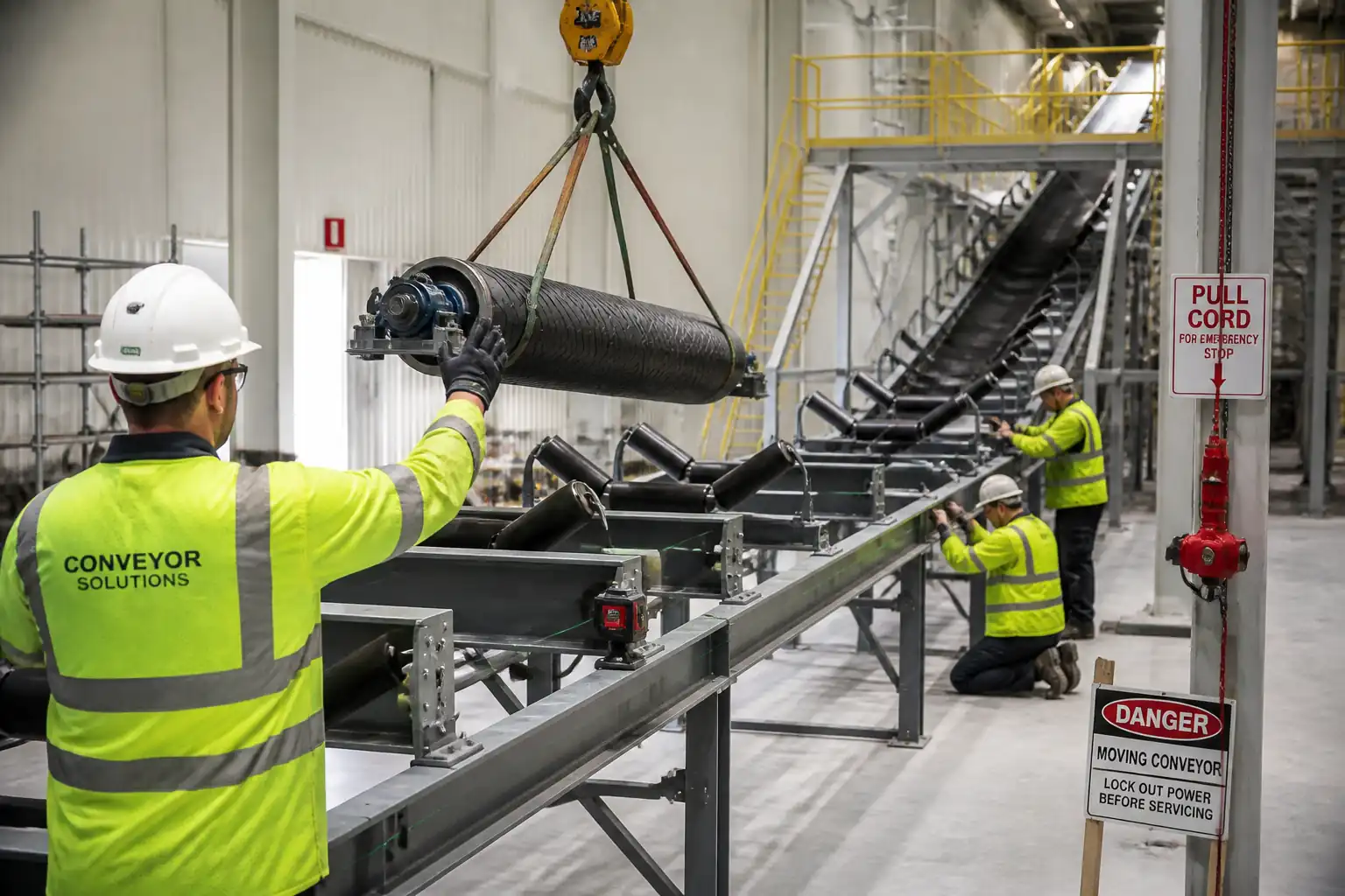

Method Statement – Installation of Industrial Conveyor System (Mechanical, Electrical & Functional Testing) – Method Statement
AI-assisted method statement with matching ITP, PDF download, and Excel export.
More than a static template
Unlike a downloadable Word or PDF template, this method statement is an AI-assisted editable starting point connected directly to a matching Inspection and Test Plan. Every section is structured, project-adaptable, and ready to export.
- AI-assisted drafting — Customize every section with AI for your specific project scope.
- Linked ITP — A matching inspection and test plan is generated alongside the method statement.
- Multiple export formats — Download as a formatted PDF or editable Excel spreadsheet.
- Editable starting point, not a final document — Review, verify, and adjust all content against your project requirements before use.
Static template vs. Quollnet workflow
| Feature | Static template | Quollnet |
|---|---|---|
| Project-specific content | Manual fill-in required | AI-assisted customization |
| Linked ITP | Separate document, no link | Matching ITP included |
| Export formats | Usually PDF only | PDF and Excel |
| Structured sections | Free-form layout | 13 standardized sections |
| Saved to your account | Local file only | Cloud-saved, reusable |
| Content accuracy | You verify everything | AI-assisted, you still verify |
| Cost | Often free but time-intensive | Free to customize and download |
What you can customize
When you save this method statement to your account, every section becomes editable. The following 13 sections are included:
- Scope — Defines the activity and its boundaries.
- References — Standards, specifications, and drawings.
- Responsibilities — Roles and accountabilities.
- Resources — Labour, plant, and equipment summary.
- Materials — Materials and compliance requirements.
- Equipment — Tools and equipment details.
- Prerequisites — Hold points and pre-conditions.
- Method sequence — Step-by-step construction sequence.
- Safety controls — HSE risk controls and PPE.
- Environmental controls — Environmental mitigation measures.
- QA/QC — Quality inspection and test requirements.
- ITP — Inspection and Test Plan table (has its own page).
- Attachments — Referenced drawings and documentation.
Why this method statement is used
This method statement is used to define and communicate the approved procedure for carrying out method statement – installation of industrial conveyor system (mechanical, electrical & functional testing) on site. It ensures the work is planned in advance, the correct resources and controls are in place, and all personnel understand responsibilities, sequence, quality requirements, and safety controls before work begins. It aligns site execution with the documented scope and acceptance expectations.
Who uses this method statement
This method statement is used by contractors, site supervisors, project engineers, QA/QC engineers, HSE officers, consultants, and client representatives. It serves as a shared reference for planning, execution, supervision, inspection, and approval of the activity on site.
When it is prepared and submitted
The method statement is prepared before the work activity starts and submitted as part of the pre-construction documentation package for review and approval.
Who reviews or approves it
The method statement is usually submitted to the client representative, consultant, resident engineer, or project management consultant for review and approval before the work commences.
Important approval note
This method statement is an AI-assisted editable starting point, not a pre-approved document. Before use on any project, all content must be reviewed and approved by the relevant parties (superintendent, principal contractor, or client representative) in accordance with your contract and project quality plan.
For example: if your specification requires a departure from a referenced standard, that departure must be documented and approved separately — this method statement will not capture that automatically. Always verify against your applicable drawings, specifications, and regulatory requirements.
Method statement content
Scope
Overview
This method statement covers the complete installation and pre-commissioning of an industrial belt conveyor system, including:
- Structural supports and stringers
- Head/tail pulleys, snub and take-up assemblies, idlers/rollers
- Drive units (motor, gearbox, coupling, brakes), VFD and controls coordination
- Belt installation, splicing (hot vulcanized or mechanical), tensioning, and tracking
- Guards, emergency devices (pull cords, E-stops), signage, and safety interlocks
- Electrical terminations, earthing/bonding, instrumentation and functional logic checks
- Trial running (no-load and loaded), QA/QC verifications, ITP hold/witness points, and records
Locations
- Conveyor line(s) as per IFC drawings and layout plans [Verify per project specifications].
Exclusions
- Upstream/downstream process equipment commissioning beyond conveyor functional testing
- Permanent power supply beyond MCC/VFD termination point
- Civil foundation construction (assumed complete and accepted)
Interfaces
- Civil/structural works (foundations, embedded items)
- Electrical power distribution, MCC/VFD, instrumentation and control system
- Adjacent conveyors/chutes/transfer points
- HSE and Permit-to-Work systems
Objectives
- Deliver a fully installed, aligned, tensioned, guarded, and functionally tested conveyor system ready for client commissioning handover.
References
| Document Type | Reference / Number | Revision | Notes |
|---|---|---|---|
| CEMA – Belt Conveyors for Bulk Materials (7th Ed.) | Design/installation good practice for belt conveyors. | ||
| ISO 14890 – Conveyor belts — Specification for rubber- or plastics-covered conveyor belts | Belt type, grade, and testing [Verify per project specifications]. | ||
| ISO 14120 – Safety of machinery — Guards — General requirements | Guard design and construction. | ||
| ISO 13857 – Safety of machinery — Safety distances to prevent hazard zones being reached by upper and lower limbs | Guarding distances and openings [Verify per project HSE plan and local regulations]. | ||
| ISO 13849-1 – Safety-related parts of control systems | Safety PLC/interlock performance levels when applicable. | ||
| IEC 60204-1 – Safety of machinery — Electrical equipment of machines | Electrical integration and protection. | ||
| IEC 60364-6 – Low-voltage electrical installations — Verification | Insulation resistance, polarity, continuity tests. | ||
| IEC 61800 series – Adjustable speed electrical power drive systems | VFD installation and testing guidance. | ||
| DIN/EN 618 & EN 620 – Continuous handling equipment and systems (Belt conveyors) | Safety and calculation guidance [Verify per project specifications]. | ||
| ASTM C1107 – Non-shrink grout | Baseplate grout for supports and machinery seating. | ||
| ISO 898 (bolts) / ISO 3506 (stainless fasteners) | Fastener grades and properties; torque per manufacturer. |
Responsibilities
| Role | Responsibility | Name / Party |
|---|---|---|
| Contractor Project Manager | Overall delivery, resources, compliance with specifications and HSE. | Contractor |
| Construction/Site Manager | Day-to-day supervision, sequence control, coordination with trades. | Contractor |
| QA/QC Engineer | Inspection and test implementation, ITP compliance, records, NCR control. | Contractor |
| HSE Manager/Officer | Risk assessments, permits, toolbox talks, monitoring and incident management. | Contractor |
| Surveyor | Layout verification, centerline/EL control, as-built survey. | Contractor |
| Mechanical Supervisor & Fitters | Mechanical installation, alignment, belt splicing and tensioning. | Contractor |
| Electrical/Instrumentation Supervisor & Technicians | Terminations, earthing, VFD commissioning support, interlocks, loop checks. | Contractor |
| Rigging Supervisor & Riggers | Lifting plans, rigging operations, crane/hoist inspection. | Contractor |
| Engineer/Consultant Representative | Design conformity, method approval, witnessing at hold/witness points. | Engineer |
| Client/Owner Representative | Compliance with site rules; acceptance of works; interface coordination. | Client |
Resources
| Resource Type | Description | Quantity | Remarks |
|---|---|---|---|
| Personnel | 1 | ||
| Personnel | 1 | ||
| Personnel | 4–10 [Verify per project] | ||
| Personnel | 3–6 [Verify per project] | ||
| Personnel | 2–4 [Verify per project] | ||
| Personnel | 2–4 [Verify per project] | ||
| Personnel | 1–2 |
Materials
| Material | Specification / Grade | Quantity | Remarks |
|---|---|---|---|
| Structural steel supports | Coating per project; galvanizing per ISO 1461 if specified | As per BOQ | |
| Pulleys | Concentricity and balance per manufacturer; lagging hardness [Verify] | As per drawings | |
| Idlers/Rollers | CEMA/ISO compliant; run-out ≤0.5 mm [Verify] | As per drawings | |
| Conveyor belt | ISO 14890 grade, tensile rating, cover thickness [Verify] | As per belt list | |
| Drive assembly | IEC 60034 motor; gearbox ratio & service factor per design | 1 set/drive | |
| Safety devices and sensors | ISO 13849-1 PL rating [Verify]; IP rating ≥ IP65 typical [Verify] | As per I/O list | |
| Guarding | ISO 14120, openings per ISO 13857 [Verify] | As required | |
| Non-shrink grout | ASTM C1107, fluid/flowable grade; 28-day strength per design [Verify] | As required | |
| Bolts, nuts, washers | ISO 898 Class 8.8/10.9 or per spec; torque per MFR | As required |
Equipment
| Equipment | Capacity / Type | Quantity | Inspection Required |
|---|---|---|---|
| Lifting equipment | As per lift plan [Verify] | 1 | Daily pre-use + periodic certificate |
| Chain blocks / hoists | 1–3 t [Verify] | 2–4 | LOLER/ASME certificate [Verify] |
| Total station / theodolite / laser level | 1 | Calibration in date | |
| Laser alignment tool and feeler gauges | 1 | Calibration in date | |
| Torque wrench | 10–500 N·m range [Verify] | 2 | Calibration in date |
| Belt winder / winch and snatch blocks | As per belt mass [Verify] | 1 | LOLER/ASME certificate [Verify] |
| Vulcanizing press, skivers, presses, thermometers | 1 set | Calibration and MFR procedure | |
| Belt tension meter / load cell (if provided) | 1 | Calibration in date | |
| Tachometer, vibration meter, IR thermometer/thermal camera | 1 each | Calibration in date |
Prerequisites
- Approved IFC drawings, vendor manuals, and this Method Statement & ITP.
- Foundations cast, cured, surveyed, and accepted. Anchor bolt locations and elevation verified; grout surfaces clean and roughened per MFR.
- Utility scan and service isolation confirmed; work area barricaded and access arranged.
- Lifting plan and rigging studies approved; cranes/hoists certified; rigging gear inspected.
- Electrical PTW and LOTO procedures prepared; temporary power available for tools.
- All measuring and test equipment calibrated; certificates available.
- Materials inspected on receipt; belts stored flat, dry, at 10–30°C; pulleys/idlers protected from damage and contamination.
- HSE documents: task-specific risk assessments, toolbox talks, hot work permits for vulcanizing as needed [Verify per project HSE plan and local regulations].
- Manufacturer representatives notified for critical stages (drive alignment, splicing, commissioning) if required by contract.
- Hold/Witness points agreed with Engineer for: baseplate leveling before grouting, drive alignment, belt splicing, pre-energization, trial runs.
Method Sequence
| Step | Activity | Description | Responsibility | Inspection / Hold Point |
|---|---|---|---|---|
| 1 | Survey and setting out | Establish conveyor centerline and elevations using total station. Mark support positions, transfer levels to baseplates. | Surveyor / Site Engineer | Checkpoints vs IFC within tolerances |
| 2 | Install supports & stringers | Position frames/stringers, shim to level, temporarily bolt. Confirm plumb/level before grouting. | Mechanical Supervisor | Visual and level checks |
| 3 | Grouting of baseplates | Clean surfaces, pre-wet if required, mix non-shrink grout per MFR, place and cure. Protect from vibration until initial set. | Mechanical Supervisor | Material batch and placement |
| 4 | Install pulleys (head/tail/snub/take-up) | Lift and place pulleys with bearings, ensure correct lagging orientation, set axial positions, pre-align to centerline. | Mechanical Supervisor / Riggers | Dimensional & position check |
| 5 | Install idlers/rollers | Fit carrying and return idlers per spacing; ensure equal troughing angles and heights; install training idlers at specified locations. | Mechanical Supervisor | Random sampling and visual |
| 6 | Install drive unit (motor/gearbox/coupling/brake) | Place and align gearbox to pulley shaft; install motor and coupling. Torque bolts per MFR; install guards temporarily removed later for checks. | Mechanical & Electrical Supervisors | Dimensional & torque check |
| 7 | Electrical installation & earthing | Route and terminate power/control cables to motor, sensors, pull-cords, E-stops. Install earthing/bonding jumpers to all metallic parts. | Electrical Supervisor | Visual & continuity |
| 8 | Install belt | Position belt roll on winder, thread belt through path over idlers/pulleys using winch and draw rope. Protect edges; avoid twisting. | Mechanical Supervisor / Splicing Team | Handling and threading checks |
| 9 | Belt splicing (hot vulcanized or mechanical) | Prepare splice per MFR: cut, step/biased scarf, clean, apply adhesives/compounds, cure with press per temperature/pressure/time. Cool and trim. | Certified Splicing Technicians | MFR representative witness if required |
| 10 | Tensioning & take-up setup | Set gravity or screw take-up to initial tension. Adjust per MFR to achieve required sag and start-up traction. | Mechanical Supervisor | Gauge/scale readings |
| 11 | Belt tracking & alignment verification | Jog conveyor, correct tracking by adjusting idlers/training idlers and pulleys. Verify final alignment of all components. | Mechanical Supervisor | Operational observation |
| 12 | Install/verify guards & safety devices | Fit fixed/hinged guards; install pull-cords, E-stops, drift/rip switches. Verify labeling and access clearances. | Mechanical & Electrical Supervisors | Physical and functional checks |
| 13 | Pre-energization checks (MEI) | Complete checklists: torque mark, lubrication, oil levels, rotation by hand, phase sequence, insulation, earthing continuity, signage, housekeeping. | QA/QC + Electrical Lead | ITP Hold Point |
| 14 | No-load trial run | Energize and run for 2–4 hours [Verify]. Monitor current, vibration, temperature, tracking, noise. Test E-stops and pull-cords. | Commissioning Team | Witness by Engineer |
| 15 | Loaded trial run | Introduce material gradually to design rate. Observe loading, transfer points, tracking, dust/ spillage, and power draw. | Commissioning Team / Operations | Witness by Engineer |
| 16 | Punch list close-out & documentation | Rectify any deficiencies; submit as-builts, calibration, test records, O&M manuals, and training records. | Contractor PM / QA/QC | Final inspection |
Safety Controls
Principal Task-Specific Hazards and Controls
- Hazard: Lifting and rigging of pulleys, drives, and frames
- Likely consequence: Crush injury, dropped load, fatality
- Engineering/procedural control: Engineered lift plan; certified crane/hoists and rigging; exclusion zones; taglines; competent rigger in charge
- Required PPE: Hard hat, safety boots, cut-resistant gloves, eye protection, high-vis
- Collective preventive measure: Physical barriers and banksman control; load path kept clear
-
Inspection/permit/supervision: Pre-use rigging inspection; current certificates; Lift Permit; Supervisor and Rigger-in-Charge present [Verify per project HSE plan and local regulations]
-
Hazard: Work at height on galleries and head/tail platforms
- Likely consequence: Fall from height, serious injury
- Engineering/procedural control: Complete guardrails; use certified scaffolds or MEWP; 100% fall arrest where rails incomplete; anchor points certified
- PPE: Full-body harness with double lanyard where required
- Collective measure: Temporary barriers and toe boards; debris nets where applicable
-
Inspection/permit/supervision: Working at Height Permit; scaffold/MEWP inspection tag; competent person inspection
-
Hazard: Pinch/nip points at pulleys and rollers during installation and testing
- Likely consequence: Amputation/crush injuries
- Engineering/procedural control: Lock-out mechanical isolations; fit guards before energization; use jog mode at low speed; safe approach distances per ISO 13857
- PPE: Close-fitting clothing, gloves suited to task, eye protection
- Collective measure: Interlocked guards; pull-cords along full length; signage
-
Inspection/permit/supervision: Pre-energization inspection checklist; HSE supervision during trials
-
Hazard: Stored energy from gravity take-up, springs, or belt tension
- Likely consequence: Sudden movement causing impact injuries
- Engineering/procedural control: Restrain take-up with pins/blocks during maintenance; controlled tensioning procedure; barricade take-up zone
- PPE: Helmet, gloves, eye protection
- Collective measure: Mechanical chocks/energy isolation
-
Inspection/permit/supervision: Isolation permit; supervisor authorization
-
Hazard: Electrical shock/arc flash during terminations and tests
- Likely consequence: Severe burns, fatality
- Engineering/procedural control: LOTO; verify absence of voltage; insulated tools; arc-flash study settings; correct PPE category; only authorized electricians
- PPE: Arc-rated clothing, face shield, insulated gloves, dielectric footwear
- Collective measure: Barriers and warning signs; test-before-touch
-
Inspection/permit/supervision: Electrical PTW; LOTO log; competent supervisor; testing per IEC 60364-6
-
Hazard: Hot work for belt vulcanizing and use of solvents/adhesives
- Likely consequence: Burns, fire, toxic exposure
- Engineering/procedural control: Hot Work Permit; fire watch; extinguishers; ventilation; follow MFR SDS for adhesives and ensure LEV
- PPE: Heat-resistant gloves, eye/face protection, respirator if required
- Collective measure: Fire blankets/screens; flammable storage cabinets
-
Inspection/permit/supervision: Gas testing where applicable; permit sign-off; SDS on site
-
Hazard: Noise and vibration during trial runs
- Likely consequence: Hearing damage; ergonomic strain
- Engineering/procedural control: Limit exposure duration; maintain equipment to reduce noise; use remote monitoring where possible
- PPE: Hearing protection (SNR per site rules)
- Collective measure: Acoustic barriers if needed
-
Inspection/permit/supervision: Noise survey if required; HSE oversight
-
Hazard: Manual handling of idlers/belts
- Likely consequence: Strains and sprains
- Engineering/procedural control: Use mechanical aids, team lifting, proper technique training
- PPE: Gloves, safety footwear
- Collective measure: Trolleys and lifting frames
-
Inspection/permit/supervision: Manual handling assessment and supervision
-
Hazard: Slips, trips, and housekeeping deficits
- Likely consequence: Minor to serious injuries
- Engineering/procedural control: Keep walkways clear; immediate cleanup of grease/grout; route cables safely
- PPE: Slip-resistant footwear
- Collective measure: Good lighting; cable ramps
-
Inspection/permit/supervision: Daily housekeeping inspections
-
Hazard: Energized testing with rotating parts
- Likely consequence: Entanglement, impact injuries
- Engineering/procedural control: Only essential personnel in area; use fixed speed limits for jog; confirm guards in place
- PPE: Close-fitting clothing, eye protection, hearing protection
- Collective measure: Barricades and lockable control stations
- Inspection/permit/supervision: Commissioning permit; supervisor present throughout testing.
Environmental Controls
- Spill prevention: Store oils/greases with secondary containment; spill kits at workfront; immediate cleanup with absorbents. Waste oils to licensed recycler.
- Grout and wash water: Prevent discharge to drains; collect and dispose per local regulations; use wet vac/recovery containers.
- Adhesives/solvents (vulcanizing): Use in ventilated areas; keep lids closed; low-VOC products where available; dispose of wipes/containers as hazardous waste.
- Noise: Schedule high-noise activities daytime; monitor if near receptors; maintain equipment to minimize noise levels [Verify per project EMP].
- Dust and debris: Keep belt path clean; use covers at transfer points if required; avoid sweeping into drains.
- Waste segregation: Separate scrap steel, belt trimmings, packaging, and e-waste. Use labeled bins; maintain waste transfer notes.
- Energy efficiency: Verify idler alignment and lubrication to reduce frictional losses; VFD parameters optimized for soft start/stop.
- Wildlife and stormwater: Protect drainage; no materials stored within buffer zones; install silt socks if outdoors.
- Compliance: Follow project Environmental Management Plan, permits, and local regulations [Verify per project HSE plan and local regulations].
QA/QC
General
- Implement ITP with defined Hold (H), Witness (W), and Review (R) points.
- Use calibrated instruments; record serial numbers and calibration due dates on test sheets.
Dimensional and Alignment Criteria [Verify per project specifications]
- Centerline deviation: ≤ ±5 mm over 10 m; cumulative ≤ ±15 mm over full length.
- Stringer levelness: ≤ ±3 mm over 10 m.
- Support plumb: ≤ 2 mm/m.
- Pulley alignment: face squareness ≤ 0.5 mm/m; level across face ≤ 1 mm; axial position ±3 mm.
- Shaft/coupling alignment: parallel offset ≤ 0.2 mm; angular ≤ 0.2 mm/100 mm.
- Idler run-out: ≤ 0.5 mm; height uniformity ±2 mm; lateral offset ≤ 1 mm.
Fastening and Grouting
- Bolt grade and length verified; torque within ±10% of specified; torque-marked and rechecked after 24 h if required.
- Grout: ASTM C1107 compliant; placement temperature 10–32°C; cube/cylinder strength per spec; no voids; full bearing.
Belt and Splice Quality
- Belt type and rating per ISO 14890 and data sheet.
- Splice alignment offset ≤ 2 mm; thickness variation ≤ ±1 mm; cure parameters within MFR ranges; visuals free of blisters/voids; adhesion test if specified.
- Initial tension set to achieve sag 1–2% of idler spacing (typical) and traction margin as per MFR.
Electrical/Controls
- Insulation resistance ≥ 1 MΩ @ 500 VDC (cables and motor, cold) unless MFR states otherwise.
- Earth continuity < 1 Ω typical between bonded components (or per project spec).
- Correct phase rotation; control I/O loop checks 100%.
- Safety devices: E-stops and pull-cords to trip within ≤ 1 s; actuation force 50–150 N [Verify]; interlocks SIL/PL level per design.
Functional Tests
- No-load run 2–4 h: current within nameplate ±10% at rated speed; temperature rise of bearings ≤ 40°C above ambient; vibration within ISO 10816/20816 Zone A/B; stable tracking.
- Loaded run to design rate: throughput ≥ 95–100% of design; no abnormal spillage; power draw within design; start/stop sequences and interlocks proven.
Hold/Witness Points (minimum)
- H: Support/stringer level verified before grouting.
- H: Drive installation and shaft alignment.
- H: Belt splice setup and completion.
- H: Pre-energization checks.
- W: No-load and loaded trial runs.
Records
- Survey/as-built reports, alignment reports, torque logs, grout batch sheets and test results, belt splice logs with cure charts, electrical test sheets, loop check sheets, functional test reports, punch list and close-out, O&M manuals, training records, spare parts list.
Attachments
- Checklists: Pre-grout, alignment, torque, pre-energization, safety devices
- Test sheets: Insulation resistance, earth continuity, vibration/temperature logs
- Grout records: Batch sheets, cube/cylinder results
- Belt splice dossier: Procedure, qualifications, cure charts, photos
- Manufacturer manuals: Motor, gearbox, coupling, VFD, sensors
- Certificates: Calibration, lifting gear, personnel qualifications
- Drawings: IFC general arrangement, sections, belt routing, schematics
- Training and O&M: Attendance records, O&M manuals, spare parts lists
This content is a read-only public reference. Download or customize to get an editable version.
ITP preview
The first inspection activities from the linked ITP for Method Statement – Installation of Industrial Conveyor System (Mechanical, Electrical & Functional Testing):
| Activity | Inspection / Test | Acceptance Criteria | Responsibility | Record |
|---|---|---|---|---|
| Incoming materials inspection (supports, pulleys, idlers, belt) | Check certificates, dimensions, damage; storage conditions | Conformity to PO/datasheets; no damage; certificates present | Contractor: Inspect; QA/QC: Verify; Engineer: Witness (W) | Material inspection report & MIR/MTCs |
| Foundation and baseplate preparation | Surface condition, anchor locations/levels | Clean, level within tolerance; anchors within ±3 mm location, ±3 mm level | Contractor: Perform; QA/QC: Verify; Engineer: Witness (W) | Pre-installation checklist & survey |
| Support and stringer installation | Plumb/level measurements | Plumb ≤ 2 mm/m; levelness ≤ ±3 mm over 10 m | Contractor: Install; QA/QC: Verify; Engineer: Hold (H) before grouting | Installation checklist |
Showing 3 of 16 inspection activities. View full ITP →
Related Inspection and Test Plan
An Inspection and Test Plan (ITP) is available for Method Statement – Installation of Industrial Conveyor System (Mechanical, Electrical & Functional Testing). The ITP defines the inspection activities, acceptance criteria, hold and witness points, responsible parties, and records required to verify the work described in this method statement.
View the Method Statement – Installation of Industrial Conveyor System (Mechanical, Electrical & Functional Testing) ITP →