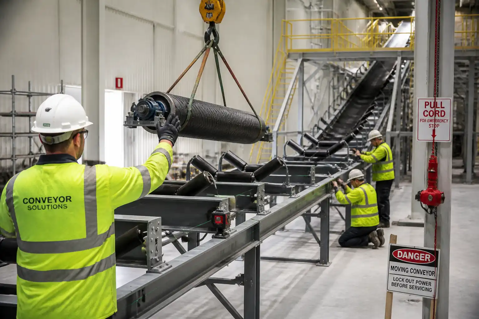

Inspection and Test Plan for Method Statement – Installation of Industrial Conveyor System (Mechanical, Electrical & Functional Testing)
AI-assisted inspection and test plan connected to a method statement, with PDF and Excel export.
More than a static template
Unlike a downloadable Word or PDF template, this ITP is an AI-assisted editable starting point directly connected to its method statement. Every inspection activity, hold point, and acceptance criterion is structured and ready to adapt to your project.
- AI-assisted customization — Tailor inspection activities and acceptance criteria to your specific project scope.
- Linked method statement — This ITP is connected to the corresponding method statement describing the work sequence.
- Multiple export formats — Download as a formatted PDF or editable Excel spreadsheet.
- Editable starting point, not a final document — Review and verify all content against your project specifications and standards before use.
What you can customize
When you save this ITP to your account, every inspection row becomes editable. You can add, remove, or modify:
- Inspection activity — Description of what is being inspected.
- Inspection type — Hold point (H), Witness point (W), Review (R), or Monitor (M).
- Responsibility — Contractor, subcontractor, engineer, or client.
- Frequency — How often the inspection occurs.
- Acceptance criteria — Referenced standard or specification requirement.
- Records — Forms, test reports, or checklists required as evidence.
Why this ITP is used
To ensure each installation stage is verified against standards and project specifications, reducing risk and assuring quality.
Who uses this inspection and test plan
Contractor supervisors, QA/QC inspectors, and Engineer/Client representatives use it to plan and witness inspections.
When this ITP is prepared and submitted
Applied from materials receipt through mechanical completion to trial runs prior to commissioning.
Who receives or approves this ITP
Engineer/Client representative for review and approval.
Inspection scope
Covers materials receipt, structural installation, alignment, grouting, belt splicing, electrical verifications, safety devices, and functional trials.
Typical hold, witness, and review points
H: Support leveling, drive alignment, belt splicing, pre-energization. W: No-load and loaded trials. R: Handover dossier.
Typical inspection records
Checklists, alignment reports, torque logs, grout tests, splice cure charts, electrical test sheets, loop checks, trial run reports, as-builts.
Important approval note
This ITP is an AI-assisted editable starting point, not a pre-approved document. Before use on any project, all inspection activities, hold points, and acceptance criteria must be reviewed and approved by the relevant parties (superintendent, principal contractor, or client representative) in accordance with your contract and project quality plan.
Always verify acceptance criteria against your applicable drawings, specifications, and regulatory requirements. Hold points must be confirmed with the relevant authority before work proceeds past that point.
Inspection and test plan
| Activity | Inspection / Test | Acceptance Criteria | Responsibility | Record |
|---|---|---|---|---|
| Incoming materials inspection (supports, pulleys, idlers, belt) | Check certificates, dimensions, damage; storage conditions | Conformity to PO/datasheets; no damage; certificates present | Contractor: Inspect; QA/QC: Verify; Engineer: Witness (W) | Material inspection report & MIR/MTCs |
| Foundation and baseplate preparation | Surface condition, anchor locations/levels | Clean, level within tolerance; anchors within ±3 mm location, ±3 mm level | Contractor: Perform; QA/QC: Verify; Engineer: Witness (W) | Pre-installation checklist & survey |
| Support and stringer installation | Plumb/level measurements | Plumb ≤ 2 mm/m; levelness ≤ ±3 mm over 10 m | Contractor: Install; QA/QC: Verify; Engineer: Hold (H) before grouting | Installation checklist |
| Grouting of baseplates | Grout batch review; flow; temperature; cubes/cylinders | ASTM C1107 compliant; strength per spec; void-free bearing | Contractor: Place; QA/QC: Verify; Engineer: Witness (W) | Grout logs & test results |
| Pulley installation and alignment | Laser/string line; level check | Face squareness ≤ 0.5 mm/m; level across face ≤ 1 mm; axial ±3 mm | Contractor: Install; QA/QC: Verify; Engineer: Witness (W) | Alignment report |
| Drive unit installation & coupling alignment | Laser alignment; torque check | Offset ≤ 0.2 mm; angular ≤ 0.2 mm/100 mm; torque within ±10% | Contractor: Install; QA/QC: Verify; Engineer: Hold (H) | Alignment & torque sheets |
| Idler/roller installation | Run-out, height and spacing checks | Run-out ≤ 0.5 mm; height ±2 mm; spacing ±10 mm | Contractor: Install; QA/QC: Verify; Engineer: Witness (W) | Idler installation log |
| Electrical terminations & earthing/bonding | Continuity/earth resistance; insulation resistance; phase rotation | IR ≥ 1 MΩ @ 500 VDC; earth continuity < 1 Ω; correct rotation | Contractor: Perform; QA/QC: Verify; Engineer: Hold (H) | Electrical test sheets |
| Belt installation and threading | Visual check for damage, twist, direction | No damage; correct direction; no twist | Contractor: Install; QA/QC: Verify; Engineer: Witness (W) | Belt install log |
| Belt splicing (hot vulcanized/mechanical) | Splice dimensions; cure parameters; adhesion test if specified | Per MFR: length, steps, temperature/pressure/time; thickness ±1 mm; alignment ≤ 2 mm | Contractor: Perform; QA/QC: Verify; Engineer/MFR Rep: Hold (H) | Splice report & cure chart |
| Tensioning and take-up setting | Tension reading; sag measurement | Sag 1–2% of idler spacing or per spec; adequate traction margin | Contractor: Set; QA/QC: Verify; Engineer: Witness (W) | Tensioning record |
| Guards and safety devices installation | Physical inspection; functional test of E-stops/pull-cords/interlocks | ISO 14120/13857; trip ≤ 1 s; actuation force 50–150 N [Verify] | Contractor: Install; QA/QC: Verify; Engineer: Hold (H) | Safety device checklist |
| Pre-energization inspection | MEI checklist, torque marks, lubrication, signage, housekeeping | All items satisfactory; permits in place | Contractor: Complete; QA/QC: Verify; Engineer: Hold (H) | Pre-energization certificate |
| No-load trial run | Current, temp, vibration, tracking; E-stop tests | Within limits specified in QA/QC section | Contractor: Perform; QA/QC: Record; Engineer: Witness (W) | No-load test report |
| Loaded trial run | Throughput, spillage, power draw, tracking | Meets design throughput; stable operation; no abnormal spillage | Contractor: Perform; QA/QC: Record; Engineer: Witness (W) | Load test report |
| Documentation and handover | Document completeness check | All records submitted and approved; NCRs closed | Contractor: Submit; QA/QC: Verify; Engineer: Review (R) | Handover dossier & as-builts |
This table is a read-only public reference. Download the PDF or Excel version, or customize this ITP to edit it for your project.
Frequently asked questions
Related method statement
This Inspection and Test Plan is associated with the Method Statement – Installation of Industrial Conveyor System (Mechanical, Electrical & Functional Testing) method statement, which describes the step-by-step construction sequence, resources, materials, equipment, safety controls, and environmental controls for this activity.
View the Method Statement – Installation of Industrial Conveyor System (Mechanical, Electrical & Functional Testing) method statement →