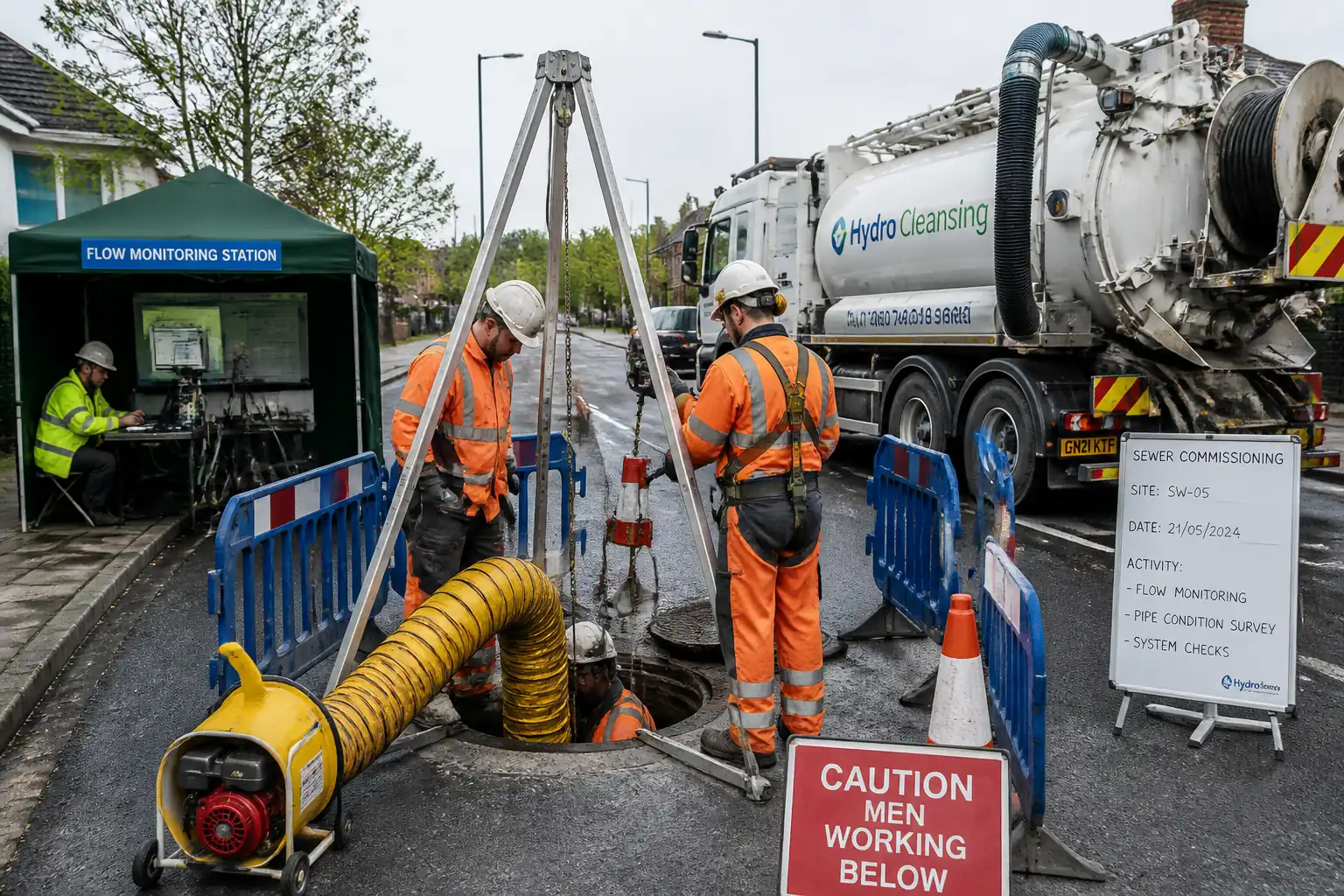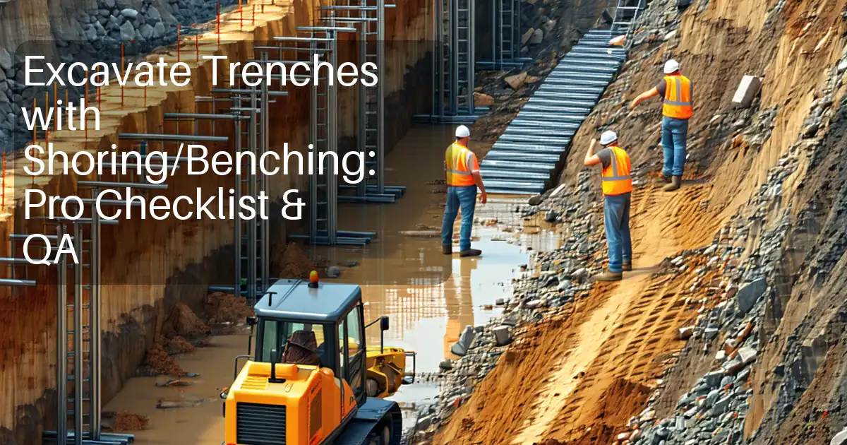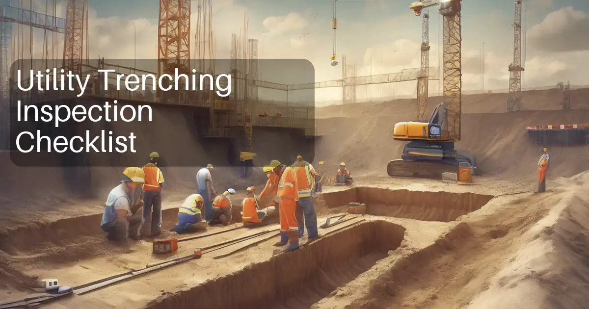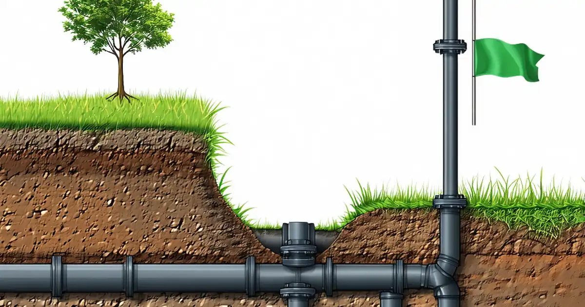

Method Statement: Installation and Removal of Aluminum Hydraulic Shores and Trench Shields for Sewer Pipeline Installations – Method Statement
AI-assisted method statement with matching ITP, PDF download, and Excel export.
More than a static template
Unlike a downloadable Word or PDF template, this method statement is an AI-assisted editable starting point connected directly to a matching Inspection and Test Plan. Every section is structured, project-adaptable, and ready to export.
- AI-assisted drafting — Customize every section with AI for your specific project scope.
- Linked ITP — A matching inspection and test plan is generated alongside the method statement.
- Multiple export formats — Download as a formatted PDF or editable Excel spreadsheet.
- Editable starting point, not a final document — Review, verify, and adjust all content against your project requirements before use.
Static template vs. Quollnet workflow
| Feature | Static template | Quollnet |
|---|---|---|
| Project-specific content | Manual fill-in required | AI-assisted customization |
| Linked ITP | Separate document, no link | Matching ITP included |
| Export formats | Usually PDF only | PDF and Excel |
| Structured sections | Free-form layout | 13 standardized sections |
| Saved to your account | Local file only | Cloud-saved, reusable |
| Content accuracy | You verify everything | AI-assisted, you still verify |
| Cost | Often free but time-intensive | Free to customize and download |
What you can customize
When you save this method statement to your account, every section becomes editable. The following 13 sections are included:
- Scope — Defines the activity and its boundaries.
- References — Standards, specifications, and drawings.
- Responsibilities — Roles and accountabilities.
- Resources — Labour, plant, and equipment summary.
- Materials — Materials and compliance requirements.
- Equipment — Tools and equipment details.
- Prerequisites — Hold points and pre-conditions.
- Method sequence — Step-by-step construction sequence.
- Safety controls — HSE risk controls and PPE.
- Environmental controls — Environmental mitigation measures.
- QA/QC — Quality inspection and test requirements.
- ITP — Inspection and Test Plan table (has its own page).
- Attachments — Referenced drawings and documentation.
Why this method statement is used
This method statement is used to define and communicate the approved procedure for carrying out method statement: installation and removal of aluminum hydraulic shores and trench shields for sewer pipeline installations on site. It ensures the work is planned in advance, the correct resources and controls are in place, and all personnel understand responsibilities, sequence, quality requirements, and safety controls before work begins. It aligns site execution with the documented scope and acceptance expectations.
Who uses this method statement
This method statement is used by contractors, site supervisors, project engineers, QA/QC engineers, HSE officers, consultants, and client representatives. It serves as a shared reference for planning, execution, supervision, inspection, and approval of the activity on site.
When it is prepared and submitted
The method statement is prepared before the work activity starts and submitted as part of the pre-construction documentation package for review and approval.
Who reviews or approves it
The method statement is usually submitted to the client representative, consultant, resident engineer, or project management consultant for review and approval before the work commences.
Important approval note
This method statement is an AI-assisted editable starting point, not a pre-approved document. Before use on any project, all content must be reviewed and approved by the relevant parties (superintendent, principal contractor, or client representative) in accordance with your contract and project quality plan.
For example: if your specification requires a departure from a referenced standard, that departure must be documented and approved separately — this method statement will not capture that automatically. Always verify against your applicable drawings, specifications, and regulatory requirements.
Method statement content
Scope
Work Summary
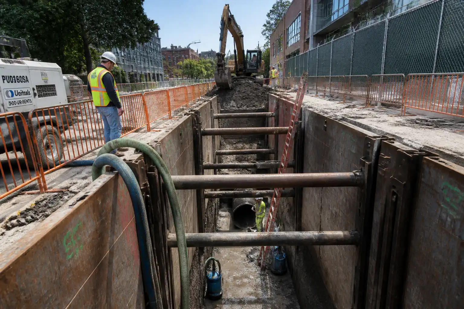
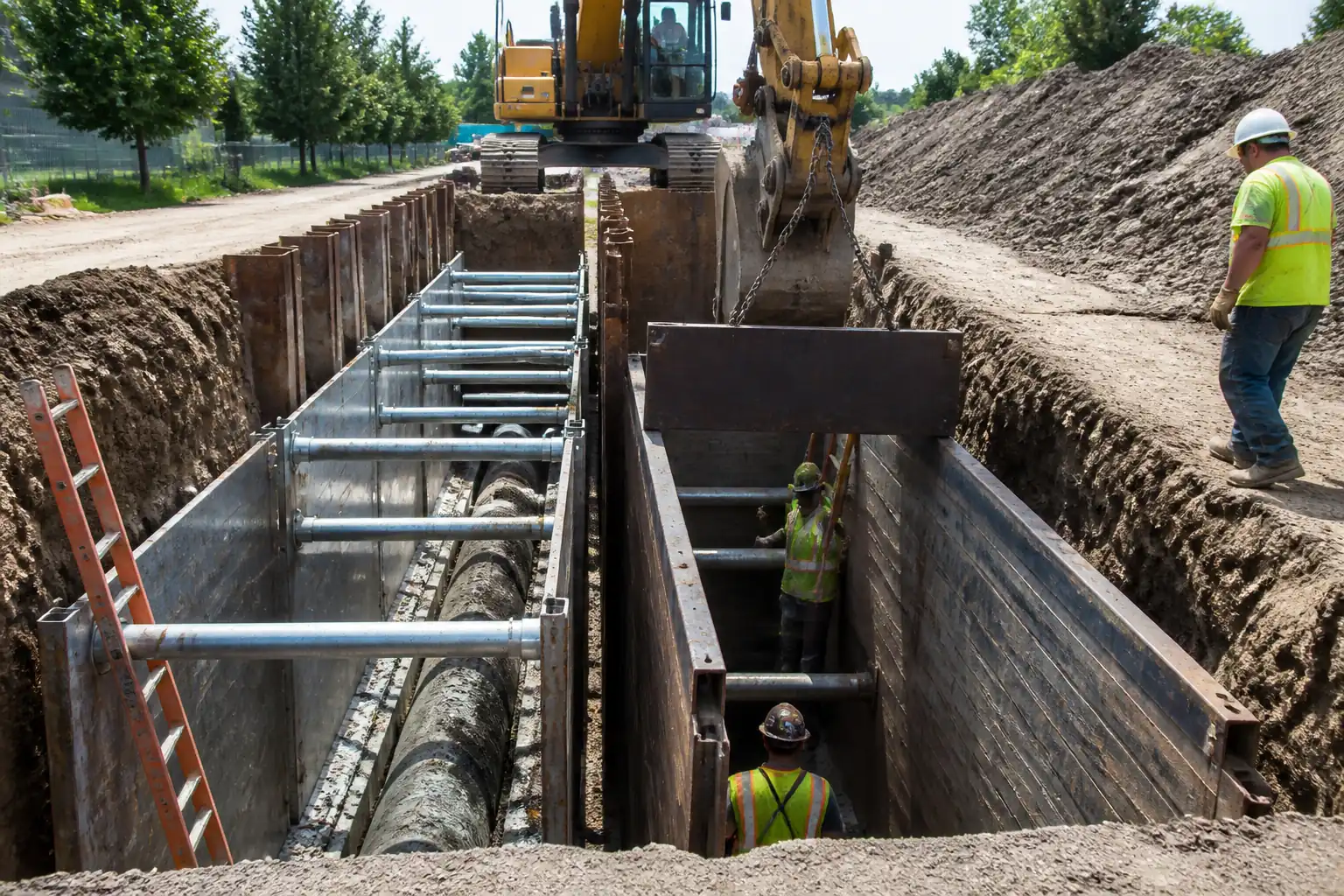
This method covers planning, installation, inspection, use, and removal of aluminum hydraulic shores (AHS) and trench shields (trench boxes) for sewer pipeline trenching works, including staged excavation, dewatering interfaces, capacity verification against ground conditions, worker safe zones, and extraction sequences during backfill.
Objectives
- Provide effective temporary protection for workers in trenches for sewer pipeline installation.
- Ensure shoring/shield design capacities conform to competent design/manufacturer’s tabulated data (MTD).
- Define precise assembly, inspection, pressure control, and sequencing.
- Define safe zones, access/egress, and exclusion areas.
- Control removal (extraction) during backfilling and compaction without loss of trench stability.
Limits/Interfaces
- Applies to open-cut trenches typically 1.5–6.0 m depth [Verify per project specifications].
- Soil classification and groundwater conditions to be verified prior to use.
- Interfaces with dewatering, pipe bedding/laying, compaction testing, traffic management, and confined space entry when connecting to live sewers.
Out of Scope
- Permanent works design of pipelines.
- Slurry walls, soldier piles/lagging, sheet piles, and steel hydraulic bracing (unless separately detailed).
- Deep excavations requiring engineered struts/walers beyond AHS/box capability.
References
| Document Type | Reference / Number | Revision | Notes |
|---|---|---|---|
| Code/Regulation | USA OSHA Subpart P | Use equivalent national regs where applicable [Verify per project HSE plan and local regulations]. | |
| MTD | By OEM/PE | Must be current issue, stamped where required. | |
| Standard | BS 5975 | Adapt governance to project TWC/TWS arrangements. | |
| Standard | EN 1997-1 | Use as design basis if EU jurisdiction; otherwise use local geotechnical codes. | |
| ASTM | ASTM | Testing scope per project specifications. | |
| Standard | ASME B30 series | Or ISO 9927/12480 equivalents. |
Responsibilities
| Role | Responsibility | Name / Party |
|---|---|---|
| Project Manager | Approve method; ensure competent personnel; interface management. | Contractor |
| Engineer | Review soil/groundwater; define allowable trench depth, spacing, pressures. | Contractor |
| Competent Person | Conduct pre-shift checks, atmospheric tests as needed, record defects. | Contractor |
| Supervisor | Toolbox talks; coordinate plant and lifting. | Contractor |
| Lifting Supervisor | Ensure certified gear; manage signal communication. | Contractor |
| HSE | Audits; verify PPE; emergency preparedness. | Contractor |
| Independent | Witness hold/witness points per ITP. | Others |
Resources
| Resource Type | Description | Quantity | Remarks |
|---|---|---|---|
| Labor | Licensed operator for trenching and box handling. | As required | |
| Labor | Bedding, pipe placement, jointing within protected zone. | As required | |
| Labor | Soil classification, daily inspections, corrective actions. | 1 per active trench | |
| Labor | Slinging and signaling for shield movement. | 2–3 | |
| Professional | Design/approval of configuration, checks. | As required |
Materials
| Material | Specification / Grade | Quantity | Remarks |
|---|---|---|---|
| Aluminum alloy | ASTM B221 alloy [Verify] | As designed | |
| Steel/Aluminum | Per OEM | As designed | |
| Hydraulic oil | OEM requirement | Sufficient for pumps | |
| Timber/steel | As required | ||
| Granular | Per project | As required |
Equipment
| Equipment | Capacity / Type | Quantity | Inspection Required |
|---|---|---|---|
| Crawler/wheeled excavator | >10–25 t class [Verify] | 1–2 | Yes |
| Hand/air pump | Up to 3000 psi [Verify] | 1 per crew | Yes |
| Rigging | Per WLL | As required | Yes |
| Pumps/wellpoints | Flow per hydrogeology [Verify] | As required | Yes |
| Compactors | As required | Yes | |
| Gas monitor | 1 per crew | Yes | |
| Access | As required | Yes |
Prerequisites
- Permits: Permit-to-Excavate, Permit-to-Load (temporary works), Lift Plan approval, Confined Space Permit if applicable [Verify per project HSE plan and local regulations].
- Utility Clearance: Review as-builts; conduct GPR/EML and trial holes; obtain utility owner clearances.
- Soil & Groundwater: Competent Person to classify soil (Type A/B/C or local system); confirm groundwater level and inflow estimate; arrange dewatering plan if required.
- Design & Capacities: TWE to confirm suitability of AHS/shield system to trench depth, pipe OD, and soil class based on MTD. Define:
- Maximum trench depth per configuration and soil class.
- Horizontal spacing between shores (typ. 1.2–2.4 m) and vertical spacing between shore levels (typ. 0.9–1.5 m) [Verify per MTD].
- Required initial cylinder pressure range (typ. 700–1500 psi) and gauge accuracy ±2% FS [Verify per MTD].
- Trench shield rating (depth vs soil class), maximum permitted box elevation above trench bottom ≤0.6 m.
- Equipment Condition: Inspect AHS rails, cylinders, hoses, couplers; verify trench shield data plate; rigging certification; pump gauge calibration (≤12 months).
- Site Controls: Traffic management plan; spoil/plant setback; edge protection; egress ladders at ≤7.5 m spacing; lighting for low visibility.
- Briefing: Task-specific TBT covering collapse hazards, pressurized systems, safe zones, emergency rescue.
- Emergency Preparedness: Rescue plan; retrieval tripod/winch where confined space risk; first aid; emergency contacts.
- Environmental Controls: Silt/turbidity control for dewatering discharge; spill kits; noise and dust measures.
Method Sequence
| Step | Activity | Description | Responsibility | Inspection / Hold Point |
|---|---|---|---|---|
| 1 | Site establishment and survey | Set out trench alignment and depth; mark utilities; establish access/egress and exclusion zones. | Site Supervisor | HSE check of barriers and signage |
| 2 | Soil classification and groundwater check | Competent Person classifies soil and notes groundwater. Adjust method (shoring vs shields) accordingly. | Competent Person | Visual/manual tests; review lab data |
| 3 | Dewatering (if required) | Install wellpoints or sump pumps; start discharge to treatment/sediment controls. | Supervisor | Flow and drawdown check |
| 4 | Initial excavation | Excavate to first shore level depth keeping walls stable; maintain spoil ≥0.6 m from edge; plant setback per TWE. | Excavator Operator | Slope/verticality check; edge stability |
| 5 | Install first level of aluminum hydraulic shores | From surface, place rails against trench walls; insert hydraulic cylinders; connect pump; gradually pressurize to initial set pressure per MTD; fit safety pins/locks; verify gauge reading at each shore. | Shoring Crew | Pressure gauge reading; leak check |
| 6 | Progressive excavation and additional shores | Excavate below first level up to next planned level; install additional shores at vertical spacing per MTD; ensure bottom of trench not >0.6 m below lowest installed shore. | Shoring Crew | Spacing and plumb check |
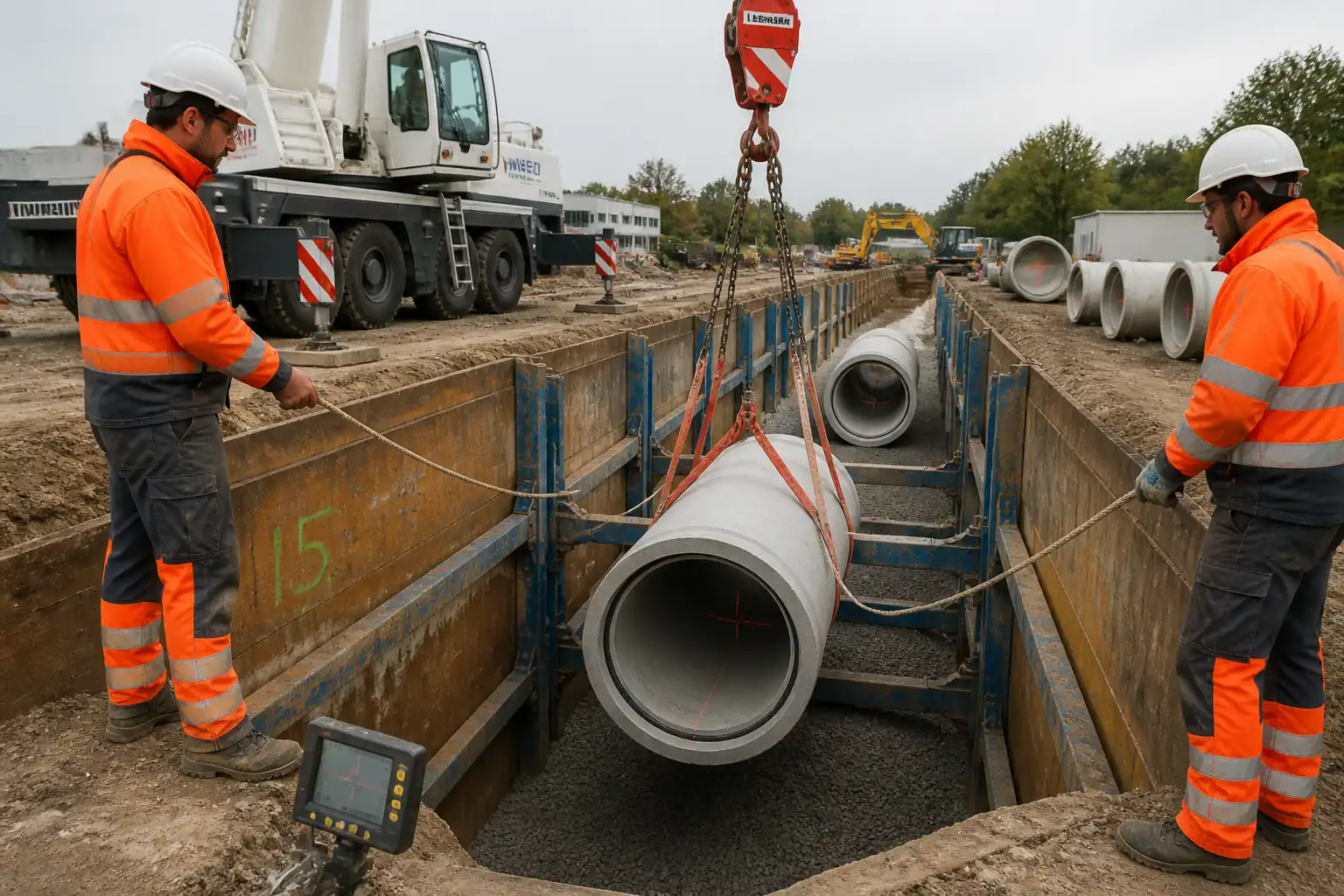
| 7 | Alternative/combined method – Trench shield placement | Rig and lower shield using excavator and certified rigging; set on firm base or pads; ensure bottom gap ≤0.6 m; install/adjust spreaders to required clear width. | Lifting Supervisor | Rigging and data plate check |
| 8 | Define and enforce worker safe zones | Workers to remain inside shield or within the lines of installed shores. Strictly no entry between shield exterior and trench wall. Ladders within 7.5 m; keep loads off box top; exclusion during moves. | Supervisor | Behavioral safety checks |
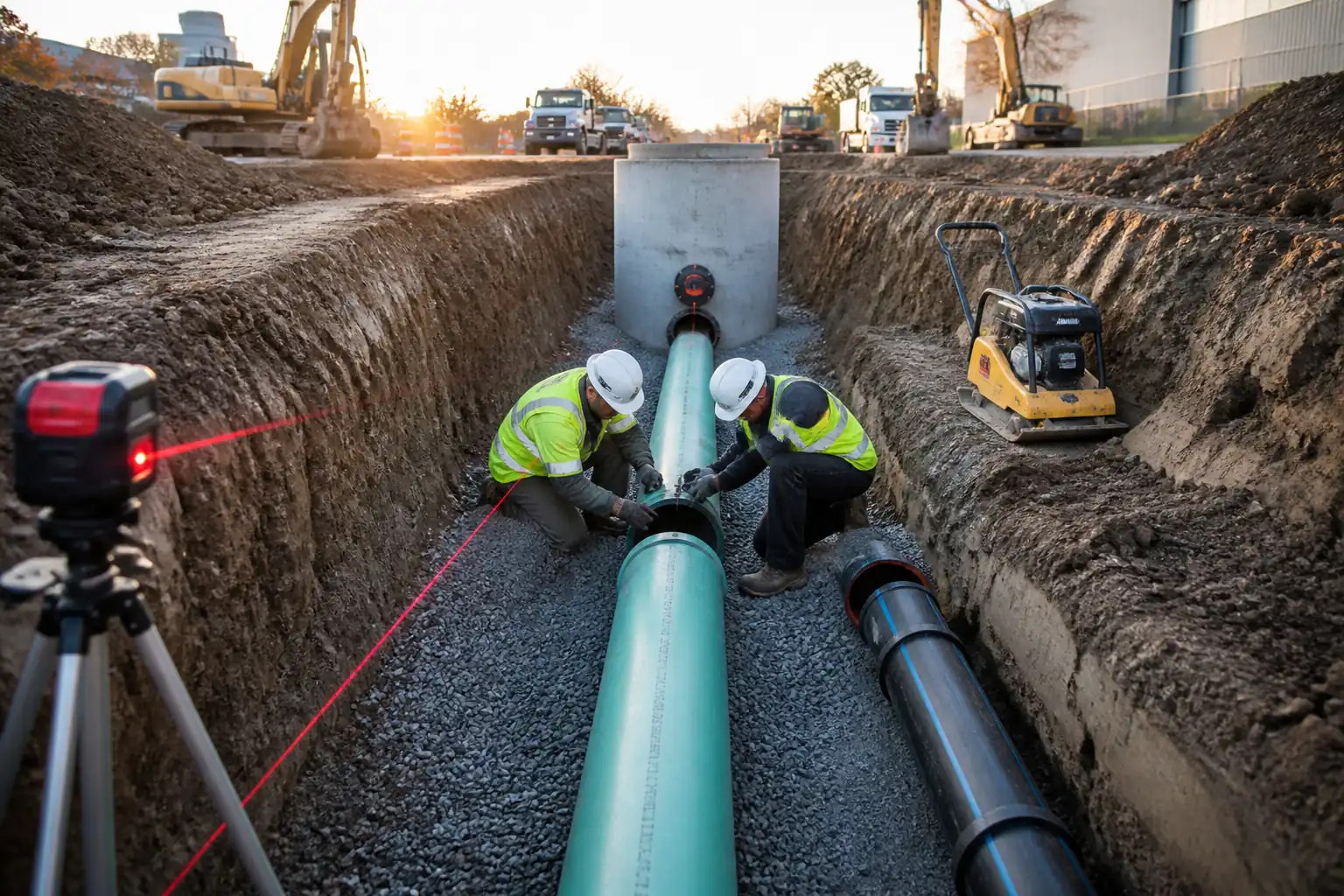
| 9 | Pipe bedding and laying | Place and screed bedding to thickness per spec; set pipe to line/level; joint per pipe spec; inspect before covering. | Pipe Crew | Level/grade check; joint inspection |
| 10 | Relocating trench shield (leapfrogging) | Backfill around pipe to mid-height of the box, compact; ensure no one in box; slightly lift (0.15–0.30 m) and drag/pull forward; reset on firm base; recheck gap ≤0.6 m. | Lifting Supervisor | Box movement control |
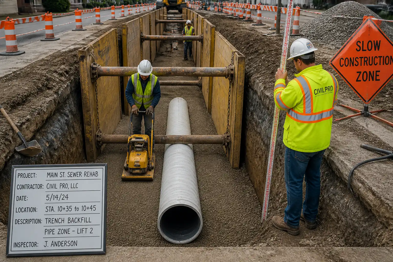
| 11 | Backfill and compaction sequence with AHS removal | Stage backfill in lifts (typically 150–300 mm). Sequence: compact up to just below the lowest shore; bleed pressure slowly and remove the lowest shore; fill/compact to the next shore elevation; repeat upward until top shore removed; final backfill and surface reinstatement. | Supervisor/Shoring Crew | Density tests; visual compaction |
| 12 | Extraction of trench shield during final backfill | With no personnel in trench, backfill to mid-height; lift box 0.3–0.6 m; continue backfilling to near top; fully lift out only when trench is stable and compacted to safe height; maintain exclusion zone. | Lifting Supervisor | Ground bearing/settlement check |
| 13 | Daily and event-driven inspections | Competent Person inspects protective systems daily, after rain, dewatering changes, or impacts; reclassify soil if conditions change. | Competent Person | Formally record inspection |
| 14 | Demobilization and records | Remove remaining equipment; reinstate surfaces; compile records, permits, inspection logs, and as-built data. | Project Engineer | Handover inspection |
Health & Safety Controls
Task-specific hazards and controls
- Hazard: Trench wall collapse/cave-in.
- Likely consequence: Burial/asphyxiation, serious injury, fatality.
- Engineering/procedural control: Use AHS or shield per MTD; maintain bottom gap ≤0.6 m; install shores top-down and remove bottom-up while backfilling; keep surcharge (spoil/plant) set back ≥0.6 m from edge and further as directed by TWE; daily inspections by Competent Person.
- Required PPE: Safety helmet with chin strap, boots with steel toe/midsole, gloves, hi-vis, eye protection.
- Collective preventive measure: Physical barriers/edge protection; exclusion zones; Permit-to-Load.
-
Inspection/permit/supervision: Daily inspection form; TWE approval; stop work after rain or ground change until re-inspection.
-
Hazard: Underground utility strike.
- Likely consequence: Electrocution, explosion, flooding.
- Control: Utility survey (GPR/EML), trial holes, no mechanical excavation within tolerance zone; use insulated tools; liaison with utility owners.
- PPE: Dielectric gloves for electrical work, arc-rated PPE if required.
- Collective: Marked corridors, spotter.
-
Inspection/permit: Permit-to-Excavate; utility plans on site.
-
Hazard: Pressurized hydraulic failure/jet injection.
- Consequence: Puncture wounds, eye injury, sudden loss of support.
- Control: Use rated hoses/couplers; stand clear of couplings while pressurizing; pressurize gradually; install safety pins; follow OEM pressure limits.
- PPE: Face shield/safety goggles, gloves.
- Collective: Exclusion during pressure tests.
-
Inspection/permit: Gauge calibration; hose inspection each shift.
-
Hazard: Lifting operations (lowering/moving trench shields).
- Consequence: Crushing/struck-by, overturning.
- Control: Lift plan; certified rigging; banksman control; no personnel beneath suspended loads; use tag lines; check ground bearing capacity.
- PPE: Helmet, gloves, safety boots, hi-vis.
- Collective: Exclusion zones with barriers; spotter.
-
Inspection/permit: Pre-lift checklist; crane/excavator daily inspection.
-
Hazard: Working in/near sewers – hazardous atmospheres (H2S, low O2).
- Consequence: Toxic exposure, asphyxiation.
- Control: 4-gas monitoring before entry and continuous if required; forced ventilation; confined space permit; rescue plan with retrieval system.
- PPE: Gas monitor, harness, respiratory protection if required.
- Collective: Attendant at entry; permit board.
-
Inspection/permit: Confined Space Permit; bump test logs.
-
Hazard: Water ingress/instability due to groundwater.
- Consequence: Boiling, piping, base heave, collapse.
- Control: Dewatering system sized for inflow; standby pump; maintain drawdown; consider base stabilization.
- PPE: As standard; life jacket if near deep water.
- Collective: Sumps barricaded; hoses routed/supported.
-
Inspection/permit: Dewatering monitoring log; environmental discharge permit.
-
Hazard: Falls into trench.
- Consequence: Fall injuries, entrapment.
- Control: Edge protection/guardrails; fencing; crossings with trench plates; lighting for night work.
- PPE: Hi-vis, boots.
- Collective: Controlled access points only.
-
Inspection/permit: Daily barrier checks.
-
Hazard: Pinch/crush during shield movement or shore extraction.
- Consequence: Serious hand/body injury.
- Control: No personnel inside shield during moves; use pull points; remove shores only when compacted to safe level; use release hooks.
- PPE: Impact gloves, eye protection.
- Collective: Exclusion zone with spotter.
-
Inspection/permit: Supervisor authorization before moves.
-
Hazard: Noise/vibration from compactors and plant.
- Consequence: Hearing loss, hand-arm vibration syndrome.
- Control: Equipment maintenance; task rotation; low-vibration handles.
- PPE: Hearing protection where >85 dBA.
- Collective: Noise barriers where practicable.
-
Inspection/permit: HSE monitoring.
-
Hazard: Adverse weather (rain/heat/cold).
- Consequence: Reduced stability, heat stress.
- Control: Suspend work during heavy rain; re-inspect after; hydration/cooling measures.
- PPE: Weather-appropriate PPE.
- Collective: Weather monitoring.
- Inspection/permit: Competent Person re-inspection after events.
[All controls to be verified per project HSE plan and local regulations]
Environmental Controls
- Dewatering Discharge: Route to settlement tank or approved system; target turbidity ≤50 NTU or per permit [Verify]; inspect outfalls; prevent scour.
- Spill Prevention: Use drip trays under pumps/hydraulics; carry spill kits; biodegradable hydraulic oil preferred in sensitive areas.
- Noise and Dust: Limit idling; wet suppression for dry soils; maintain equipment; restrict night work where possible.
- Waste Management: Collect contaminated absorbents and used hoses as hazardous waste; segregate spoil; manage surplus backfill per project plan.
- Ground Protection: Place mats/timber under shield landing/stacking areas; protect tree root zones where present.
- Watercourse/Drain Protection: Silt fences/berms; no direct discharge to sewers without permit.
- Traffic and Community: Keep haul roads clean; wheel wash if needed; maintain access to properties; notify stakeholders of works schedule.
Quality Assurance / Quality Control
QA/QC Controls
- Documentation: Approved method, MTD, TWE Permit-to-Load, Lift Plan, permits available on site.
- Equipment Inspection: Pre-use inspection of AHS (rails, cylinders, hoses), pump gauge calibration ≤12 months, trench shield data plate and welds free of defects; rigging certifications current.
- Pressure Control: Record target and actual cylinder pressures for each shore at installation. Hold test 10–15 min; acceptable pressure loss ≤5% [Benchmark – Verify per MTD].
- Spacing and Configuration: Confirm horizontal and vertical spacing per MTD; record in daily inspection.
- Shield Placement: Verify bottom gap ≤0.6 m; verticality within ±1 in 6 ft [Benchmark]; spreaders pinned and locked.
- Safe Access/Egress: Ladders within 7.5 m; extend ≥0.9 m above landing; secured.
- Compaction: Test frequency typical 1 test per 50 m per lift or per 500 m³ of placed fill [Verify per project]; target densities: pipe zone ≥95% MDD (ASTM D1557), general backfill 90–95% MDD [Verify].
- Survey: Check invert level and grade (e.g., ±10 mm, ±0.05% grade) [Verify].
- Nonconformance: Record deviations; implement corrective actions (re-pressurize, add shores, recompact).
Attachments
- Risk Assessment / Job Hazard Analysis (JHA)
- Manufacturer’s Tabulated Data (AHS and trench shields)
- TWE design note and Permit-to-Load
- Permit-to-Excavate and utility records (GPR/EML, trial hole photos)
- Lifting Plan and rigging certificates
- Hydraulic pump gauge calibration certificates
- Daily excavation/shoring inspection forms (blank templates)
- Dewatering method and discharge permit
- Confined Space entry plan (if applicable)
- Emergency rescue plan and contact list
- Compaction test reporting templates
This content is a read-only public reference. Download or customize to get an editable version.
ITP preview
The first inspection activities from the linked ITP for Method Statement: Installation and Removal of Aluminum Hydraulic Shores and Trench Shields for Sewer Pipeline Installations:
| Activity | Inspection / Test | Acceptance Criteria | Responsibility | Record |
|---|---|---|---|---|
| Permits and documentation review | All permits approved and in date. | Project Manager / TWC | Permit register / ITP checklist | |
| Utility clearance and trial holes | Utilities located; tolerance zone respected. | Supervisor / Competent Person | Permit-to-Excavate; photos | |
| Soil classification and groundwater assessment | Soil type recorded; dewatering plan implemented if required. | Competent Person | Soil log |
Showing 3 of 13 inspection activities. View full ITP →
Related Inspection and Test Plan
An Inspection and Test Plan (ITP) is available for Method Statement: Installation and Removal of Aluminum Hydraulic Shores and Trench Shields for Sewer Pipeline Installations. The ITP defines the inspection activities, acceptance criteria, hold and witness points, responsible parties, and records required to verify the work described in this method statement.
View the Method Statement: Installation and Removal of Aluminum Hydraulic Shores and Trench Shields for Sewer Pipeline Installations ITP →Frequently asked questions
Continue with related Quollnet resources connected to this method statement.