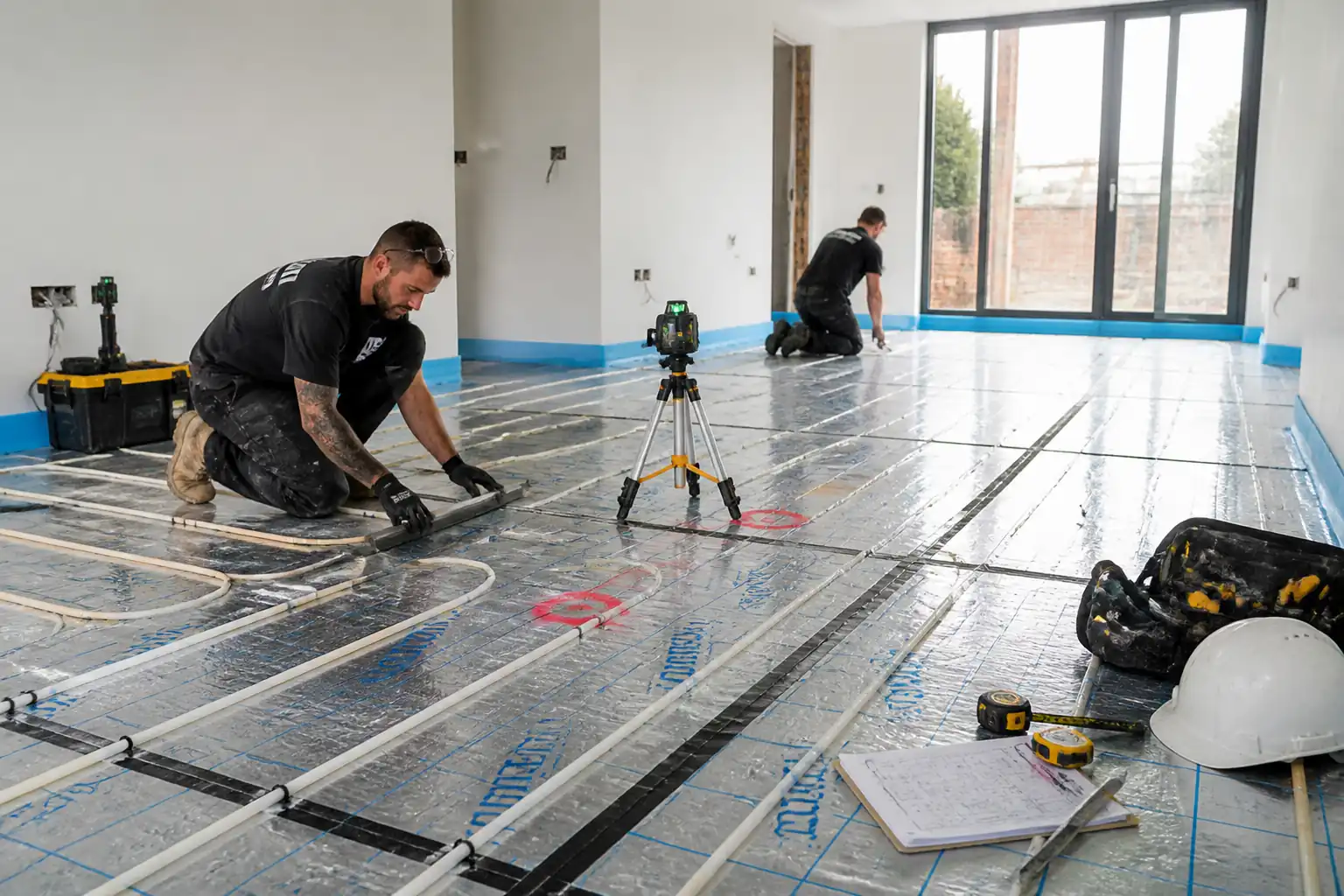

Method Statement: Floating Screed Installation over Thermal/Acoustic Insulation Systems – Method Statement
AI-assisted method statement with matching ITP, PDF download, and Excel export.
More than a static template
Unlike a downloadable Word or PDF template, this method statement is an AI-assisted editable starting point connected directly to a matching Inspection and Test Plan. Every section is structured, project-adaptable, and ready to export.
- AI-assisted drafting — Customize every section with AI for your specific project scope.
- Linked ITP — A matching inspection and test plan is generated alongside the method statement.
- Multiple export formats — Download as a formatted PDF or editable Excel spreadsheet.
- Editable starting point, not a final document — Review, verify, and adjust all content against your project requirements before use.
Static template vs. Quollnet workflow
| Feature | Static template | Quollnet |
|---|---|---|
| Project-specific content | Manual fill-in required | AI-assisted customization |
| Linked ITP | Separate document, no link | Matching ITP included |
| Export formats | Usually PDF only | PDF and Excel |
| Structured sections | Free-form layout | 13 standardized sections |
| Saved to your account | Local file only | Cloud-saved, reusable |
| Content accuracy | You verify everything | AI-assisted, you still verify |
| Cost | Often free but time-intensive | Free to customize and download |
What you can customize
When you save this method statement to your account, every section becomes editable. The following 13 sections are included:
- Scope — Defines the activity and its boundaries.
- References — Standards, specifications, and drawings.
- Responsibilities — Roles and accountabilities.
- Resources — Labour, plant, and equipment summary.
- Materials — Materials and compliance requirements.
- Equipment — Tools and equipment details.
- Prerequisites — Hold points and pre-conditions.
- Method sequence — Step-by-step construction sequence.
- Safety controls — HSE risk controls and PPE.
- Environmental controls — Environmental mitigation measures.
- QA/QC — Quality inspection and test requirements.
- ITP — Inspection and Test Plan table (has its own page).
- Attachments — Referenced drawings and documentation.
Why this method statement is used
This method statement is used to define and communicate the approved procedure for carrying out method statement: floating screed installation over thermal/acoustic insulation systems on site. It ensures the work is planned in advance, the correct resources and controls are in place, and all personnel understand responsibilities, sequence, quality requirements, and safety controls before work begins. It aligns site execution with the documented scope and acceptance expectations.
Who uses this method statement
This method statement is used by contractors, site supervisors, project engineers, QA/QC engineers, HSE officers, consultants, and client representatives. It serves as a shared reference for planning, execution, supervision, inspection, and approval of the activity on site.
When it is prepared and submitted
The method statement is prepared before the work activity starts and submitted as part of the pre-construction documentation package for review and approval.
Who reviews or approves it
The method statement is usually submitted to the client representative, consultant, resident engineer, or project management consultant for review and approval before the work commences.
Important approval note
This method statement is an AI-assisted editable starting point, not a pre-approved document. Before use on any project, all content must be reviewed and approved by the relevant parties (superintendent, principal contractor, or client representative) in accordance with your contract and project quality plan.
For example: if your specification requires a departure from a referenced standard, that departure must be documented and approved separately — this method statement will not capture that automatically. Always verify against your applicable drawings, specifications, and regulatory requirements.
Method statement content
Scope
Overview
This method statement covers the complete installation of floating screeds over thermal and/or acoustic insulation systems, including:
- Substrate verification and damp-proofing interface
- Placement of insulation boards and perimeter flanking/expansion strips
- Installation of separation/vapour control membranes
- Service coordination, including underfloor heating (UFH) systems
- Screed reinforcement (fibres or light mesh) as specified
- Placement, compaction/levelling, finishing, curing and protection
- Movement/expansion, day and bay joints
- QA/QC testing and inspection, including surface regularity (SR), level tolerances, in-situ strength checks (where specified), and moisture content prior to application of final floor finishes
Inclusions
- Cement:sand screeds and calcium sulphate (anhydrite) flow screeds [Verify per project specifications]
- Thermal (e.g., PIR/XPS/EPS) and acoustic (e.g., mineral wool/lamella) insulation systems
- Interface with damp-proof membrane (DPM) or vapour control layer (VCL)
- Temporary protection and access management
Exclusions
- Structural slab construction
- Final floor finishes (vinyl, tile, wood, resin) installation
- Design of acoustic system (values to be verified by acoustic consultant)
Objectives
- Deliver a level, durable screed to specified SR class (typically SR2 unless otherwise stated) and moisture condition suitable for the intended floor finishes, with verified performance over insulation and compliant movement joint strategy.
References
| Document Type | Reference / Number | Revision | Notes |
|---|---|---|---|
| Standard | BS 8204-1 | Surface regularity SR classes; curing; testing; movement joints. | |
| Standard | BS 8204-7 | Guidance for flowing screeds; thickness, joints, curing/drying. | |
| Standard | BS EN 13813 | Material classes (CT, CAF), compressive/flexural strength designations. | |
| Standard | BS EN 13892 | Testing regimes for factory/site mixed screeds. | |
| Standard | BS 8203 | Acceptable RH prior to resilient finishes. | |
| Standard | ASTM F2170 / BS 8203 | Alternative/complimentary moisture tests [Verify per specification]. | |
| Standard | ISO Standards | Management framework references. |
Responsibilities
| Role | Responsibility | Name / Party |
|---|---|---|
| Project Manager | Lead | Main Contractor |
| Site Engineer | Control | Main Contractor |
| HSE Manager | HSE | Main Contractor |
| Quality Manager | QA/QC | Main Contractor |
| Supervisor | Execution | Screeding Subcontractor |
| MEP Coordinator | MEP | MEP Subcontractor |
| Surveyor | Survey | Main Contractor |
Resources
| Resource Type | Description | Quantity | Remarks |
|---|---|---|---|
| Labour | Skilled screeders, finishers, pump operative. | Per bay/shift | |
| Labour | Material handling, cleaning, protection setup. | As needed | |
| Specialist | Pipe layout, pressure test and monitoring during pour. | 1–2 techs |
Materials
| Material | Specification / Grade | Quantity | Remarks |
|---|---|---|---|
| Cementitious screed | Target slump/flow per supplier; w/c per mix design [Verify]. | ||
| Flow screed | Flow spread typically 230–270 mm (Hagerman ring) [Verify]. | ||
| Insulation | Thickness per U-value calc [Verify]. | ||
| Acoustic insulation | Performance per acoustic report [Verify]. | ||
| PE membrane | Laps ≥150 mm, fully taped. | ||
| Edge strip | Continuous; joints taped/staggered. | ||
| Fibres/Mesh | Dosage and lap lengths per supplier/spec [Verify]. | ||
| Primer/Sealer | Per manufacturer. | ||
| Profiles | Width and type per joints schedule [Verify]. |
Equipment
| Equipment | Capacity / Type | Quantity | Inspection Required |
|---|---|---|---|
| Screed pump | Output ≥4–6 m³/h [Verify] | 1 per pour | |
| Laser level | 1 set | ||
| 2 m straightedge | 2–3 | ||
| Hand tools | Set | ||
| Drop hammer | 1 | ||
| RH probes | As required | ||
| UFH tester | 1 |
Prerequisites
- Approvals: Method Statement and ITP approved; material data sheets/SDS submitted and approved.
- Set-out: Datum benchmarks established; finished floor levels (FFL) confirmed; screed thickness allowances verified against door thresholds, drainage falls (if any) and interfaces.
- Substrate readiness: Structural slab cured; DPM/VCL installed and repaired as required; surface free from debris, standing water, oil or sharp protrusions.
- Access and protection: Weather-tight envelope for internal works; temperature 5–30°C; protection from drafts for first 24–72 h; loading restrictions briefed.
- Services: UFH and other services installed, pressure-tested and certified pre-pour; penetrations sleeved; movement joint locations marked.
- Inspections/hold points: Pre-pour inspection of insulation, membranes, perimeter strips and services signed off (Hold Point HP1).
- Plant and calibration: Laser levels, pumps, hygrometers within calibration; backup power/plant arranged.
- HSE: Task-specific RAMS/permits in place [Verify per project HSE plan and local regulations]; toolbox talk completed; COSHH controls for cement/anhydrite confirmed.
Method Sequence
| Step | Activity | Description | Responsibility | Inspection / Hold Point |
|---|---|---|---|---|
| 1 | Substrate verification and cleaning | Sweep/vacuum slab; repair protrusions; confirm DPM presence/continuity where required; rectify sharp edges that could puncture membranes. | Site Engineer / Supervisor | Visual, feel test |
| 2 | Perimeter flanking/edge strip installation | Fix continuous 5–10 mm edge strip to all upstands, columns, and perimeter walls; tape joints and corners; provide height ≥10 mm above finished screed to be trimmed later. | Screeding Subcontractor | Visual continuity check |
| 3 | Insulation board placement | Lay thermal/acoustic boards tightly butted; stagger joints; infill at edges; avoid rocking; install proprietary load-spread layers if specified. Seal around penetrations with compressible sleeves. | Screeding Subcontractor | Straightedge rocking check; gap gauge |
| 4 | Separation membrane (PE) installation | Lay PE membrane over insulation; lap ≥150 mm; tape all laps/penetrations; upturn to walls above FFL; ensure smooth, wrinkle-free surface; avoid punctures. | Screeding Subcontractor | Visual; tape adhesion check |
| 5 | Service coordination and UFH pressure test | Confirm UFH pipe layout against drawings; secure to boards; maintain spacing; perform pressure test (e.g., 6 bar for 24 h) and maintain test pressure during pour [Verify]. Protect manifolds/valves from damage. | MEP Subcontractor / Site Engineer | Gauge check; leak inspection |
| 6 | Movement and day joint setting | Mark joints per drawings: bay size typically ≤40 m², max dimension ≤6 m, aspect ratio ≤2:1; joints at door thresholds, changes in geometry, and around columns. Install profiles where specified. | Site Engineer / Supervisor | Set-out verification |
| 7 | Reinforcement (if specified) | Disperse PP fibres at specified dosage in mix or place mesh at ~mid-depth on chairs; lap mesh ≥100 mm and tie. | Screeding Subcontractor | Dosage check; mesh support check |
| 8 | Level control setup | Install level pins or tripods using laser to achieve FFL; allow for camber and door thresholds; confirm minimum screed thickness: cement:sand floating typically ≥65 mm domestic/≥75 mm commercial; CAF floating typically ≥35–40 mm; with UFH provide cover above pipes typically ≥30 mm cement or 30–35 mm CAF [Verify per spec]. | Site Engineer / Supervisor | Level check with laser |
| 9 | Mixing and delivery | Prepare mix per BS EN 13813/manufacturer data. For flow screed, verify flow spread; for cement:sand, verify workability (ball/hand test) without segregation. Maintain batch traceability. | Screeding Subcontractor | Visual; flow ring test (CAF) |
| 10 | Placement and compaction | Discharge onto membrane; avoid displacement of insulation/UFH; for CAF, dapple in two directions; for cement:sand, compact and level to pins using straightedge and float. | Screeding Subcontractor | Visual; monitor UFH pressure |
| 11 | Finishing and SR control | Close surface using float/trowel (cement); avoid over-trowelling CAF. Check SR progressively using 2 m straightedge. | Screeding Subcontractor | 2 m straightedge spot checks |
| 12 | Curing and early-age protection | Cement:sand: cover with PE sheeting for min 3–7 days, prevent rapid drying; maintain temp ≥5°C, avoid drafts. CAF: do not wet cure; allow controlled ventilation after initial set as per supplier. Restrict traffic for 24–72 h; no heavy loads until design strength. | Screeding Subcontractor | Daily protection check |
| 13 | Post-cure QA checks (SR, level, thickness) | After sufficient set, measure SR across grid (min 1 test per 20 m², ≥10 tests per area [Verify]); check levels vs FFL; verify minimum thickness at penetrations/edges. | Site Engineer / QA | 2 m straightedge; level survey |
| 14 | In-situ strength/indentation (if specified) | BRE screed tester or BS EN 13892 method at representative locations (avoid UFH zones). | QA / Independent tester | Test execution |
| 15 | Drying and moisture verification | Allow drying per thickness and environment; perform in-situ RH (ASTM F2170/BS 8203) or CM test as specified before finishes. | QA / Finishes trade | Probe calibration; hole conditioning |
| 16 | Handover and protection | Install temporary protection (breathable where required); mark bay boundaries and load limits; issue handover pack with QA results. | Main Contractor / Screeding Subcontractor | Visual; signage check |
Safety Controls
Principal Task-Specific Hazards and Controls
- Hazard: Manual handling of cement bags, insulation boards, and profiles.
- Likely consequence: Musculoskeletal injuries.
- Engineering/procedural control: Use mechanical aids (trolleys, hoists); palletize near point of use; team lifts with weight limits posted.
- Required PPE: Safety gloves, safety footwear, back support as needed.
- Collective preventive measure: Material laydown plan to minimize carries; clear access routes.
-
Inspection/permit/supervision: Supervisor checks handling plan; periodic HSE inspections.
-
Hazard: Silica/cement dust during mixing and cutting insulation.
- Likely consequence: Respiratory irritation, long-term lung disease; eye injury.
- Engineering/procedural control: Use pre-packed mixes where possible; on-tool extraction; damp-down cutting area; designated cutting zone.
- Required PPE: FFP2/FFP3 RPE, safety goggles/face shield, gloves.
- Collective preventive measure: Local exhaust ventilation; enclose mixing station.
-
Inspection/permit/supervision: COSHH assessment; equipment PAT and extraction checks.
-
Hazard: Wet cement/anhydrite contact (alkaline burns).
- Likely consequence: Skin burns, dermatitis.
- Engineering/procedural control: Avoid direct contact; provide hand-wash and neutralizing wipes; immediate decontamination procedures.
- Required PPE: Alkali-resistant gloves, long sleeves, waterproof knee pads/trousers.
- Collective preventive measure: Work-rest-wash stations; barrier creams available.
-
Inspection/permit/supervision: COSHH briefing; first-aid kit and eyewash available; supervision to enforce PPE.
-
Hazard: Slips on PE membrane and wet screed.
- Likely consequence: Falls, fractures.
- Engineering/procedural control: Use anti-slip overshoes; limit personnel on membrane; install temporary walkways/boards.
- Required PPE: Slip-resistant boots, overshoes.
- Collective preventive measure: Exclusion zones with barriers.
-
Inspection/permit/supervision: Supervisor to control access; daily housekeeping inspections.
-
Hazard: Pressurized UFH system during pour.
- Likely consequence: Hose/piping failure leading to spray, slips, or injury.
- Engineering/procedural control: Maintain and monitor pressure per specification; protect manifolds; keep personnel clear of manifolds; relief valves functional.
- Required PPE: Eye protection, gloves.
- Collective preventive measure: Barriers/signage around manifolds.
-
Inspection/permit/supervision: Valid UFH pressure test certificate; supervisor monitors gauges hourly.
-
Hazard: Noise and vibration from pumps and mixers.
- Likely consequence: Hearing damage, hand–arm vibration.
- Engineering/procedural control: Maintain equipment; reduce run-time; job rotation for vibrating tools.
- Required PPE: Hearing protection (SNR per site noise survey), anti-vibration gloves.
- Collective preventive measure: Acoustic enclosures where practicable.
-
Inspection/permit/supervision: Noise risk assessment; HAVS records.
-
Hazard: Knife cuts while trimming edge strips and membranes.
- Likely consequence: Lacerations.
- Engineering/procedural control: Use safety knives with auto-retract; cut away from body; cutting mat/straightedge.
- Required PPE: Cut-resistant gloves, long sleeves.
- Collective preventive measure: Blade disposal bins.
-
Inspection/permit/supervision: Supervisor tool checks; training records.
-
Hazard: Trips from hoses, profiles, and level pins.
- Likely consequence: Sprains, falls onto wet screed.
- Engineering/procedural control: Route hoses along perimeters; secure profiles; remove protruding pins promptly.
- Required PPE: Safety footwear with toe protection.
- Collective preventive measure: Cable/pipe ramps; housekeeping regime.
-
Inspection/permit/supervision: Pre-pour walk-down; ongoing supervisor patrol.
-
Hazard: Confined/poorly ventilated spaces (CAF drying emissions minimal but ventilation required).
- Likely consequence: Dizziness, poor air quality.
- Engineering/procedural control: Ensure background ventilation post-initial set; avoid solvent-based products.
- Required PPE: As required by air quality assessment.
- Collective preventive measure: Mechanical ventilation if needed.
-
Inspection/permit/supervision: Air quality/ventilation checks [Verify per project HSE plan and local regulations].
-
Hazard: Electrical hazards from pumps/cords in wet environment.
- Likely consequence: Electric shock.
- Engineering/procedural control: 110 V tools or RCD protection; route cables above wet zones; regular PAT.
- Required PPE: Dielectric gloves where applicable.
- Collective preventive measure: Dedicated power distribution boards.
- Inspection/permit/supervision: Electrical permit/authorization; daily pre-use checks.
Environmental Controls
- Dust and air quality: Use sealed mixing systems and on-tool extraction; damp down cutting area; avoid outdoor dust release near receptors.
- Noise: Schedule high-noise activities within permitted hours; use acoustic screens; maintain equipment to minimize noise.
- Waste management: Segregate packaging, offcuts, and surplus materials; recycle clean insulation offcuts where possible; dispose of contaminated waste via licensed carriers.
- Washout/alkaline water: Collect cementitious washout/water in dedicated containers; neutralize before disposal; prohibit discharge to drains [Verify per local regulations].
- Spills: Spill kits for admixtures/primers; protect drains with covers; report and clean immediately.
- VOCs and products: Select low-VOC primers/sealers; follow manufacturer’s guidance to avoid over-application.
- Energy and materials: Optimize bay planning to reduce waste; accurate quantity take-off; return unopened product.
- Storage: Keep insulation dry and off-ground; protect screed binders from moisture ingress; avoid UV degradation of PE membranes.
- Complaints and monitoring: Maintain an environmental log; respond to neighbor complaints swiftly with mitigations.
QA/QC
Key QA/QC Controls
- Materials verification: Check delivery tickets for screed class per BS EN 13813 (e.g., CT-C20-F4 or CA-C20-F4) [Verify per specification]. Confirm insulation grade/compressive strength and thickness.
- Calibration: Laser level, hygrometers, and BRE tester within calibration period; retain certificates.
- Thickness control: Confirm minimum screed thickness at room perimeters, around services, and mid-bay against level pins and surveyed checks.
- Surface Regularity (SR): Test with 2 m straightedge per BS 8204 across a grid: typical frequency 1 test per 20 m² (min 10 tests per area) [Verify]. Acceptance per specified SR class: SR1 ≤3 mm; SR2 ≤5 mm; SR3 ≤10 mm.
- Level tolerance: Verify against FFL benchmarks; typical acceptance ±5 mm local, ±10 mm overall unless otherwise specified [Verify per project specifications].
- In-situ strength/indentation (if specified): Test using BRE screed tester per BS 8204/BS EN 13892-4. Acceptance per specified ISCR category [Verify].
- Moisture condition before finishes: Test using in-situ RH (ASTM F2170/BS 8203) or CM method. Typical acceptance: resilient finishes ≤75% RH; timber ≤65% RH; for CAF screeds ≤0.5% CM (adhesive-specific) [Verify].
- Jointing: Verify movement/bay joints installed at approved locations; profiles true and secure; joints carried through finishes where required.
- UFH: Pressure test certificates pre-pour; confirm pipe cover thickness and no floating/displacement during pour.
- Records: ITP sign-offs, checklists, test reports, batch/delivery tickets, calibration certificates, as-built level surveys, photos, NCRs and corrective actions.
Hold/Witness Points
- HP1 (Hold): Pre-pour inspection of insulation, membranes, edge strips, and joint set-out.
- HP2 (Hold): UFH pressure test certification prior to pouring and maintained during pour.
- HP3 (Hold): Moisture acceptance testing before release to finishes trade.
- W1 (Witness): Flow spread/workability checks at start and at frequency defined in ITP.
- W2 (Witness): SR and level survey post-cure.
Attachments
- Screed manufacturer data sheets and Safety Data Sheets (SDS)
- Insulation product approvals and compressive strength declarations
- UFH layout drawings and pressure test certificates
- Movement joint layout drawings
- Pre-pour inspection checklist (HP1)
- Flow/workability test log (W1)
- SR and level survey templates (W2)
- Moisture test certificates (HP3)
- Calibration certificates (laser, hygrometers, BRE tester)
- Daily pour and curing logs
- Nonconformance and corrective action forms
This content is a read-only public reference. Download or customize to get an editable version.
ITP preview
The first inspection activities from the linked ITP for Method Statement: Floating Screed Installation over Thermal/Acoustic Insulation Systems:
| Activity | Inspection / Test | Acceptance Criteria | Responsibility | Record |
|---|---|---|---|---|
| Substrate and DPM verification | Visual inspection; DPM continuity check | Clean, sound substrate; DPM/VCL present and intact where specified; no standing water. | Site Engineer / QA | Pre-pour checklist; photos |
| Perimeter strip installation | Continuity and height check | Continuous 5–10 mm strip; no acoustic bridges; height exceeds FFL by ≥10 mm. | QA / Supervisor | Inspection record; photos |
| Insulation board placement | Gaps/rocking check; grade verification | No gaps >3 mm; no rocking >1 mm; board grade/thickness per approved submittal. | QA / Site Engineer | MIR; delivery tickets; photos |
Showing 3 of 14 inspection activities. View full ITP →
Related Inspection and Test Plan
An Inspection and Test Plan (ITP) is available for Method Statement: Floating Screed Installation over Thermal/Acoustic Insulation Systems. The ITP defines the inspection activities, acceptance criteria, hold and witness points, responsible parties, and records required to verify the work described in this method statement.
View the Method Statement: Floating Screed Installation over Thermal/Acoustic Insulation Systems ITP →