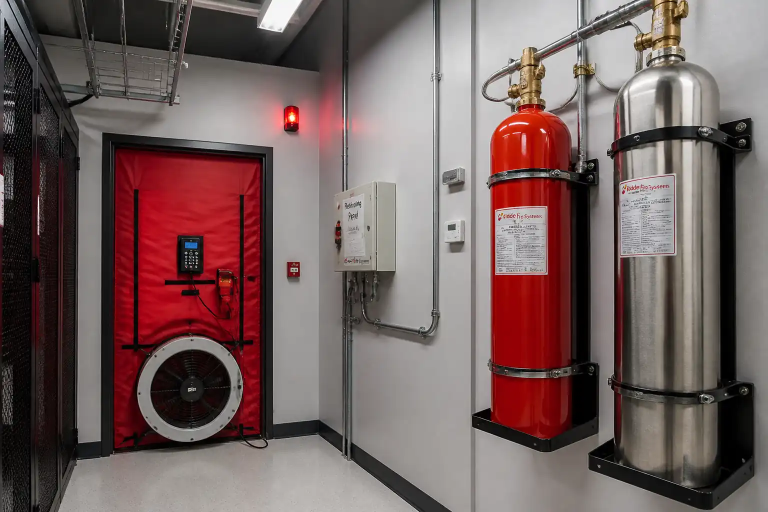

Method Statement – Commissioning of Gaseous Fire Suppression Systems (FM‑200 / Novec 1230) – Method Statement
AI-assisted method statement with matching ITP, PDF download, and Excel export.
More than a static template
Unlike a downloadable Word or PDF template, this method statement is an AI-assisted editable starting point connected directly to a matching Inspection and Test Plan. Every section is structured, project-adaptable, and ready to export.
- AI-assisted drafting — Customize every section with AI for your specific project scope.
- Linked ITP — A matching inspection and test plan is generated alongside the method statement.
- Multiple export formats — Download as a formatted PDF or editable Excel spreadsheet.
- Editable starting point, not a final document — Review, verify, and adjust all content against your project requirements before use.
Static template vs. Quollnet workflow
| Feature | Static template | Quollnet |
|---|---|---|
| Project-specific content | Manual fill-in required | AI-assisted customization |
| Linked ITP | Separate document, no link | Matching ITP included |
| Export formats | Usually PDF only | PDF and Excel |
| Structured sections | Free-form layout | 13 standardized sections |
| Saved to your account | Local file only | Cloud-saved, reusable |
| Content accuracy | You verify everything | AI-assisted, you still verify |
| Cost | Often free but time-intensive | Free to customize and download |
What you can customize
When you save this method statement to your account, every section becomes editable. The following 13 sections are included:
- Scope — Defines the activity and its boundaries.
- References — Standards, specifications, and drawings.
- Responsibilities — Roles and accountabilities.
- Resources — Labour, plant, and equipment summary.
- Materials — Materials and compliance requirements.
- Equipment — Tools and equipment details.
- Prerequisites — Hold points and pre-conditions.
- Method sequence — Step-by-step construction sequence.
- Safety controls — HSE risk controls and PPE.
- Environmental controls — Environmental mitigation measures.
- QA/QC — Quality inspection and test requirements.
- ITP — Inspection and Test Plan table (has its own page).
- Attachments — Referenced drawings and documentation.
Why this method statement is used
This method statement is used to define and communicate the approved procedure for carrying out method statement – commissioning of gaseous fire suppression systems (fm‑200 / novec 1230) on site. It ensures the work is planned in advance, the correct resources and controls are in place, and all personnel understand responsibilities, sequence, quality requirements, and safety controls before work begins. It aligns site execution with the documented scope and acceptance expectations.
Who uses this method statement
This method statement is used by contractors, site supervisors, project engineers, QA/QC engineers, HSE officers, consultants, and client representatives. It serves as a shared reference for planning, execution, supervision, inspection, and approval of the activity on site.
When it is prepared and submitted
The method statement is prepared before the work activity starts and submitted as part of the pre-construction documentation package for review and approval.
Who reviews or approves it
The method statement is usually submitted to the client representative, consultant, resident engineer, or project management consultant for review and approval before the work commences.
Important approval note
This method statement is an AI-assisted editable starting point, not a pre-approved document. Before use on any project, all content must be reviewed and approved by the relevant parties (superintendent, principal contractor, or client representative) in accordance with your contract and project quality plan.
For example: if your specification requires a departure from a referenced standard, that departure must be documented and approved separately — this method statement will not capture that automatically. Always verify against your applicable drawings, specifications, and regulatory requirements.
Method statement content
Scope
Overview
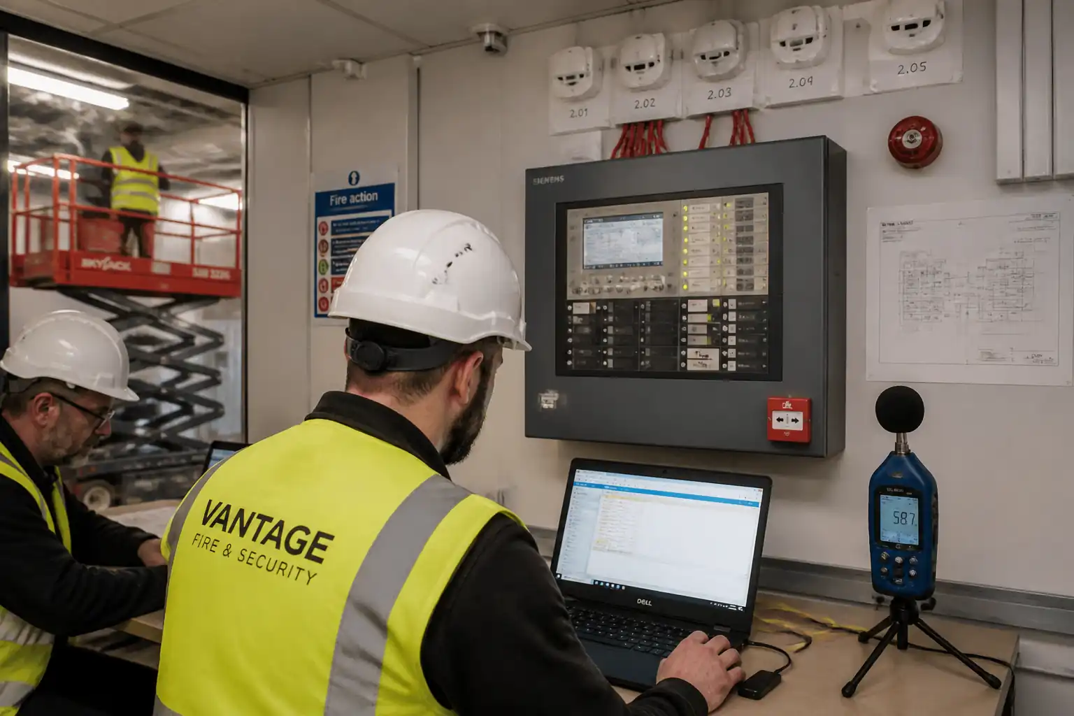
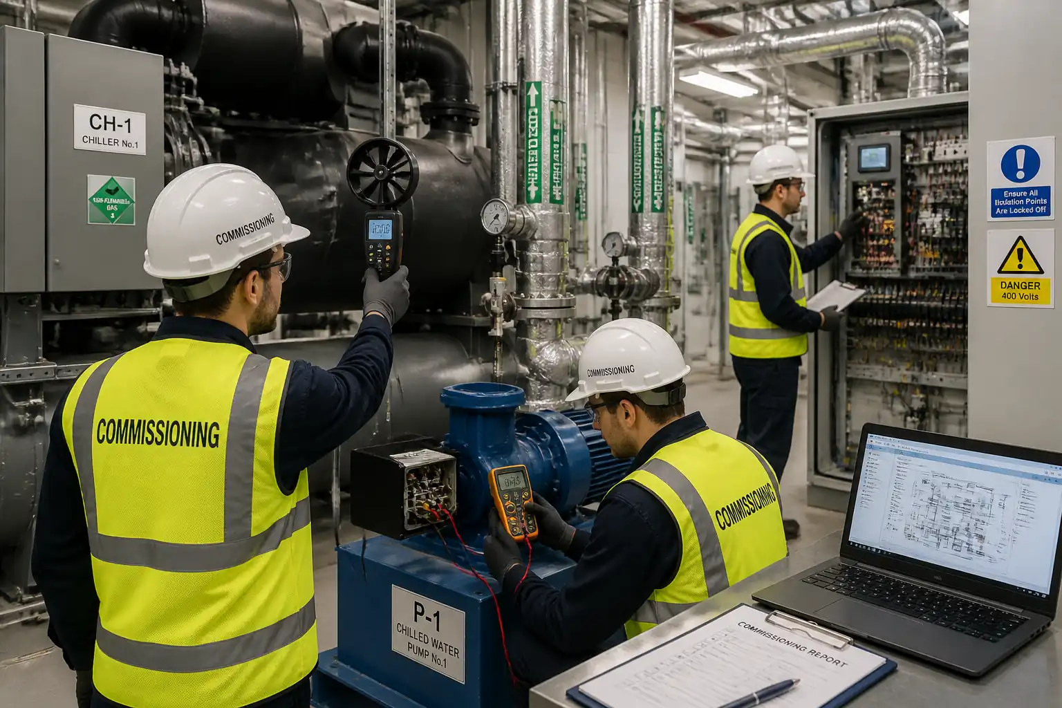
This method statement details the commissioning of gaseous fire suppression systems using FM‑200 (HFC‑227ea) or Novec 1230 (FK‑5‑1‑12). Activities include document verification, safe system isolation, visual/mechanical inspections, cylinder identification and weight/pressure verification, actuator and release circuit testing (without agent discharge), detection logic and abort sequence verification, interfaces testing, and room integrity (door fan) test to confirm design hold time.
Inclusions
- Commissioning of releasing control panel logic per approved Cause & Effect (C&E) matrix.
- Verification of detection zoning, time delay, alarms, manual release, and abort functions.
- Cylinder inventory, hydrostatic date verification, weight and pressure checks.
- Actuation testing: electrical/pneumatic actuators using OEM-compliant test loads and lockout devices (no live discharge).
- HVAC shutdown, dampers, and pressure relief device interlocks testing.
- Room integrity (blower door) testing and reporting.
- Documentation, punch-list closeout, training, and handover.
Exclusions
- Design calculations and hydraulic flow verification (assumed approved prior to commissioning).
- Installation works and pipework pressure testing (completed earlier).
- Live discharge tests (not permitted unless specifically authorized) [Verify per project specifications].
Objectives
- Demonstrate system functionality, safety, and compliance with NFPA 2001 / ISO 14520 / EN 15004, manufacturer requirements, and project specifications.
- Verify predicted hold time meets or exceeds the design requirement (typically ≥10 minutes for halocarbon systems) [Verify per project specifications].
- Deliver complete commissioning records and ITP compliance.
References
| Document Type | Reference / Number | Revision | Notes |
|---|---|---|---|
| Standard | NFPA 2001 (latest) | Use Annex guidance for enclosure integrity procedure. | |
| Standard | ISO 14520 / EN 15004 | Follow OEM-specific provisions where stricter. | |
| Standard | NFPA 72 (latest) | ||
| Standard | ASTM E779 / ISO 9972 | Applied for method; acceptance per NFPA 2001/ISO 14520 hold-time requirement. | |
| Standard | BS EN 12094 | ||
| Standard | IEC 61557 / IEC 61010 | ||
| Manual | OEM-specific | Follow OEM requirements where more stringent than codes. | |
| Contract Docs | Values marked [Verify per project specifications] to be confirmed. |
Responsibilities
| Role | Responsibility | Name / Party |
|---|---|---|
| PM | Approve method/ITP, ensure permits/approvals in place. | Main Contractor |
| Cx Manager | Implements method, manages hold/witness points, reporting. | Main Contractor |
| Specialist | Supervise actuator tests, verify cylinder data, sign OEM checklists. | Vendor/OEM |
| Supervisor | Panel programming upload/backup, loop terminations, interface verification. | Subcontractor |
| HSE | Impairment plan, lockout/tagout (LOTO), atmosphere monitoring if required. | Main Contractor |
| QA/QC | Manage ITP, calibrations, NCR/CAR closeout. | Main Contractor |
| Specialist | Setup blower door, run tests, report hold time. | Approved Agency |
| Engineer/Client | Approve results, punch-list resolution. | Engineer/Client |
Resources
| Resource Type | Description | Quantity | Remarks |
|---|---|---|---|
| Manpower | Commissioning Manager, Fire Systems Specialist, ELV Technicians (2–4), QA/QC Engineer. | 1 team | |
| Manpower | HSE Officer covering live commissioning hours. | 1 | |
| Specialist | Certified operator with calibrated blower door kit. | 1 crew |
Materials
| Material | Specification / Grade | Quantity | Remarks |
|---|---|---|---|
| FM‑200 | OEM | Per design | |
| Novec 1230 | OEM | Per design | |
| Cartridges | As required | ||
| Seals/pins | As required | ||
| Labels | Complete set |
Equipment
| Equipment | Capacity / Type | Quantity | Inspection Required |
|---|---|---|---|
| Up to 300 kg typical | 1 set | ||
| 1 | |||
| 1–2 | |||
| 1 | |||
| 1 set | |||
| 1 | |||
| As required |
Prerequisites
- Approvals: Method statement, ITP, C&E matrix, as-built drawings, and OEM manuals approved by Engineer.
- Documentation available: Design concentration calculations, nozzle schedule, piping isometric, cylinder list, relief vent sizing, HVAC/fire interfaces list.
- PTW and impairment plan approved; notification to stakeholders; evacuation routes briefed [Verify per project HSE plan and local regulations].
- LOTO: Discharge outlets mechanically locked or discharge lines safely isolated per OEM; actuation cartridges pinned/removed and replaced with test devices as applicable. Do not depressurize or disconnect any charged cylinder unless authorized and made safe by OEM.
- Power-on checks of releasing panel completed; battery and charger functional; event logs clear.
- Device installation checked previously: detector spacing, zoning, manual release/abort stations, signage, nozzles orientation, orifice tags, and pipe supports verified compliant.
- Room prepared for integrity test: all penetrations sealed; doors/windows operable; pressure relief dampers installed and set; cable trays/firestopping complete.
- Calibration certificates for measurement instruments verified valid (within 12 months or per project QA).
- Cylinders accessible; lifting aids available; floor protected; cylinder anchoring/brackets installed.
- Coordination: Confirm no co-activities causing openings (e.g., door propping) during door fan test. Ensure HVAC is in the normal protected-room operating mode required by design (shutdown during release as per C&E).
Method Sequence
| Step | Activity | Description | Responsibility | Inspection / Hold Point |
|---|---|---|---|---|
| 1 | Kick-off & Documentation Review | Review approvals, C&E matrix, as-builts, calculations, and OEM procedures. Assign roles and schedule hold/witness points. | Commissioning Manager | Document check |
| 2 | Site HSE Setup & Impairment | Establish barriers, warning signs, and LOTO. Insert safety pins/lockouts on actuators; replace squibs with OEM dummy loads where required. Isolate downstream discharge if OEM method demands. | HSE Officer / Fire Specialist | LOTO verification |
| 3 | Visual & Mechanical Inspection | Check cylinders for damage/corrosion; brackets/straps secure; hydrostatic test date within statutory period [Verify per jurisdiction]. Inspect piping supports, nozzles orientation, orifice identifiers, relief vents, and signage. | QA/QC Engineer / OEM Rep | Physical inspection |
| 4 | Cylinder Pressure Check (Temperature-Corrected) | Record ambient cylinder temperature; compare gauge/pressure transducer to OEM pressure-temperature chart for given superpressurization class (e.g., 25 bar/42 bar). | OEM Rep / Technician | Gauge reading vs chart |
| 5 | Cylinder Weight Verification | Weigh each cylinder assembly using calibrated scale or load cell. Deduct tare to obtain net fill. Compare with nameplate. | OEM Rep / QA/QC | Scale measurement |
| 6 | Release Circuit Integrity (Safe Test) | Isolate live cartridges; connect OEM dummy loads/shunts. Verify circuit continuity and EOL values using DMM within OEM test current limits. Do not megger release circuits. | ELV Supervisor / OEM Rep | Continuity/resistance check |
| 7 | Manual Release Station Test (Simulated) | With discharge inhibited, operate manual pull/release at entrance and local panel. Verify sequence without discharge. | ELV Supervisor | Functional simulation |
| 8 | Abort Function Verification | Activate abort pushbutton during pre-discharge delay. Confirm discharge is inhibited while pressed; timer resets/holds per programmed logic; annunciation maintained. | ELV Supervisor / OEM Rep | Functional test |
| 9 | Detection Logic / Cross-Zone Test | Introduce test smoke/heat per detector type or simulate via panel where allowed. Verify that two-detect (or programmed) condition initiates release sequence and pre-alarms. | Fire Specialist / ELV Supervisor | Functional cause & effect |
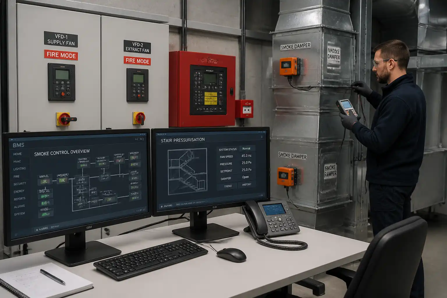
| 10 | Interfaces Verification | Test HVAC shutdown, damper closure, door holders release, EPO if applicable, pressure relief vent operation (non-discharge check), door access control fail-safe. | ELV Supervisor / BMS Technician | Functional interface tests |
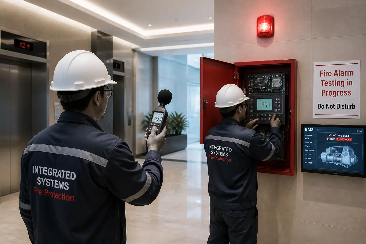
| 11 | Notification Appliances & Signage | Verify strobes, sounders, pre-discharge messages, and signage at entrances. | ELV Supervisor | A/V test |
| 12 | Room Integrity (Door Fan) Test | Install blower door; conduct pressurization/depressurization to 50 Pa. Determine Equivalent Leakage Area and predict hold time using agent properties per NFPA 2001/ISO 14520. | Door Fan Specialist / QA/QC | Blower door test |
| 13 | Actuator Functional Test (No-Discharge) | Using OEM test mode or mechanical lockout, energize electric actuator via panel to verify coil current and response (click/indicator) without opening valve; for pneumatic, verify pilot pressure path with test gauge. | OEM Rep / ELV Supervisor | Actuator simulation |
| 14 | System Restoration | Remove inhibits as authorized, re-install cartridges/pins per OEM, remove lockouts where safe, restore normal mode, clear faults, update impairment register. | Fire Specialist / HSE | Restoration check |
| 15 | Training & Handover | Conduct operator training on release/abort, emergency procedures, maintenance, and impairment process. Submit records and O&M updates. | Commissioning Manager / OEM Rep | Training verification |
Task-Specific Safety Controls
Principal Hazards and Controls
- Hazard: Inadvertent agent discharge (asphyxiation risk, cold burns from rapid discharge).
- Likely consequence: Oxygen displacement; injury; panic; equipment damage.
- Engineering/procedural control: Approved impairment plan; mechanical lockout pins or discharge isolations; replace squibs with OEM dummy loads; use panel inhibit/test mode; restrict access and post warning signs.
- Required PPE: Safety glasses, gloves, long sleeves; hearing protection during A/V tests.
- Collective measure: Area cordoned; spotter at entrance; muster plan briefed.
-
Inspection/permit/supervision: PTW with LOTO; OEM representative or Fire Specialist supervises; sign-off before restoration [Verify per project HSE plan and local regulations].
-
Hazard: High-pressure cylinders (stored energy, projectile hazard if mishandled).
- Likely consequence: Impact injuries, fractures, fatality.
- Engineering/procedural control: Keep cylinders anchored; use rated lifting gear and collars; prohibit valve manipulation; no heating; maintain protective caps.
- PPE: Safety boots, gloves, helmet.
- Collective measure: Exclusion zone during weighing; use trolleys and lift assists.
-
Inspection/permit/supervision: Pre-use inspection of slings/scales; lifting plan if using hoist.
-
Hazard: Electrical shock from control circuits.
- Likely consequence: Electric shock, burns.
- Engineering/procedural control: Isolate control power when terminating; use CAT-rated DMM; prohibit megger on release circuits; follow OEM low-energy testing.
- PPE: Insulated gloves (as required), eye protection.
- Collective measure: Lockable panel covers; test leads with shrouded tips.
-
Inspection/permit/supervision: Electrical PTW; supervisor oversight.
-
Hazard: Door fan test pressure differentials and door slams.
- Likely consequence: Pinch injuries, falls, damage to frames.
- Engineering/procedural control: Secure test frame; communicate before fan ramp; control entry/exit; use door restraints.
- PPE: Gloves, eye protection.
- Collective measure: Barricade and signposting.
-
Inspection/permit/supervision: Specialist procedure; equipment calibration verified.
-
Hazard: Working at height (nozzle/duct device access).
- Likely consequence: Falls, injury.
- Engineering/procedural control: Use compliant mobile platforms; inspect ladders; maintain three-point contact.
- PPE: Safety harness if required, non-slip footwear.
- Collective measure: Spotter and clear floor area.
-
Inspection/permit/supervision: Work at height permit where applicable.
-
Hazard: Noise from alarms/sounders.
- Likely consequence: Hearing damage, startle.
- Engineering/procedural control: Prewarn personnel; stagger tests; limit exposure time.
- PPE: Hearing protection.
- Collective measure: Temporary relocation of non-essential staff.
-
Inspection/permit/supervision: HSE monitoring as required.
-
Hazard: Manual handling of heavy cylinders.
- Likely consequence: Strains, crush injuries.
- Engineering/procedural control: Team lifts; use dollies and hoists; maintain upright handling.
- PPE: Gloves, safety boots.
- Collective measure: Clear pathways and use ramps where needed.
-
Inspection/permit/supervision: Manual handling training verified.
-
Hazard: ESD damage to electronic squibs/boards.
- Likely consequence: Latent device failure.
- Engineering/procedural control: ESD straps/mats; antistatic bags; follow OEM handling.
- PPE: ESD wrist strap as applicable.
- Collective measure: ESD-controlled workstation.
- Inspection/permit/supervision: QA checks of ESD controls.
Environmental Controls
- Agent release prevention: No intentional venting. Use non-discharge test procedures; maintain lockouts and inhibits. Any accidental release to be reported and managed under incident and environmental procedures [Verify per project HSE plan and local regulations].
- GWP considerations: FM‑200 has high GWP; minimize handling and prevent leaks. Novec 1230 has low GWP but still must not be released.
- Cylinder handling: Return unserviceable or partially depleted cylinders to OEM for recovery/recycling. No on-site decanting.
- Waste management: Dispose of tamper seals, packaging, and failed components via approved waste streams. Batteries and electronic waste handled per WEEE/ISO 14001 procedures.
- Noise and vibration: Schedule audible tests to minimize nuisance; notify occupants.
- Energy/air paths during door fan test: Seal temporary openings only with removable materials; restore as-found afterwards.
- Dust/contaminants: Use clean test smoke; protect sensitive IT equipment; housekeeping after works.
- Spill control: Maintain clean, dry area; use mats to protect floors from cylinder bases.
Quality Assurance / Quality Control
- Calibration: Verify current calibration for scales, manometers, DMMs; retain certificates in dossier.
- Identification: Cross-check each cylinder serial number, agent type, net fill, and hydrostatic date against the schedule.
- Traceability: Record ambient temperature, pressure readings, weight readings, and instrument IDs on test sheets.
- Conformance: Compare sequence and timings against approved C&E matrix; document any deviations and corrective actions.
- ITP compliance: Adhere to hold/witness points for impairment setup, cylinder weighing, abort test, and door fan test.
- Punch-list: Log defects with photos; categorize critical/non-critical; re-test after rectification.
- Documentation: Compile integrity test report, functional test records, redlined drawings, panel configuration backup, training attendance, and OEM sign-offs into the handover package.
- Acceptance: Final acceptance contingent upon meeting hold time requirement, successful functional tests with no outstanding critical NCRs, and restoration to normal service.
Attachments
- Pre-functional inspection checklist (cylinders, piping, nozzles, brackets, signage)
- Cylinder pressure-temperature chart (OEM) and weight log sheets
- Release circuit integrity and actuator test forms
- Cause & Effect matrix verification checklist
- Interface test sheets (HVAC, dampers, power shutdown, access control)
- Enclosure Integrity Test (door fan) report template
- Panel configuration backup file and version log
- Training attendance sheet and quick-reference operator guide
- Risk assessment and PTW/LOTO templates
This content is a read-only public reference. Download or customize to get an editable version.
ITP preview
The first inspection activities from the linked ITP for Method Statement – Commissioning of Gaseous Fire Suppression Systems (FM‑200 / Novec 1230):
| Activity | Inspection / Test | Acceptance Criteria | Responsibility | Record |
|---|---|---|---|---|
| Document & Drawing Verification | Check approvals for C&E, as-builts, OEM manuals, calculations. | All current and approved; revisions consistent. | QA/QC Engineer | Pre-test checklist / approvals register |
| Calibration Verification | Check calibration certs for scale, DMM, blower door manometer. | Valid within 12 months or per project; traceable to standards. | QA/QC Engineer | Calibration register copies |
| HSE Setup & Impairment Controls | Verify LOTO, safety pins, inhibits, signage, barriers. | No possibility of discharge; PTW active; controls signed off. | HSE Officer / Cx Manager | PTW; LOTO log; impairment form |
Showing 3 of 16 inspection activities. View full ITP →
Related Inspection and Test Plan
An Inspection and Test Plan (ITP) is available for Method Statement – Commissioning of Gaseous Fire Suppression Systems (FM‑200 / Novec 1230). The ITP defines the inspection activities, acceptance criteria, hold and witness points, responsible parties, and records required to verify the work described in this method statement.
View the Method Statement – Commissioning of Gaseous Fire Suppression Systems (FM‑200 / Novec 1230) ITP →Frequently asked questions
Continue with related Quollnet resources connected to this method statement.