Method Statement: Building Gridline Setting Out and Control Transfer Prior to Excavation, Piling, and Foundation Works – Method Statement
AI-assisted method statement with matching ITP, PDF download, and Excel export.
More than a static template
Unlike a downloadable Word or PDF template, this method statement is an AI-assisted editable starting point connected directly to a matching Inspection and Test Plan. Every section is structured, project-adaptable, and ready to export.
- AI-assisted drafting — Customize every section with AI for your specific project scope.
- Linked ITP — A matching inspection and test plan is generated alongside the method statement.
- Multiple export formats — Download as a formatted PDF or editable Excel spreadsheet.
- Editable starting point, not a final document — Review, verify, and adjust all content against your project requirements before use.
Static template vs. Quollnet workflow
| Feature | Static template | Quollnet |
|---|---|---|
| Project-specific content | Manual fill-in required | AI-assisted customization |
| Linked ITP | Separate document, no link | Matching ITP included |
| Export formats | Usually PDF only | PDF and Excel |
| Structured sections | Free-form layout | 13 standardized sections |
| Saved to your account | Local file only | Cloud-saved, reusable |
| Content accuracy | You verify everything | AI-assisted, you still verify |
| Cost | Often free but time-intensive | Free to customize and download |
What you can customize
When you save this method statement to your account, every section becomes editable. The following 13 sections are included:
- Scope — Defines the activity and its boundaries.
- References — Standards, specifications, and drawings.
- Responsibilities — Roles and accountabilities.
- Resources — Labour, plant, and equipment summary.
- Materials — Materials and compliance requirements.
- Equipment — Tools and equipment details.
- Prerequisites — Hold points and pre-conditions.
- Method sequence — Step-by-step construction sequence.
- Safety controls — HSE risk controls and PPE.
- Environmental controls — Environmental mitigation measures.
- QA/QC — Quality inspection and test requirements.
- ITP — Inspection and Test Plan table (has its own page).
- Attachments — Referenced drawings and documentation.
Why this method statement is used
This method statement is used to define and communicate the approved procedure for carrying out method statement: building gridline setting out and control transfer prior to excavation, piling, and foundation works on site. It ensures the work is planned in advance, the correct resources and controls are in place, and all personnel understand responsibilities, sequence, quality requirements, and safety controls before work begins. It aligns site execution with the documented scope and acceptance expectations.
Who uses this method statement
This method statement is used by contractors, site supervisors, project engineers, QA/QC engineers, HSE officers, consultants, and client representatives. It serves as a shared reference for planning, execution, supervision, inspection, and approval of the activity on site.
When it is prepared and submitted
The method statement is prepared before the work activity starts and submitted as part of the pre-construction documentation package for review and approval.
Who reviews or approves it
The method statement is usually submitted to the client representative, consultant, resident engineer, or project management consultant for review and approval before the work commences.
Important approval note
This method statement is an AI-assisted editable starting point, not a pre-approved document. Before use on any project, all content must be reviewed and approved by the relevant parties (superintendent, principal contractor, or client representative) in accordance with your contract and project quality plan.
For example: if your specification requires a departure from a referenced standard, that departure must be documented and approved separately — this method statement will not capture that automatically. Always verify against your applicable drawings, specifications, and regulatory requirements.
Method statement content
Scope
Overview
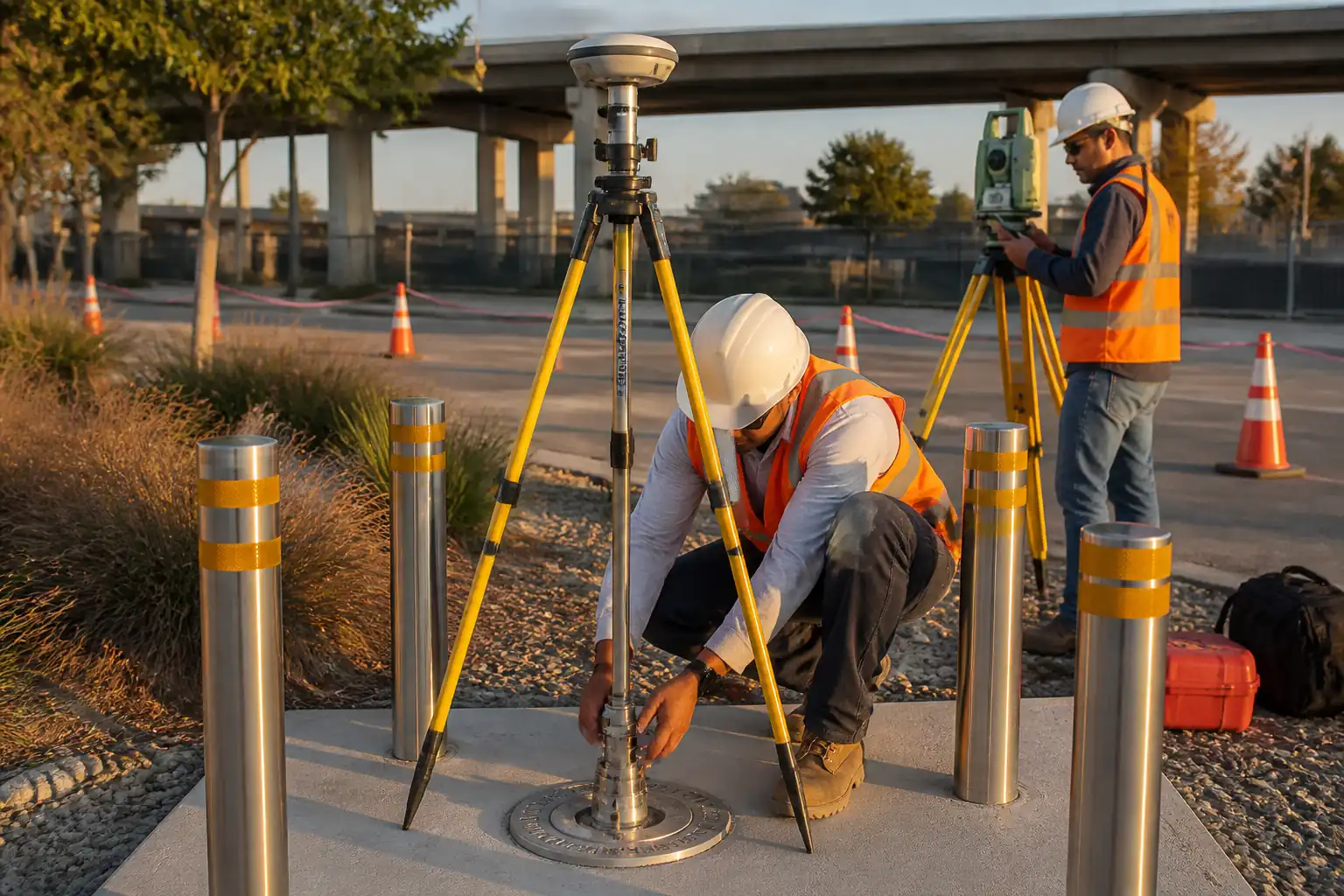
This method covers the complete survey workflow for building gridline setting out works prior to excavation, piling, and foundation construction. It includes verification and establishment of primary/secondary control, transfer of control to working levels, total station operations, dimensional verification, offset marking for excavation and pile locations, independent survey checks, QA/QC inspections, as-built records, and release procedures.
Inclusions
- Review of coordinate reference system, benchmarks (TBMs), and design grid data
- Establishment/verification of primary horizontal and vertical control
- Creation of working (secondary) control network
- Total station setup, orientation, and instrument checks
- Building gridline computation and on-site setting out
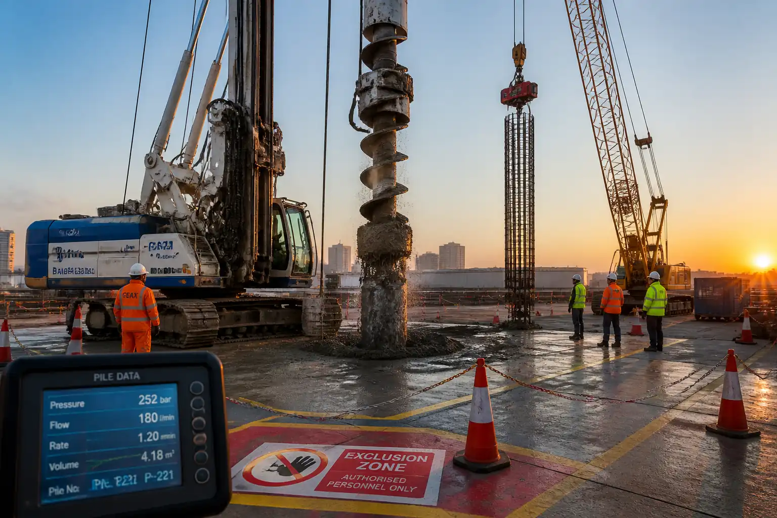
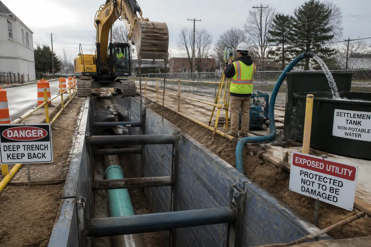
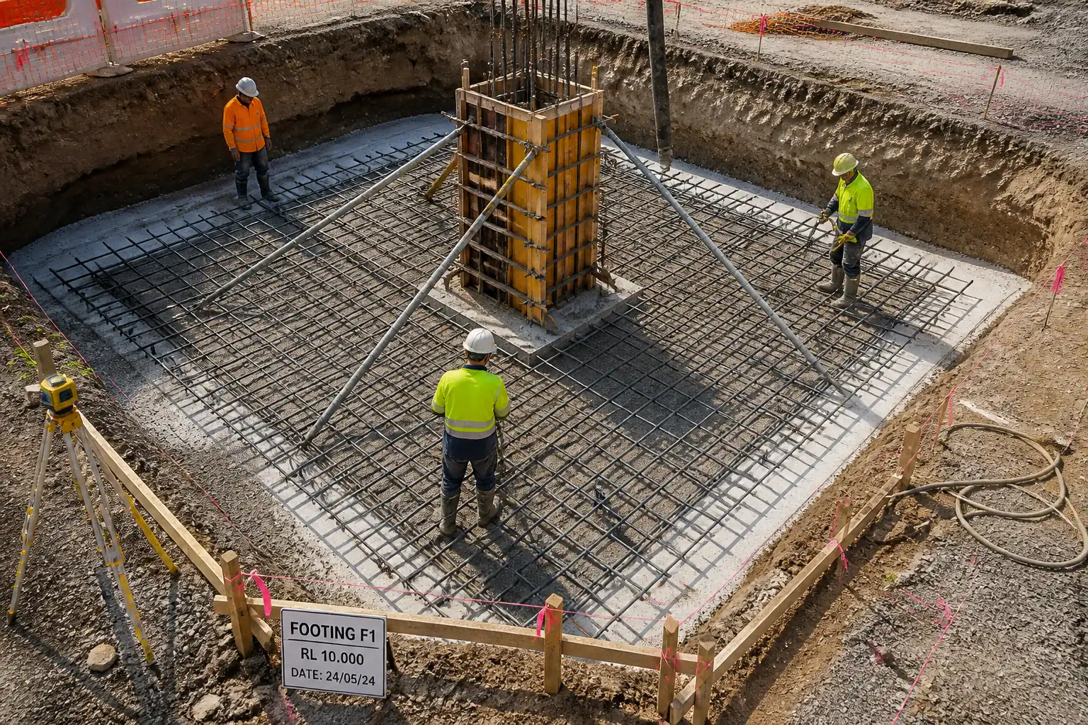
- Offset marking for excavation boundaries, profile boards, and pile set-out
- Transfer of control to basements and elevated floors
- Dimensional verification and tolerances
- Independent survey check (ISC) and ITP hold/witness points
- Deliverables: setting-out reports, control network diagrams, coordinates registers, redlines/as-built
Exclusions
- Topographic surveys beyond work limits (unless specifically instructed)
- Utility detection surveys (refer to separate method; coordinate tie-ins included where provided)
- Temporary works design for edge protection, access platforms, or scaffolding
Key Tolerances [Verify per project specifications]
- Primary horizontal control positional tolerance: ±5 mm to ±10 mm
- Primary vertical control closure: ≤4 mm × √km (digital leveling loop)
- Working/secondary control positional tolerance: ±8 mm
- Gridline position at intersection: ±5 mm (relative to control)
- Gridline on level transfer (storey-to-storey): ≤±6 mm
- Pile set-out positional tolerance: typically ±10 mm (horizontal) and top level ±5 mm
- Excavation offset pegs relative to design cut: ±20 mm (horizontal) and ±10 mm (vertical)
All values are typical benchmarks and must be confirmed against the project specifications and Engineer’s requirements.
References
| Document Type | Reference / Number | Revision | Notes |
|---|---|---|---|
| Standard | ISO 4463 series (latest) | Latest Edition | General framework for setting out and measurement practices |
| Standard | ISO 17123 Parts 3, 4, 5, 8 | Latest Edition | Instrument verification and field checks |
| Standard | BS 5606 | Latest Edition | Tolerances, setting out accuracy and control |
| Guidance | RICS GN (latest) | Latest | Professional practice for survey accuracy classes |
| Standard | ISO 9001 | Latest Edition | Document and calibration control framework |
| Contract Docs | As Issued | Governing documents for acceptance criteria | |
| Regulations | [Verify per project HSE plan and local regulations] | Permits for work at height, drilling/anchoring, night works |
Responsibilities
| Role | Responsibility | Name / Party |
|---|---|---|
| Survey Manager | Contractor’s Survey Manager | Contractor |
| Land Surveyor | Site Land Surveyor | Contractor |
| QA/QC | QA/QC Surveyor (independent of execution team) | Contractor / Third Party |
| HSE | HSE Officer | Contractor |
| Engineer | Designer/Engineer’s Representative | Engineer |
| Engineer | Engineer/Consultant | Engineer |
| CAD/BIM | CAD/BIM Engineer | Contractor |
Resources
| Resource Type | Description | Quantity | Remarks |
|---|---|---|---|
| Personnel | Chartered or equivalent; 10+ years; familiar with ISO 4463/17123 | 1 | Authority to stop works if tolerances at risk |
| Personnel | Diploma/Degree; 5+ years; total station/GNSS proficient | 2–4 | |
| Personnel | Trained in instrument handling and control point protection | 2–4 | |
| Personnel | Independent from field execution crew | 1 | |
| Personnel | Controls coordinates and drawings, issues set-out sketches | 1–2 |
Materials
| Material | Specification / Grade | Quantity | Remarks |
|---|---|---|---|
| Stainless steel | Commercial grade | As required | Non-corrosive |
| PVC/Aluminum | High-contrast, 30–60 mm | As required | |
| Acrylic/Chalk | Low-VOC [Verify] | As required | Use low-VOC |
| Steel/Epoxy | ETA-approved anchors [Verify] | As required | Follow manufacturer WMS |
| Timber | 50x100 mm profiles [Verify] | As required |
Equipment
| Equipment | Capacity / Type | Quantity | Inspection Required |
|---|---|---|---|
| Total Station | 365–1000 m prismless, >3 km with prism [Verify] | 2 sets | Yes |
| Digital Level | Std dev ≤0.7 mm/km [Verify] | 1 set | Yes |
| GNSS | RTK horiz ≤10 mm+1 ppm [Verify] | 1 set | Yes |
| Accessories | As required | Yes | |
| Prisms/Poles | As required | Yes | |
| IT/Software | As required | Yes |
Prerequisites
- Approved Method Statement and ITP.
- Issued-for-Construction (IFC) drawings with confirmed grid coordinates, reference system, and vertical datum.
- Confirmed coordinate reference system (CRS), site calibration/transform parameters (e.g., 7-parameter Helmert) and grid-to-ground scale factor application plan. [Verify per project]
- Benchmarks (TBMs) and any existing control provided by the Employer verified by level run.
- Instrument calibration certificates valid and field verification per ISO 17123 completed.
- Permits to Work: working at height, night works, drilling/anchoring, hot works if applicable. [Verify per project HSE plan and local regulations]
- Pre-Task Briefing (PTB) / Toolbox Talk conducted; roles and communication protocols defined.
- Utilities/constraints identified; exclusion zones agreed; temporary works/edge protection in place if needed for elevated transfers.
- Approved marking legend, color codes, and drawings for set-out sketches.
- Weather and light conditions suitable for precise survey; wind thresholds for pole work defined [Verify].
Method Sequence
| Step | Activity | Description | Responsibility | Inspection / Hold Point |
|---|---|---|---|---|
| 1 | Document and CRS review | Review IFC grids, CRS, TBM list, and any provided control. Confirm combined scale factor and site calibration parameters to be applied in instruments and processing. | Survey Manager | Design Review |
| 2 | Instrument verification | Check total station collimation/EDM distance check, prism constants; two-peg test for level; GNSS site check vs known point per ISO 17123. | Land Surveyor | Field Check |
| 3 | Primary horizontal control | Establish or verify a closed-loop traverse tying at least two known control points (or GNSS static where allowed). Use forced-centering; measure angles/distances in two faces. | Land Surveyor | Hold Point |
| 4 | Primary vertical control (TBMs) | Run digital level closed loop between TBMs and new benchmarks around site. Use invar staff; avoid heat shimmer; balance backsight/foresight distances. | Land Surveyor | Witness Point |
| 5 | Secondary/working control | Densify control near work areas (min 3 intervisible points per zone). Check against primary; install reflective targets/nails out of construction impacts. | Land Surveyor | Inspection |
| 6 | Daily setup and orientation | Set total station on control with forced centering; resection to ≥3 points; check orientation by backsight; apply atmospheric, prism, and scale factors; verify with independent check point. | Land Surveyor | Routine Check |
| 7 | Compute and upload grid coordinates | Compute grid intersections from IFC; verify against design control; upload to data collector with unique IDs and descriptions. | CAD/BIM + Surveyor | Desk Check |
| 8 | Set out grid intersections | Stake at least two points per gridline and intersections. Use prism pole with checked bubble; measure in two faces where feasible; paint and label. | Land Surveyor | Inspection |
| 9 | Mark gridlines and references | Snap chalk lines/paint to connect stakes; install semi-permanent references (nails/targets) outside work face for re-establishment. | Survey Team | Inspection |
| 10 | Offset marking for excavation/profile boards | Install offset pegs/profile boards minimum 1.5 m outside excavation line, perpendicular offsets at 2–5 m spacing [Verify]; mark cut RLs and grid refs. | Survey Team | Hold Point |
| 11 | Pile setting out (if applicable) | Stake pile centers with durable markers outside excavation or on profiles. Provide reference nails and witness marks. | Survey Team | Witness Point |
| 12 | Control transfer to basement/upper floors | Use total station resection through core openings or shafts; install permanent targets each level; verify by redundant observations and closure to two independent lines. | Survey Team | Inspection |
| 13 | Independent survey check (ISC) | QA/QC or third party re-observes ≥10% of points (min 5 points), different setup and instrument; compare to Contractor’s results. | QA/QC Surveyor | Hold Point |
| 14 | Documentation and release | Compile Stakeout Reports, Control Network Diagram, TBM/Control Registers, ISC results, and photos. Submit IR for Engineer approval to release excavation/piling/foundation. | Survey Manager | Submission |
| 15 | Maintenance and revalidation | Protect markers; re-check control weekly or after heavy equipment/vibrations or casting; update as-built after deviations. | Survey Team | Routine |
Health, Safety, and Environment (HSE) – Safety Controls
Principal Hazards and Controls
- Hazard: Working near open excavations/edges during set-out and level transfer
- Likely consequence: Falls from height, serious injury/fatality
- Engineering/procedural control: Install edge protection, guardrails, and toe boards; maintain 2 m exclusion from edges unless protected; use fall arrest only as last resort
- Required PPE: Helmet with chin strap, high-vis, safety boots, fall arrest if required
- Collective preventive measure: Physical barriers and temporary works certified
-
Inspection/permit/supervision: Permit to Work for work at height; daily edge protection inspection; supervisor present
-
Hazard: Traffic/plant interface (dumpers, excavators, piling rigs)
- Likely consequence: Struck-by injuries
- Engineering/procedural control: Segregated walkways; banksman control; agreed radio channels; exclusion zones around rigs
- Required PPE: High-vis, safety boots, gloves, hearing protection in active plant zones
- Collective preventive measure: Physical barriers, traffic management plan
-
Inspection/permit/supervision: Daily TM inspection; banksman competency; permit for plant movement in survey areas
-
Hazard: Laser/EDM exposure from total station
- Likely consequence: Eye injury
- Engineering/procedural control: Use Class 1/2 EDM only; do not aim at personnel/reflective surfaces; place warning signs
- Required PPE: Safety glasses as needed
- Collective preventive measure: Site induction on laser hazards
-
Inspection/permit/supervision: Equipment compliance per manufacturer; HSE inspections
-
Hazard: Manual handling of tripods, profiles, pegs
- Likely consequence: Strains/sprains
- Engineering/procedural control: Team lifts; use lightweight carbon poles; plan carry routes
- Required PPE: Gloves, safety boots
- Collective preventive measure: Mechanical aids where practical
-
Inspection/permit/supervision: Manual handling training; spot checks by HSE
-
Hazard: Drilling/fixing control points into concrete/structures
- Likely consequence: Striking embedded services/rebar; dust and flying fragments
- Engineering/procedural control: Scan or review drawings for rebar/services; drill stops set; dust extraction and eye protection; hot works permit if coring generates sparks
- Required PPE: Eye/face protection, dust mask (P2/P3), gloves, hearing protection
- Collective preventive measure: Use pre-cast sleeves/approved zones for targets where possible
-
Inspection/permit/supervision: Permit to drill; tool inspection; supervision during drilling
-
Hazard: Night/low-light surveying
- Likely consequence: Slips/trips/struck-by incidents
- Engineering/procedural control: Temporary lighting to 50–100 lux on workface [Verify]; illuminated signage; reflective PPE
- Required PPE: Headlamp, high-vis
- Collective preventive measure: Lighting towers with backup
-
Inspection/permit/supervision: Night work permit; electrical inspection of lighting
-
Hazard: Weather (heat, rain, lightning, wind)
- Likely consequence: Heat stress; electrical storm strikes; unstable poles/tripods
- Engineering/procedural control: Stop work during lightning per policy; wind thresholds for pole work [e.g., >10 m/s stop – Verify]; heat rest cycles and hydration
- Required PPE: Weather-appropriate PPE, sunscreen
- Collective preventive measure: Shelters and scheduled breaks
-
Inspection/permit/supervision: Supervisor weather monitoring; toolbox brief updates
-
Hazard: Confined/partially enclosed basements during control transfer
- Likely consequence: Poor access, low oxygen, slips
- Engineering/procedural control: Adequate ventilation and lighting; access/egress routes maintained; atmospheric testing if required
- Required PPE: Gas monitor if required, hard hat, boots
- Collective preventive measure: Access control and rescue plan
-
Inspection/permit/supervision: Confined space assessment and permit where applicable [Verify per project HSE plan and local regulations]
-
Hazard: Data/coordination errors
- Likely consequence: Rework, structural misplacement
- Engineering/procedural control: Independent check of coordinate uploads; use check points; hold points prior to works
- Required PPE: N/A
- Collective preventive measure: QA process and supervision sign-offs
- Inspection/permit/supervision: ITP hold/witness points and record reviews
Emergency Preparedness
- First aid kits and trained first aiders on shift; emergency contact list posted.
- Incident reporting per site protocol; stop-work authority for Survey Manager.
- Spill kits for small fuel/paint spills if used near survey area.
Environmental Controls
- Material selection: Use low-VOC marking paint; avoid solvent-rich products indoors. [Verify]
- Noise and light: Aim lights away from public/neighboring properties; restrict night works per permit; maintain silencers on generators.
- Dust control: Use dust extraction when drilling; wet methods where acceptable; collect slurry.
- Waste: Collect spent targets, nails, chalk cans; segregate recyclable metals and dispose per waste plan.
- Surface protection: Do not mark on heritage finishes or outside agreed zones; use removable tape/targets where required.
- Water protection: Prevent washdown/paint overspray into drains; use drip trays for plant.
- Ecology: Avoid fixing markers to trees or habitats; respect buffer zones if applicable.
- Energy and batteries: Use rechargeable batteries; charge in designated areas; avoid generator idling.
- Records: Maintain an Environmental Checklist for each shift; non-conformances logged and closed out. [Verify per project EMS]
Quality Assurance / Quality Control
QA System
- Calibration: Maintain valid calibration certificates; perform field checks per ISO 17123 at mobilization and weekly thereafter or after impact.
- Data control: Single source of truth maintained by CAD/BIM; naming convention for points (e.g., GRID_A1_INT), version control for coordinates files; backups daily to server.
- Transformations: Document CRS, grid-to-ground strategy (combined scale factor), and 7-parameter site calibration if used; apply consistently in instrument and software; log parameters in the Coordinates Register.
- Redundancy: Use redundant observations for control (two-face, multiple resection points); avoid single-point orientations.
- Acceptance criteria: As listed in Method and ITP; project-specific values supersede typical benchmarks.
- Nonconformance: If tolerance exceeded, cease release to works, investigate (instrument, setup, data), re-observe, submit NCR/CAR with corrective action.
- Records and deliverables:
- Control Network Adjustment Report (least squares), including residuals
- TBM/Control Coordinates Register with protection notes
- Daily Survey Reports and Photos
- Stakeout Reports with deltas and instrument setups
- ISC Reports and approvals
- As-built/Set-out sketches (PDF/DWG) with legend and CRS
- IRs/ITRs, approvals, and correspondence
- Testing frequency: ISC on ≥10% of set-out points per area or per level; control re-check weekly or after major events.
- Training/competency: Surveyors competent with instruments/software; records of training/authorizations kept.
- Release: Works (excavation/piling/foundations) shall not commence until Engineer issues approval following ITP inspections and ISC sign-off.
Attachments
- Sample: Daily Survey Report template
- Sample: Coordinates Register (Primary/Secondary Control)
- Sample: Stakeout/Offset Register
- Sample: TBM Level Book format
- Example: Control Network Diagram with redundancies
- Example: Grid Set-out Sketch with legend and CRS notes
- Checklists: Instrument Field Verification (ISO 17123), Edge Protection Inspection
- Risk Assessment & PTB records for survey works
- Manufacturer data sheets for instruments and anchors/epoxy [if used]
- Calibration certificates (Total Station, Digital Level, GNSS)
This content is a read-only public reference. Download or customize to get an editable version.
ITP preview
The first inspection activities from the linked ITP for Method Statement: Building Gridline Setting Out and Control Transfer Prior to Excavation, Piling, and Foundation Works:
| Activity | Inspection / Test | Acceptance Criteria | Responsibility | Record |
|---|---|---|---|---|
| CRS and IFC grid verification | Review of CRS, grid coordinates, and benchmarks | CRS/Datum confirmed; no discrepancies in grid definitions | Survey Manager / Engineer | Design Review Record / RFI Response |
| Instrument field verification | ISO 17123 checks: EDM baseline, two-peg test, prism constant | Within manufacturer/ISO limits [Verify] | Land Surveyor / QA/QC | Instrument Check Sheet, Calibration Certs |
| Primary horizontal control establishment | Traverse observation and least-squares adjustment | Linear misclosure ≥1:20,000; residuals within limits [Verify] | Land Surveyor / Engineer (Witness) | Control Adjustment Report, Coordinates Register |
Showing 3 of 11 inspection activities. View full ITP →
Related Inspection and Test Plan
An Inspection and Test Plan (ITP) is available for Method Statement: Building Gridline Setting Out and Control Transfer Prior to Excavation, Piling, and Foundation Works. The ITP defines the inspection activities, acceptance criteria, hold and witness points, responsible parties, and records required to verify the work described in this method statement.
View the Method Statement: Building Gridline Setting Out and Control Transfer Prior to Excavation, Piling, and Foundation Works ITP →Frequently asked questions
Continue with related Quollnet resources connected to this method statement.