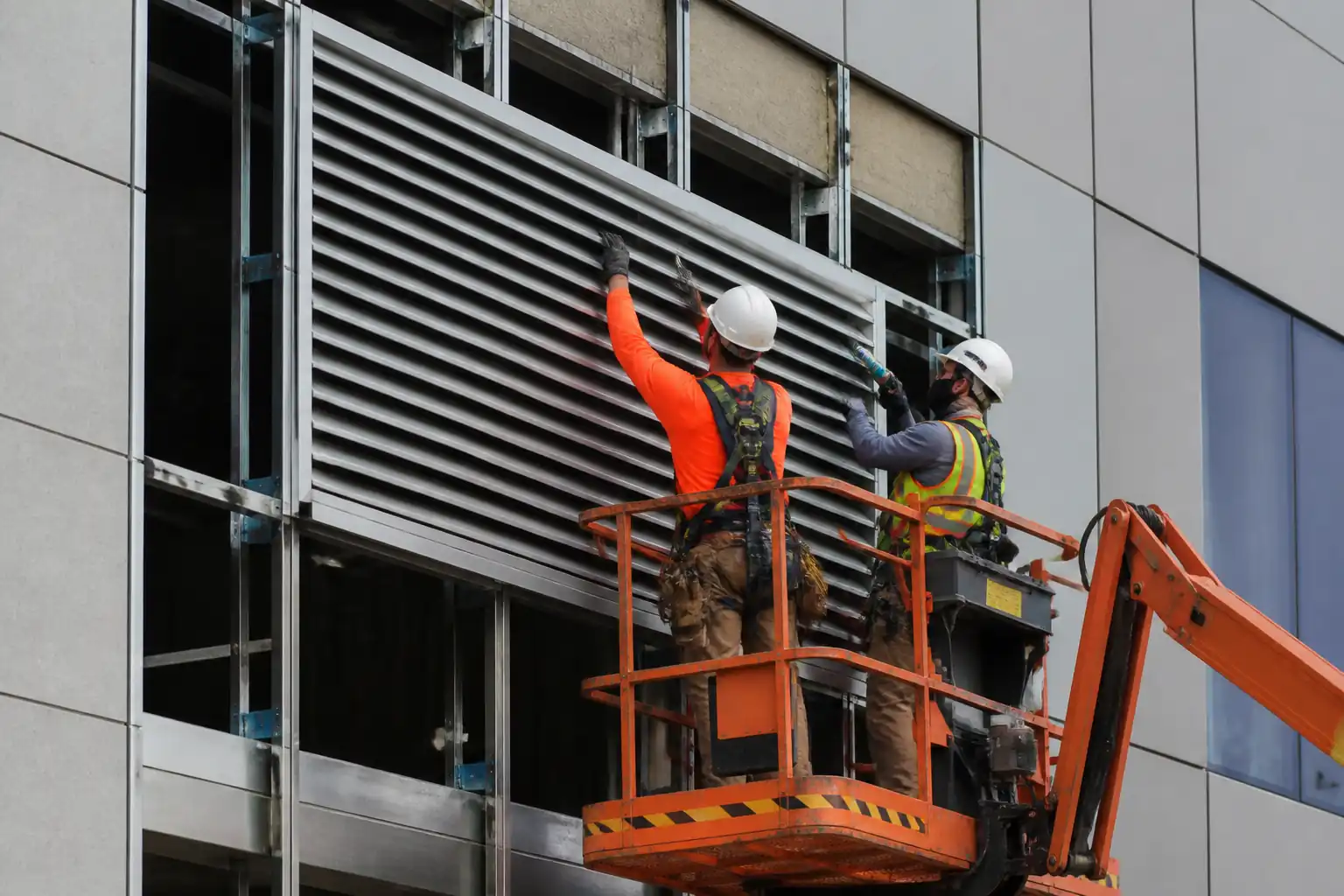

Method Statement: Architectural Louver Installation and Integration with Facade Openings – Method Statement
AI-assisted method statement with matching ITP, PDF download, and Excel export.
More than a static template
Unlike a downloadable Word or PDF template, this method statement is an AI-assisted editable starting point connected directly to a matching Inspection and Test Plan. Every section is structured, project-adaptable, and ready to export.
- AI-assisted drafting — Customize every section with AI for your specific project scope.
- Linked ITP — A matching inspection and test plan is generated alongside the method statement.
- Multiple export formats — Download as a formatted PDF or editable Excel spreadsheet.
- Editable starting point, not a final document — Review, verify, and adjust all content against your project requirements before use.
Static template vs. Quollnet workflow
| Feature | Static template | Quollnet |
|---|---|---|
| Project-specific content | Manual fill-in required | AI-assisted customization |
| Linked ITP | Separate document, no link | Matching ITP included |
| Export formats | Usually PDF only | PDF and Excel |
| Structured sections | Free-form layout | 13 standardized sections |
| Saved to your account | Local file only | Cloud-saved, reusable |
| Content accuracy | You verify everything | AI-assisted, you still verify |
| Cost | Often free but time-intensive | Free to customize and download |
What you can customize
When you save this method statement to your account, every section becomes editable. The following 13 sections are included:
- Scope — Defines the activity and its boundaries.
- References — Standards, specifications, and drawings.
- Responsibilities — Roles and accountabilities.
- Resources — Labour, plant, and equipment summary.
- Materials — Materials and compliance requirements.
- Equipment — Tools and equipment details.
- Prerequisites — Hold points and pre-conditions.
- Method sequence — Step-by-step construction sequence.
- Safety controls — HSE risk controls and PPE.
- Environmental controls — Environmental mitigation measures.
- QA/QC — Quality inspection and test requirements.
- ITP — Inspection and Test Plan table (has its own page).
- Attachments — Referenced drawings and documentation.
Why this method statement is used
This method statement is used to define and communicate the approved procedure for carrying out method statement: architectural louver installation and integration with facade openings on site. It ensures the work is planned in advance, the correct resources and controls are in place, and all personnel understand responsibilities, sequence, quality requirements, and safety controls before work begins. It aligns site execution with the documented scope and acceptance expectations.
Who uses this method statement
This method statement is used by contractors, site supervisors, project engineers, QA/QC engineers, HSE officers, consultants, and client representatives. It serves as a shared reference for planning, execution, supervision, inspection, and approval of the activity on site.
When it is prepared and submitted
The method statement is prepared before the work activity starts and submitted as part of the pre-construction documentation package for review and approval.
Who reviews or approves it
The method statement is usually submitted to the client representative, consultant, resident engineer, or project management consultant for review and approval before the work commences.
Important approval note
This method statement is an AI-assisted editable starting point, not a pre-approved document. Before use on any project, all content must be reviewed and approved by the relevant parties (superintendent, principal contractor, or client representative) in accordance with your contract and project quality plan.
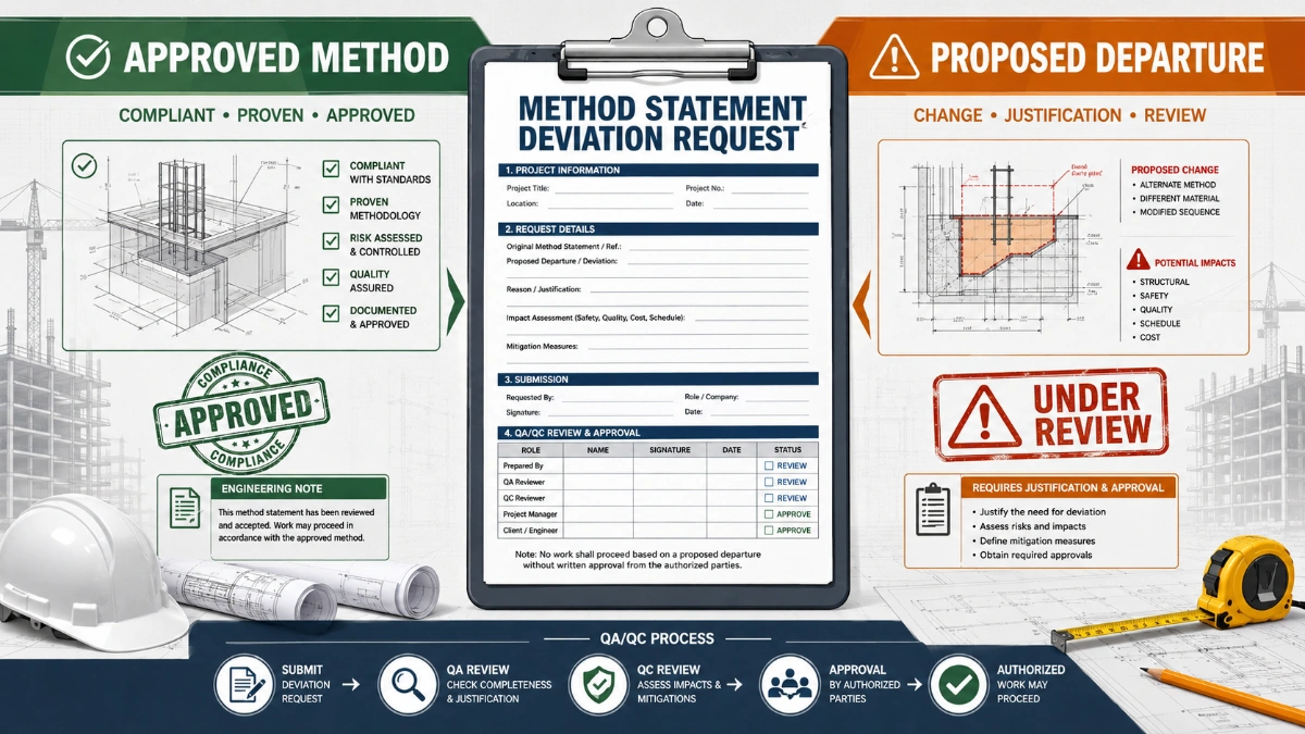
For example: if your specification requires a departure from a referenced standard, that departure must be documented and approved separately — this method statement will not capture that automatically. Always verify against your applicable drawings, specifications, and regulatory requirements.
Method statement content
Document Control
Document Information
- Project Name:
- Method Title: Architectural Louver Installation and Integration with Facade Openings
- Method Date: 2026-08-14
- Document No.: MS-ARC-LVR-001 [Placeholder]
- Revision: R0
- Submitted By:
- Submitted To:
- Prepared By: Principal Civil Engineer [Name]
- Reviewed By: QA/QC Manager [Name]
- Approved By: Project Manager [Name]
Distribution
- Main Contractor, Façade Subcontractor, Consultant, HSE, QA/QC, Stores
Related Documents
- Approved Shop Drawings, ITP, Risk Assessment/Method Statement (RAMS), Manufacturer Installation Manuals, Permits to Work, Lifting Plan, Access Plan, Project Specifications.
Scope
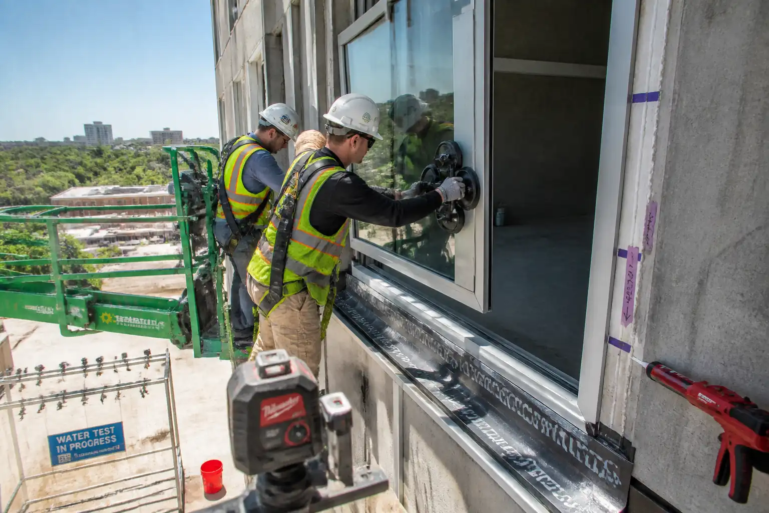
This method statement covers the contract-level procedures for the installation of architectural louvers, including:
- Verification of structural support framing/substrates and anchor interfaces.
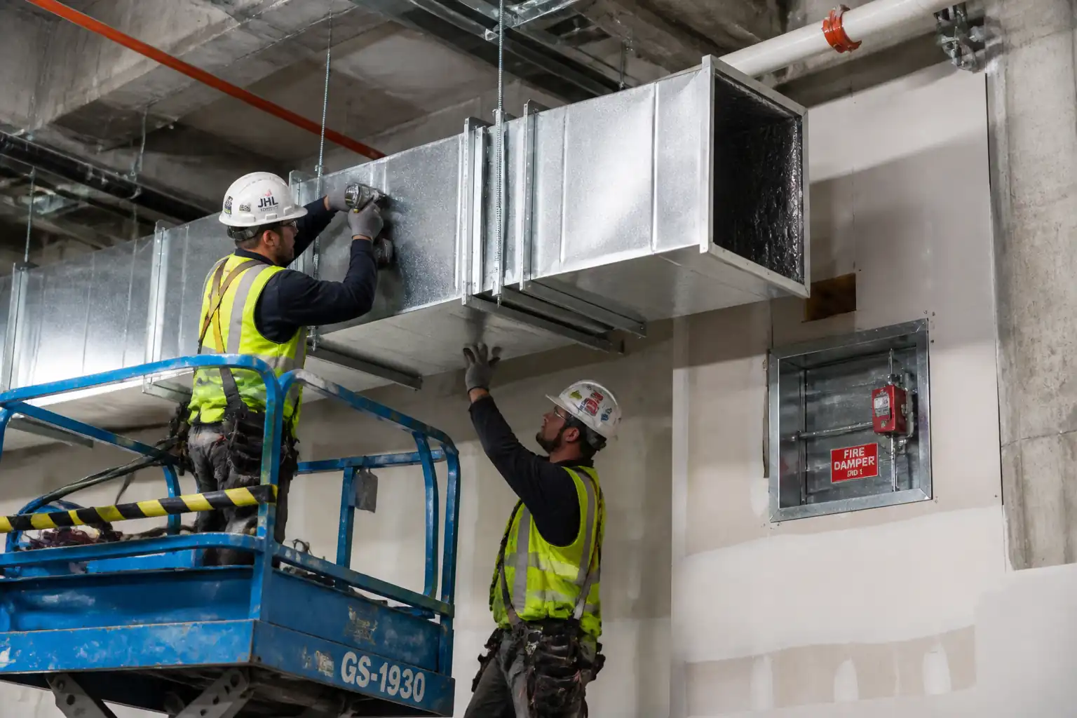
- Setting out, delivery, handling, and storage of louver assemblies and accessories.
- Installation of frames and blades/panels, shimming, fixing, and torqueing.
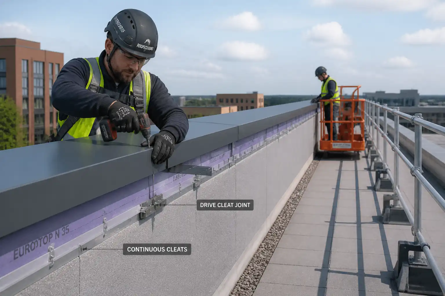
- Weather sealing and integration with facade openings, flashings, and barriers.
- Corrosion protection touch-ups and coating verification.
- Alignment, dimensional checks, and functional drainage/airflow provisions.
- QA/QC inspections, testing, documentation, and handover.
- HSE controls and environmental management.
Exclusions: Permanent structural alterations to primary structure (unless noted), electrical/M&E works (motorized dampers or sensors, if any, by others) [Coordinate].
References
| Document Type | Reference / Number | Revision | Notes |
|---|---|---|---|
| Standard | AMCA 500-L | For air/water penetration, pressure drop ratings. | |
| Standard | ASTM E283/E331/E330 | Project may specify field hose test per AAMA 501.2. | |
| Standard | ACI 318, ACI 355.2, ACI 355.4 | Use ETA/ICC-ES approved anchors where required. | |
| Standard | ASTM C920, ASTM C1193, ISO 11600 | ||
| Standard | AAMA 2604/2605, ISO 12944, ISO 1461, ISO 8501-1 | Touch-up repair per ASTM A780 for galvanizing. | |
| Standard | ISO 19840 / SSPC-PA 2 | ||
| Standard | BS EN 1090 | [Verify per project specifications] | |
| Standard | AAMA 501.2 | Apply to representative areas when specified. | |
| Contract | Project Specs/Drawings | [Verify per project] |
Responsibilities
| Role | Responsibility | Name / Party |
|---|---|---|
| Project Manager | Project Manager | Main Contractor |
| Site/Facade Engineer | Site/Facade Engineer | Subcontractor |
| Façade Supervisor | Façade Supervisor | Subcontractor |
| QA/QC Inspector | QA/QC Inspector | Main/Subcontractor |
| HSE Officer | HSE Officer | Main Contractor |
| Surveyor | Surveyor | Main Contractor |
| MEWP Operator / Rigger | MEWP/Crane Operator & Rigger | Subcontractor |
| Sealant Applicator | Sealant Applicator | Specialist |
| Storekeeper | Storekeeper | Main/Subcontractor |
Resources
| Resource Type | Description | Quantity | Remarks |
|---|---|---|---|
| Labor | Skilled louver installers | 6–12 [Verify per workfront] | |
| Labor | Certified per manufacturer | 2–3 | |
| Staff | QC Inspector, Surveyor | 1 QC + 1 Surveyor | |
| Labor | Certified IPAF/rigging | 2–4 |
Materials
| Material | Specification / Grade | Quantity | Remarks |
|---|---|---|---|
| Louver frames & blades | Finish thickness typically 60–80 µm for powder coat [Verify] | As per BOQ [Verify] | |
| Screws/bolts/rivets | Torque per manufacturer [Verify] | As required | |
| Wedge/adhesive anchors | Design per ACI 318/355 [Verify] | As per design [Verify] | |
| Sealant system | ASTM C920, ISO 11600 (Class 25/50) [Verify] | As required | |
| Shims | Compressive strength adequate for loads [Verify] | As required | |
| Perimeter flashings | Slope outward ≥ 1:12 [Verify] | As required | |
| Coating repair kit | DFT 60–100 µm [Verify] | As required |
Equipment
| Equipment | Capacity / Type | Quantity | Inspection Required |
|---|---|---|---|
| MEWP | Working height per location | As required | |
| Lifting gear | SWL per plan | As required | |
| Drills | 2–4 | ||
| Survey tools | Sets as required | ||
| Torque tools | Range per fasteners | As required | |
| QA/QC test equipment | 1 set |
Prerequisites
Approvals and Documentation
- Approved shop drawings, structural calculations for anchors/sub-framing, and manufacturer installation manuals.
- Approved RAMS and ITP; task-specific risk assessment and lifting plan.
- Material approvals: coating/finish data (AAMA 2604/2605), sealant data (ASTM C920), anchor ETA/ICC-ES.
Site Readiness
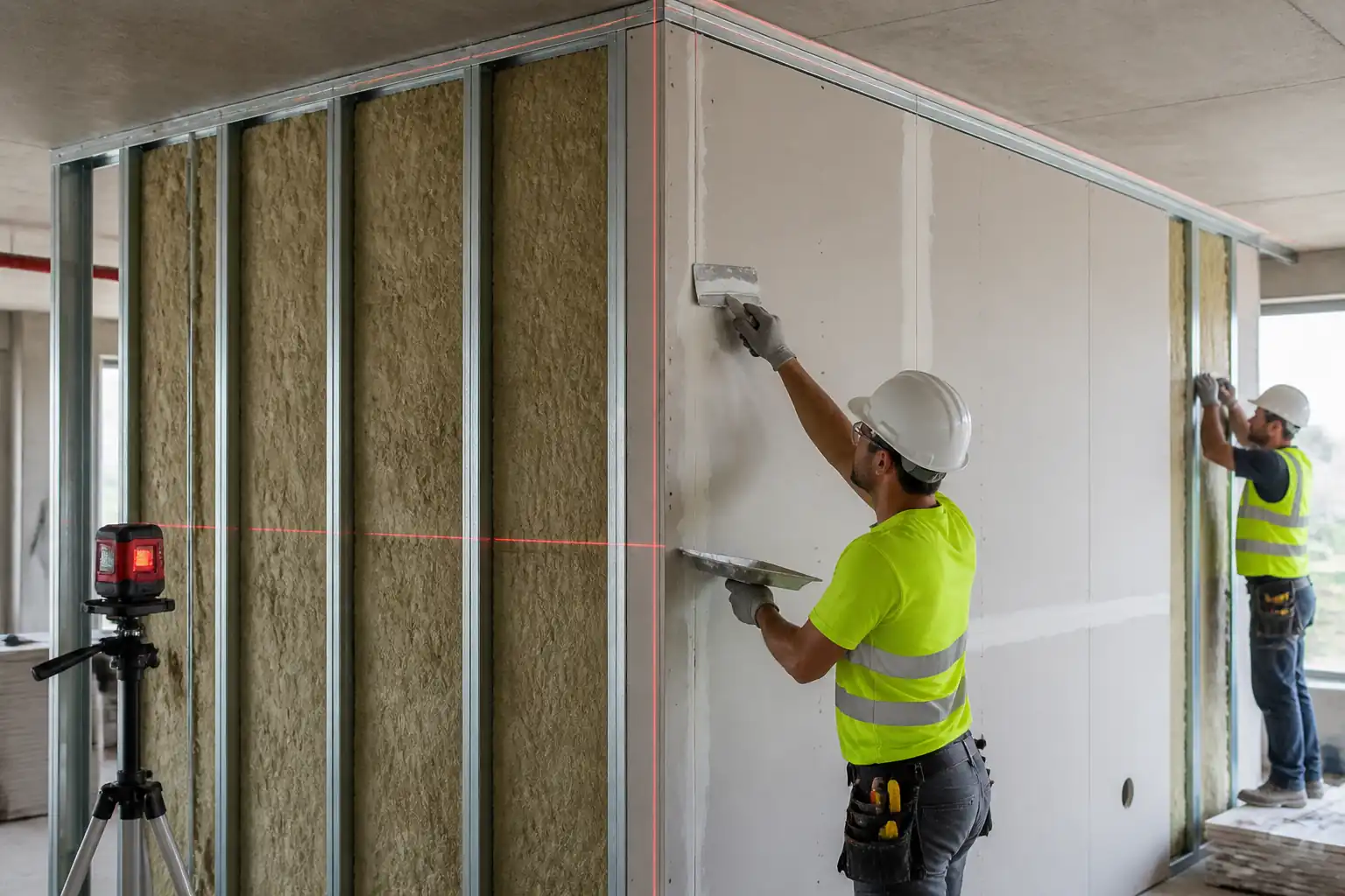
- Surveyed and set-out control points transferred to openings; verify opening sizes, plumb, level, and squareness.
- Substrate strength confirmation for anchors (concrete/masonry/steel) [Verify per design].
- Access and edge protection installed; exclusion zones demarcated.
- Permits to work: work-at-height, hot works (if any cutting/grinding), lifting permit [Verify per project HSE plan and local regulations].
Environmental/Weather
- Work not to proceed during sustained winds > 10 m/s or driving rain impacting sealant application [Verify per manufacturer].
- Confirm compatible temperatures for sealant (typically +5°C to +40°C) and dry substrates.
Utilities/Interfaces
- Confirm MEP clearances behind openings; verify any penetrations or sleeves.
- Confirm compatibility and tie-in details with air/water barriers, flashings, and adjacent cladding.
Mock-up/Training
- Construct and approve representative mock-up including sealing details (where specified).
- Toolbox talk and installer briefing on tolerances, torque settings, and sealant workmanship.
Method Sequence
| Step | Activity | Description | Responsibility | Inspection / Hold Point |
|---|---|---|---|---|
| 1 | Material receipt and storage | Inspect deliveries for damage, finish defects, correct sizes; store on padded racks, off the ground, protected from moisture and UV. | Storekeeper / QC | Visual check; finish check |
| 2 | Setting out | Transfer control lines; mark louver frame perimeter and fixing points. | Surveyor / Site Engineer | Survey check |
| 3 | Substrate/support verification | Check support framing/substrate for levelness, plumbness, integrity; verify embedments/edge distances. | Site Engineer / QC | Hold point prior to fixing |
| 4 | Install flashings/sill pans | Fit end-dammed sill pans and flashings with outward slope; seal laps. | Façade Supervisor | Visual |
| 5 | Anchor hole drilling | Drill holes per layout using dust extraction; clean holes by brush-blow-vac cycle. | Installers / QC | Spot checks |
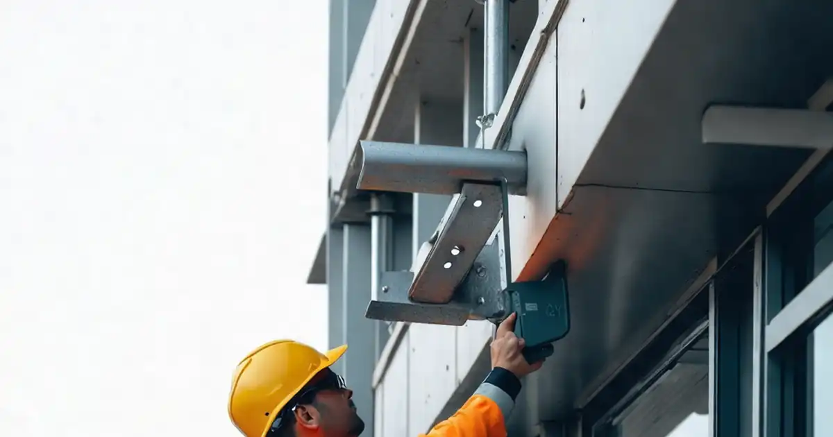
| 6 | Anchor installation | Install mechanical/adhesive anchors per manufacturer (adhesive anchors by certified installers). Respect gel/cure times. | Installers / QC | Witness point |
| 7 | Anchor proof testing | Perform proof load tests on sample anchors per project testing plan. | QC / Third-party | Hold point before proceeding |
| 8 | Install sub-framing/angles | Fix sub-framing; introduce non-corroding shims to achieve line/level; isolate dissimilar metals. | Façade Supervisor / Installers | Dimensional check |
| 9 | Dry fit louver frame | Trial position frame; verify clearances and squareness before final fixation. | Installers / QC | Visual |
| 10 | Final fix louver frame | Secure frame to sub-framing with specified fasteners; apply torque. | Installers | Witness torque |
| 11 | Install blades/panels | Install louver blades or modules per sequence; ensure correct orientation (drainage direction). | Installers | Visual |
| 12 | Perimeter sealing | Prepare joints (clean, dry); insert backer rod; apply sealant; tool within open time. | Sealant Applicator / QC | Witness bead formation |
| 13 | Sealant adhesion test | Field adhesion test per ASTM C1193 on representative joints. | QC / Sealant Applicator | Witness point |
| 14 | Corrosion protection touch-up | Treat cut edges and damage with zinc-rich primer; verify DFT. | Installers / QC | DFT check |
| 15 | Interface integration | Tie-in to air/water barrier and adjacent cladding per details; install seal tapes/flashings. | Façade Supervisor / Site Engineer | Hold point prior to concealment |
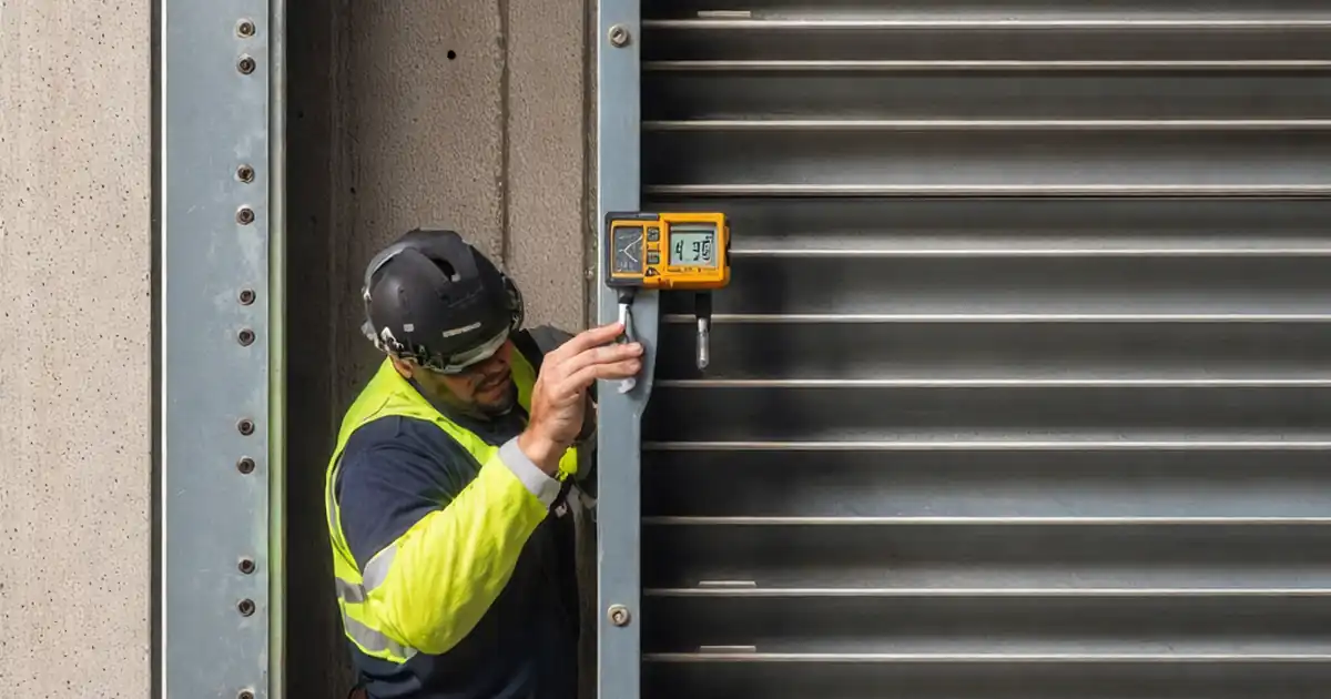
| 16 | Alignment and dimensional check | Verify level, plumb, squareness, and spacing between adjacent units. | QC / Surveyor | Dimensional survey |
| 17 | Water leakage field check (if specified) | Conduct hose test to AAMA 501.2 on representative areas with witness. | QC / Consultant | Witness point |
| 18 | Cleaning and protection | Remove debris, clean finishes with non-abrasive cleaners; install temporary protection if further works ongoing. | Installers | Visual |
| 19 | Final inspection and handover | Comprehensive visual and dimensional acceptance with client/consultant. | PM / QC / Consultant | Hold point |
Health, Safety and Environment (HSE) – Task-Specific Controls
Key Hazards and Controls
1) Working at height (MEWPs/scaffolds)
- Consequence: Fall leading to serious injury or fatality.
- Engineering/Procedural Controls: Certified MEWPs with guardrails; full body harness with lanyard to approved anchor if required by manufacturer; pre-use inspection; maintain exclusion zone; competent operator; do not exceed wind limits.
- PPE: Helmet with chin strap, full body harness, lanyard, non-slip safety boots, gloves, safety glasses.
- Collective Measures: Edge protection, toe boards, traffic marshals.
- Inspection/Permit/Supervision: Daily MEWP inspection, valid LOLER/3rd-party certificates; Work-at-Height PTW; HSE supervision. [Verify per project HSE plan and local regulations]
2) Manual handling of louver panels
- Consequence: Strains, crush injuries, dropped loads.
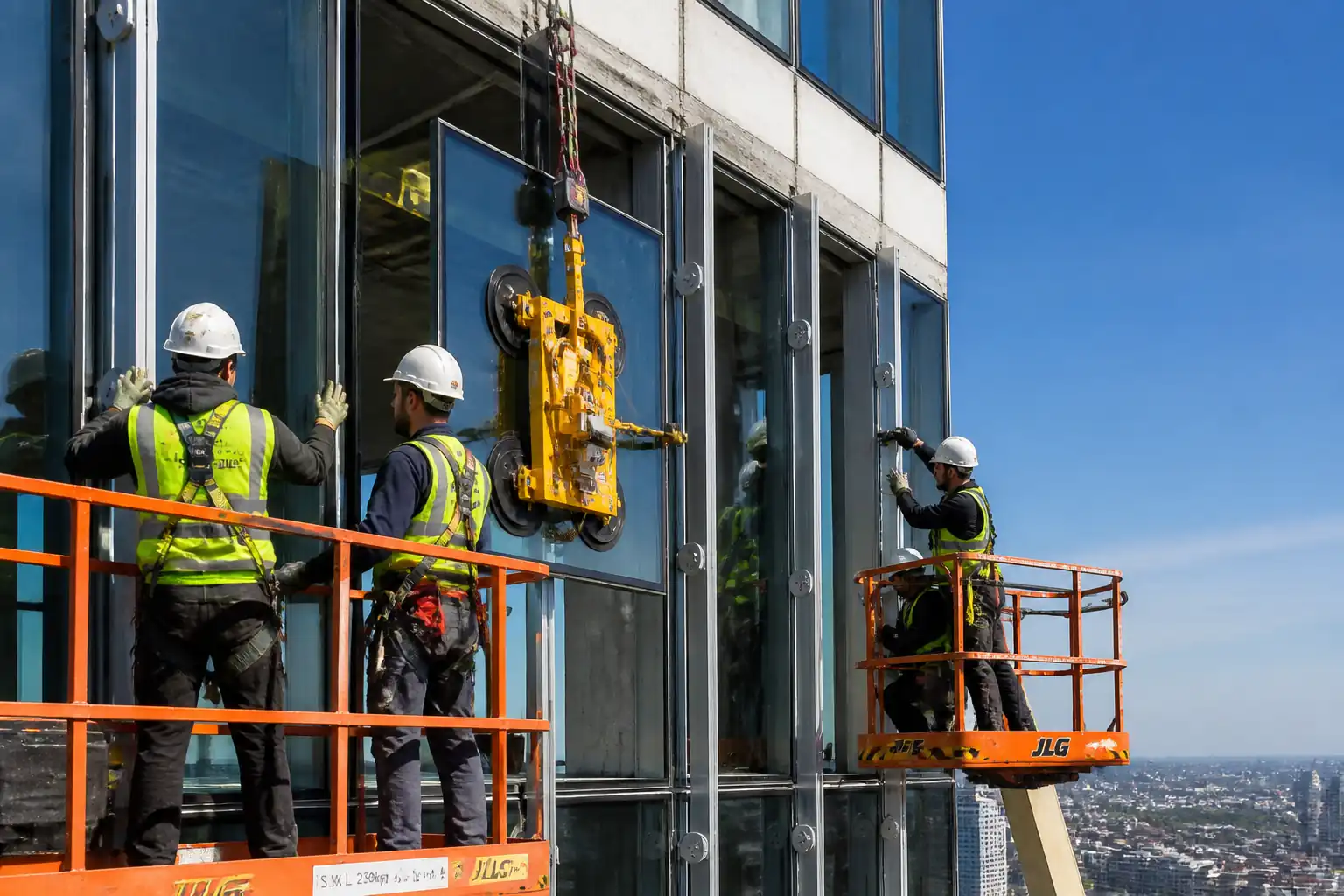
- Controls: Use team lifts and suction pads; use tag lines; plan lifts per lifting plan; store panels vertically with padding; limit panel weight per team capability.
- PPE: Cut-resistant gloves, safety footwear, eye protection.
- Collective Measures: Mechanical aids (trolleys), designated laydown areas.
- Inspection/Permit/Supervision: Lifting plan review; toolbox talk; spotter present.
3) Drilling and anchoring in concrete/masonry
- Consequence: Silica dust inhalation, eye injury, anchor failure.
- Controls: On-tool dust extraction; vacuum and wet suppression where feasible; hole cleaning protocol; follow ACI 355.2/355.4; only trained installers for adhesive anchors; curing times enforced.
- PPE: Safety glasses/face shield, FFP2/FFP3 respirator, hearing protection, gloves.
- Collective Measures: Local extraction, barriers to segregate work area.
- Inspection/Permit/Supervision: Hot works permit if grinding; monitor anchor logs; QC witness on sample anchors.
4) Use of chemicals (sealants/adhesives)
- Consequence: Dermal/respiratory irritation, fire risk (solvents).
- Controls: Review MSDS; ensure ventilation; use compatible cleaners/primers; avoid mixing incompatible materials; maintain spill kits.
- PPE: Nitrile gloves, safety glasses, long sleeves; respirator if required by MSDS.
- Collective Measures: Chemical storage cabinet, drip trays.
- Inspection/Permit/Supervision: COSHH assessment; MSDS on site; HSE inspections.
5) Interface works at façade openings
- Consequence: Falls through openings, dropped objects to areas below.
- Controls: Temporary edge protection; tool lanyards; debris nets; exclusion zone below; sequencing to avoid working beneath.
- PPE: Helmet with chin strap, gloves, safety boots, eye protection.
- Collective Measures: Barricades, signage, spotters.
- Inspection/Permit/Supervision: Work-at-height PTW; daily inspections; supervisor oversight.
6) Power tools and torqueing
- Consequence: Hand-arm vibration, flying debris, pinch points.
- Controls: Use calibrated torque wrenches; set torque on low speed; use guards; rotate tasks to control HAVS exposure.
- PPE: Eye protection, gloves, hearing protection.
- Collective Measures: PAT testing; maintenance logs.
- Inspection/Permit/Supervision: Pre-use checks; tool box talk; supervision.
7) Noise and vibration
- Consequence: Hearing damage, nuisance to neighbors.
- Controls: Time restrictions; damped drills; maintain bits sharp.
- PPE: Ear defenders/plugs.
- Collective Measures: Acoustic screens if needed.
- Inspection/Permit/Supervision: Noise monitoring if required; HSE oversight.
8) Weather exposure and wind
- Consequence: Loss of control of panels/MEWP instability.
- Controls: Suspend lifts above wind threshold; secure loose items; monitor forecasts.
- PPE: Weather-appropriate clothing, non-slip footwear.
- Collective Measures: Weather policy.
- Inspection/Permit/Supervision: Supervisor go/no-go decision; record in daily permits.
Note: Where local regulations or the project HSE plan impose stricter controls, comply accordingly. [Verify per project HSE plan and local regulations]
Environmental Controls
Controls
- VOC and solvent management: Select low-VOC sealants where possible; keep containers closed; avoid spillage; provide drip trays.
- Waste segregation: Separate metal offcuts, plastic packaging, sealant tubes (hazardous if uncured), and general waste; dispose via licensed contractor.
- Dust control: Use on-tool extraction; HEPA vacuums; damp down if needed; prevent dust migration to occupied areas.
- Noise: Schedule noisy works in permitted hours; use quieter equipment and maintain tooling.
- Stormwater protection: Prevent washout and debris entering drains; use drain covers and filter socks near workface.
- Surface protection: Mask adjacent finishes prior to sealing/painting; avoid overspray; immediate cleanup using approved cleaners.
- Wildlife and façade intakes: If near live air intakes, coordinate temporary closures; avoid trapping debris within ventilation paths.
- Material sustainability: Preserve protective films until final cleaning (not exceeding manufacturer window) to reduce rework and waste [Verify].
Quality Assurance and Quality Control
General
- All works to comply with approved shop drawings, specifications, and referenced standards. Deviations require NCR and engineer approval.
Inspection & Testing Regime (Typical)
- Receiving inspection: 100% of deliveries; finish and documentation check.
- Substrate/support verification: 100% before installation (Hold Point).
- Anchors: Installation logs 100%; proof load tests 5% per type/elevation, min 3 per area [Verify per project].
- Torque verification: 10% of mechanical fasteners per unit, min 3 points [Verify].
- Alignment/Dimensions: 100% per unit.
- Sealant field adhesion: First 3 joints per batch/day, then 1 per 50 m or per 25 units [Verify].
- Coating DFT (touch-up/repair): 1 reading per repaired spot; min 3 per unit with repairs [Verify].
- Water leakage field check (AAMA 501.2): Representative areas per spec (e.g., 1 per elevation) [Verify].
Acceptance Criteria (Typical)
- Plumb/Level: ≤2 mm/m, not exceeding 5 mm overall per unit [Verify].
- Squareness: Diagonals within 3 mm for ≤2 m frames; larger frames ≤L/1000 [Verify].
- Gaps/Joints: Uniform within ±2 mm; no open joints; sealant bead continuous and properly tooled.
- Fasteners: Correct grade/length; torque within manufacturer limits; no stripped heads.
- Anchors: Embedment/edge distance per design; proof load passes with no slip/failure.
- Coatings: No pinholes/runs; repair DFT 60–100 µm; powder coat thickness 60–80 µm unless specified otherwise [Verify].
- Water check: No leakage beyond the plane intended to remain dry (interior or cavity boundary) [Verify].
Records
- ITP/IRs, checklists, torque and anchor logs, adhesion and water test reports, DFT logs, NCR/CAR (if any), as-built drawings, O&M manuals, warranties.
Attachments
- Louver Installation Checklist (pre/during/post)
- Anchor Installation & Proof Test Log (template)
- Torque Verification Log (template)
- Sealant Application Log and Field Adhesion Test Form
- DFT Measurement Log for Touch-up Areas
- Approved Shop Drawings and Details (interfaces, flashings, anchors)
- Manufacturer Data Sheets: Louvers, Fasteners, Anchors, Sealants, Coatings (MSDS included)
- Calibration Certificates: Torque wrenches, pull-test equipment, DFT gauges
- Lifting Plan and Equipment Certificates
- Work-at-Height Permit and Daily MEWP Inspection Forms
- Risk Assessment / Method Statement (RAMS)
- Non-Conformance Report (NCR) / Corrective Action Report (CAR) forms
- O&M Manual and Warranty Certificates (upon completion)
This content is a read-only public reference. Download or customize to get an editable version.
ITP preview
The first inspection activities from the linked ITP for Method Statement: Architectural Louver Installation and Integration with Facade Openings:
| Activity | Inspection / Test | Acceptance Criteria | Responsibility | Record |
|---|---|---|---|---|
| Pre-install submittals | Review approvals: drawings, RAMS, ITP, product data | All submittals approved; revisions current | Contractor QA/QC / Consultant | Approved submittals |
| Material receiving inspection | Check quantities, finish, certifications | Compliant with PO/spec; no damage/defects | Contractor QA/QC | Delivery inspection report |
| Substrate/support verification | Plumb, level, flatness, edge distance | Within specified tolerances; structurally sound | Contractor QA/QC / Consultant | IR with measurements |
Showing 3 of 12 inspection activities. View full ITP →
Related Inspection and Test Plan
An Inspection and Test Plan (ITP) is available for Method Statement: Architectural Louver Installation and Integration with Facade Openings. The ITP defines the inspection activities, acceptance criteria, hold and witness points, responsible parties, and records required to verify the work described in this method statement.
View the Method Statement: Architectural Louver Installation and Integration with Facade Openings ITP →Frequently asked questions
Continue with related Quollnet resources connected to this method statement.