Method Statement: Gypsum Board Partition Installation – Method Statement
AI-assisted method statement with matching ITP, PDF download, and Excel export.
More than a static template
Unlike a downloadable Word or PDF template, this method statement is an AI-assisted editable starting point connected directly to a matching Inspection and Test Plan. Every section is structured, project-adaptable, and ready to export.
- AI-assisted drafting — Customize every section with AI for your specific project scope.
- Linked ITP — A matching inspection and test plan is generated alongside the method statement.
- Multiple export formats — Download as a formatted PDF or editable Excel spreadsheet.
- Editable starting point, not a final document — Review, verify, and adjust all content against your project requirements before use.
Static template vs. Quollnet workflow
| Feature | Static template | Quollnet |
|---|---|---|
| Project-specific content | Manual fill-in required | AI-assisted customization |
| Linked ITP | Separate document, no link | Matching ITP included |
| Export formats | Usually PDF only | PDF and Excel |
| Structured sections | Free-form layout | 13 standardized sections |
| Saved to your account | Local file only | Cloud-saved, reusable |
| Content accuracy | You verify everything | AI-assisted, you still verify |
| Cost | Often free but time-intensive | Free to customize and download |
What you can customize
When you save this method statement to your account, every section becomes editable. The following 13 sections are included:
- Scope — Defines the activity and its boundaries.
- References — Standards, specifications, and drawings.
- Responsibilities — Roles and accountabilities.
- Resources — Labour, plant, and equipment summary.
- Materials — Materials and compliance requirements.
- Equipment — Tools and equipment details.
- Prerequisites — Hold points and pre-conditions.
- Method sequence — Step-by-step construction sequence.
- Safety controls — HSE risk controls and PPE.
- Environmental controls — Environmental mitigation measures.
- QA/QC — Quality inspection and test requirements.
- ITP — Inspection and Test Plan table (has its own page).
- Attachments — Referenced drawings and documentation.
Why this method statement is used
This method statement is used to define and communicate the approved procedure for carrying out method statement: gypsum board partition installation on site. It ensures the work is planned in advance, the correct resources and controls are in place, and all personnel understand responsibilities, sequence, quality requirements, and safety controls before work begins. It aligns site execution with the documented scope and acceptance expectations.
Who uses this method statement
This method statement is used by contractors, site supervisors, project engineers, QA/QC engineers, HSE officers, consultants, and client representatives. It serves as a shared reference for planning, execution, supervision, inspection, and approval of the activity on site.
When it is prepared and submitted
The method statement is prepared before the work activity starts and submitted as part of the pre-construction documentation package for review and approval.
Who reviews or approves it
The method statement is usually submitted to the client representative, consultant, resident engineer, or project management consultant for review and approval before the work commences.
Important approval note
This method statement is an AI-assisted editable starting point, not a pre-approved document. Before use on any project, all content must be reviewed and approved by the relevant parties (superintendent, principal contractor, or client representative) in accordance with your contract and project quality plan.
For example: if your specification requires a departure from a referenced standard, that departure must be documented and approved separately — this method statement will not capture that automatically. Always verify against your applicable drawings, specifications, and regulatory requirements.
Method statement content
Scope
Description
This method covers the supply, installation, and finishing of internal gypsum board partitions including:
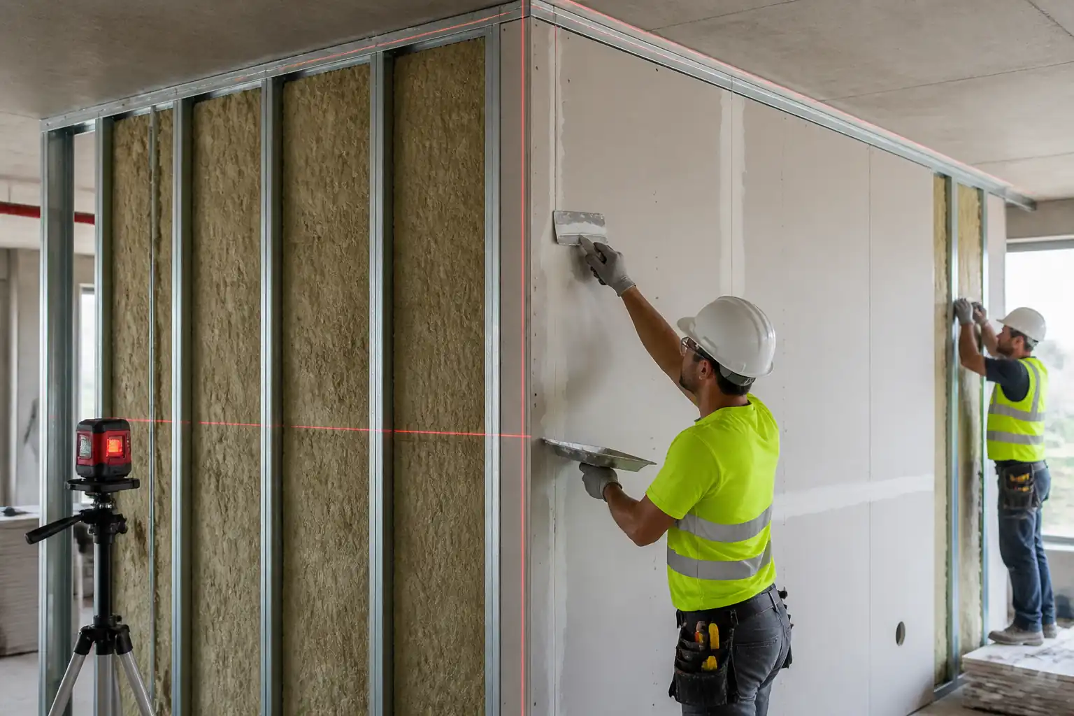
- Setting out, fixing floor/ceiling tracks, studs, and deflection head details.
- Installation of single/double layer gypsum boards, moisture-resistant (MR) and fire-resistant (FR) boards as specified.
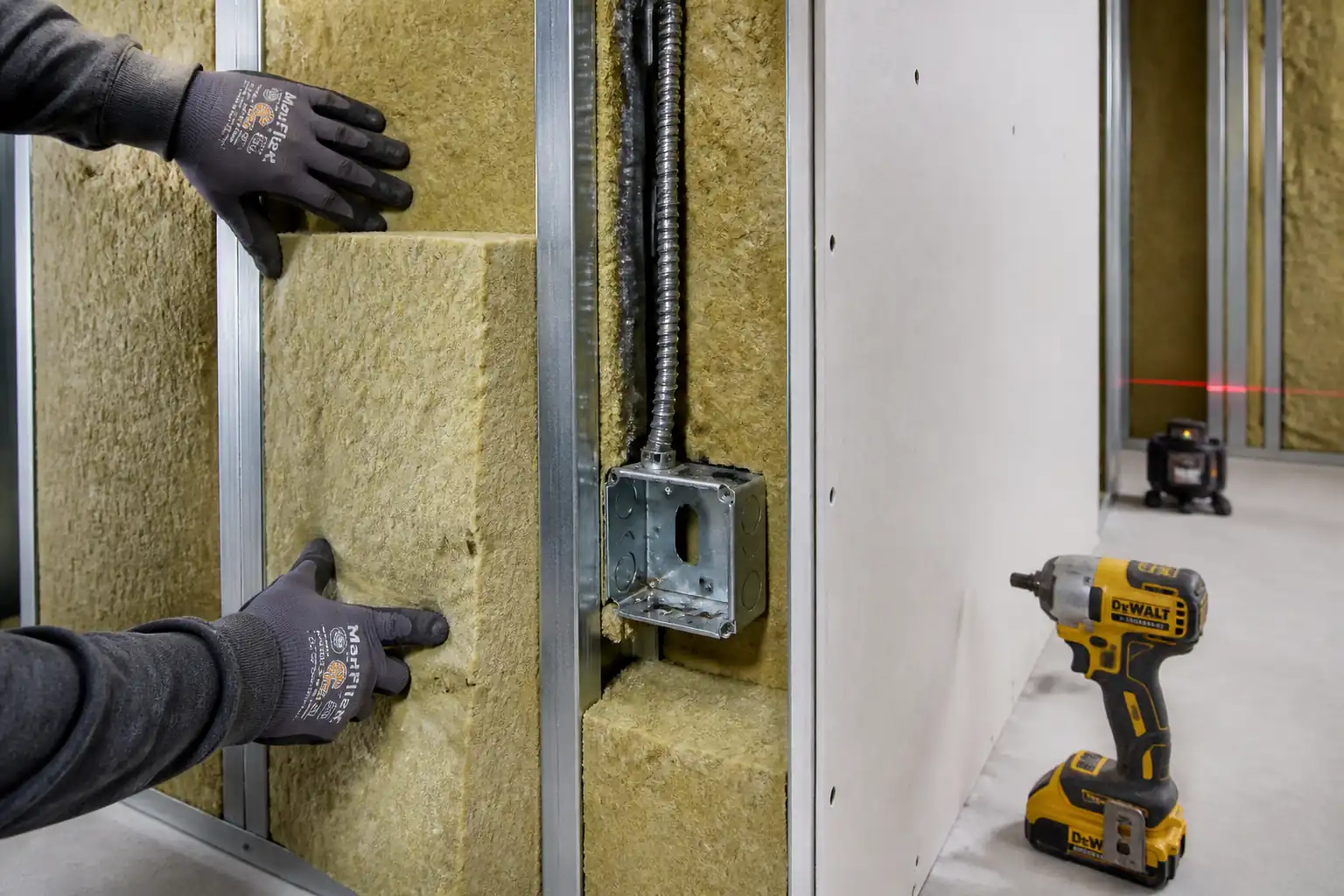
- Service coordination and framing for openings, penetrations, and recessed boxes.
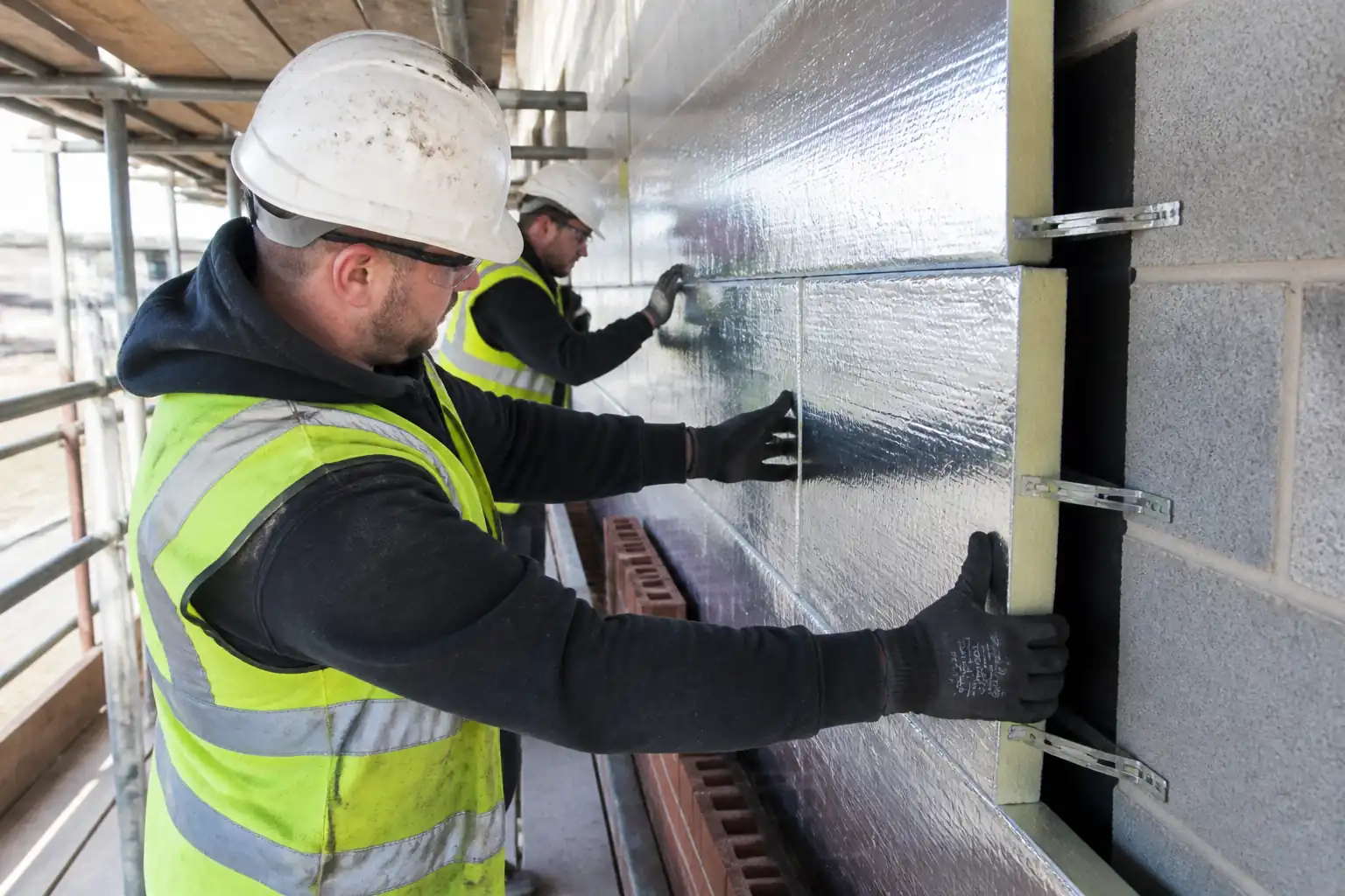
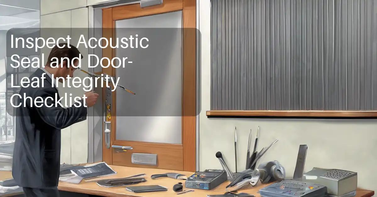
- Placement of acoustic/mineral wool insulation, perimeter seals, and putty pads.
- Joint treatment, corner beads, and finishing to specified level prior to painting.
- Quality control inspections, hold and witness points, and documentation.
Exclusions
- Structural framing beyond light-gauge partition system.
- Final painting and decorative finishes (by others).
- Above-ceiling firestopping not forming part of partition head-of-wall system unless detailed.
Location
- As indicated on architectural/partition layout drawings [Verify per project drawings].
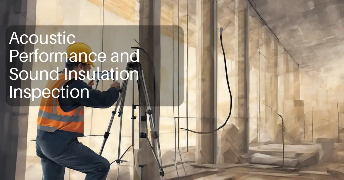
Performance Requirements
- Fire resistance rating: As per UL/BS EN tested assemblies or project details [Verify per project specifications].
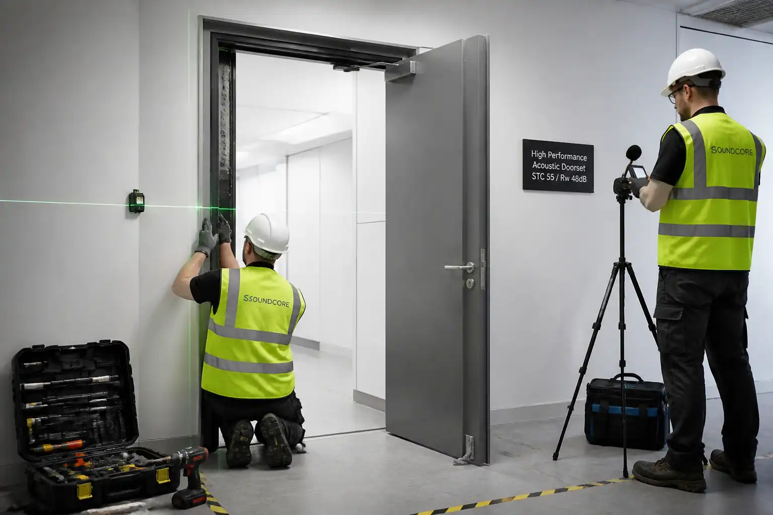
- Acoustic rating (STC/Rw): Target STC 45–55 typical for office partitions; confirm exact requirement [Verify per project specifications].
- Moisture exposure: MR boards in wet areas per drawings [Verify].
- Seismic/deflection head: Allow for building movement as detailed [Verify].
References
| Document Type | Reference / Number | Revision | Notes |
|---|---|---|---|
| Standard | ASTM C840 | ||
| Standard | ASTM C754 | ||
| Standard | ASTM C645 / C1002 / C475 | ||
| Guideline | GA-216 / GA-214 / GA-600 | ||
| Standard | BS EN 520 / BS EN 14195 / EN 13501-2 | ||
| Standard | ISO 16283 / ISO 10140 | ||
| Project Docs | Verify exact assembly types and ratings. |
Responsibilities
| Role | Responsibility | Name / Party |
|---|---|---|
| Project Manager | Overall compliance with specifications, program, and safety. | Main Contractor |
| Construction Manager / Site Engineer | Daily coordination, permits, method implementation, look-ahead planning. | Main Contractor |
| QA/QC Engineer | Inspections, ITP control, NCR/SI management, documentation. | Main Contractor |
| Drywall Foreman | Crew supervision, workmanship, sequencing, coordination with MEP. | Subcontractor |
| HSE Officer | Task-specific risk assessments, toolbox talks, monitoring of controls and permits. | Main Contractor |
| MEP Coordinator | Coordination of penetrations, back-boxes, and routing within partitions. | Main Contractor |
| Certified Firestop Installer | Approved products and tested systems for fire/acoustic seals. | Specialist |
| Consultant/Employer’s Representative | Witness points/hold points as per ITP; acceptance of completed works. | Engineer |
Resources
| Resource Type | Description | Quantity | Remarks |
|---|---|---|---|
| Labor | 1 crew = 1 Foreman + 4–8 installers [Adjust per productivity] | ||
| Staff | 1 | ||
| Staff | 1 (shared) | ||
| Staff | As required |
Materials
| Material | Specification / Grade | Quantity | Remarks |
|---|---|---|---|
| Gypsum boards Type A, 12.5 mm or 15 mm | BS EN 520 Type A; ASTM C1396; Edge: tapered; Length per site logistics [Verify]. | As per BOQ | |
| Moisture-Resistant (MR) Boards | BS EN 520 Type H1/H2 or ASTM C1396 MR [Verify]. | As per drawings | |
| Fire-Resistant (FR) Boards | BS EN 520 Type F; GA-600/UL Listed assemblies [Verify]. | As required | |
| Galvanized steel studs and tracks | BS EN 14195; ASTM C645; G40/G60 zinc coat; thickness 0.6–1.0 mm [Verify]. | As per layouts | |
| Drywall screws Type S/W | ASTM C1002; lengths 25–41 mm; corrosion resistant where required [Verify]. | Consumable | |
| Jointing compound and tape | ASTM C475; paper/fiberglass tape per GA-214; Low-VOC [Verify]. | Consumable | |
| Corner beads/edge trims | Galvanized/PVC, compatible with system. | As required | |
| Mineral wool insulation batts | 32–48 kg/m³ density; thickness to stud depth; non-combustible (Euroclass A1). [Verify]. | As per wall area | |
| Acoustic sealant | Non-hardening, low-VOC, tested for STC assemblies [Verify]. | Consumable | |
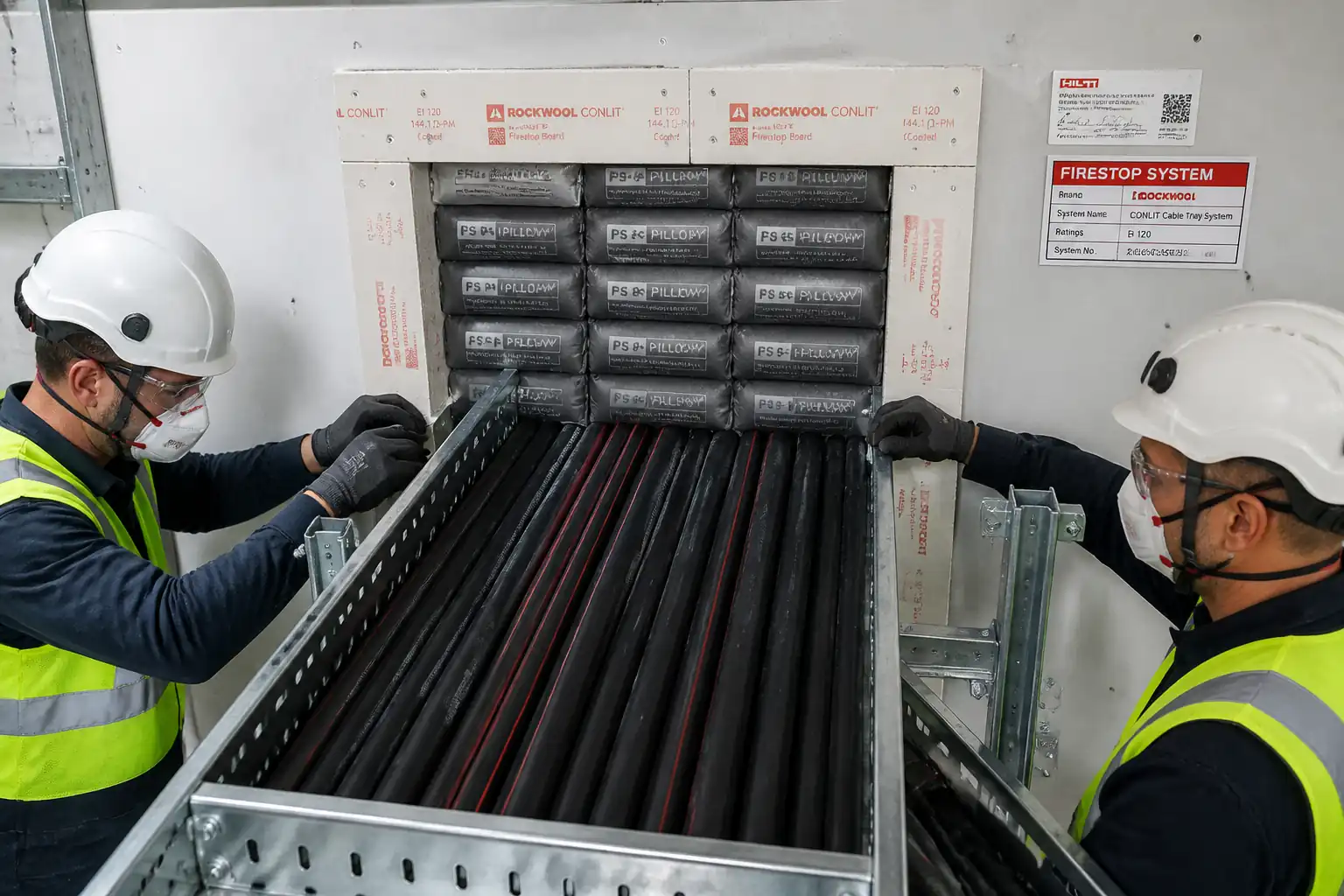
| Firestop sealants, putty pads, collars | UL/ETA listed systems to required FRL [Verify]. | As required | |
| Deflection head track and intumescent/acoustic gasket | Manufacturer’s tested details; movement allowance per design [Verify]. | As required | |
| Anchors/fasteners | Concrete anchors M6–M8 or powder-actuated where permitted; edge distances per manufacturer [Verify]. | As required |
Equipment
| Equipment | Capacity / Type | Quantity | Inspection Required |
|---|---|---|---|
| Rotary hammer drill with integrated M-class vacuum | Ø6–10 mm bits | 2–4 | Daily PAT/inspection [Verify]. |
| Cordless screw guns with depth stop | 18–36V | 2–4 | Daily inspection |
| Laser level and accessories | ±2 mm @ 10 m | 1–2 | Calibration certificate [Verify]. |
| Drywall panel lift/board trolley | Up to 60 kg | 1 | Visual check |
| Mobile scaffold/step ladders/platforms | Work at height up to ceiling | As required | Tagged per scaffold system [Verify]. |
| Stud cutter/crimper/tin snips | Up to 1.0 mm sheet | 1 | Daily inspection |
| Hand tools (T-square, knives, rasps, chalk line, plumb bob) | As required | Good condition |
Prerequisites
Approvals and Documentation
- Approved shop drawings, partition schedules, and fire/acoustic details.
- Material submittals and MSDS, manufacturer installation manuals approved.
- ITP approved and hold/witness points agreed with Consultant.
Site Conditions
- Building envelope substantially sealed; temperature ≥10°C and RH per manufacturer (typically ≤70%) during and after installation [Verify per project specifications].
- Substrates (slab/soffit) ready, surveyed, and marked; floor level variations addressed.
- PT slab/embedded services scanning completed; drilling permit obtained where required [Verify per project HSE plan and local regulations].
Mock-up
- Build and obtain approval of typical wall mock-up showing head-of-wall, door opening, services, joints, and finish level [Verify].
Coordination
- Latest coordinated MEP drawings; final locations of back-boxes, pipes, and openings confirmed.
- Delivery path and storage area dry, flat, and protected from moisture; boards acclimatized min. 24 h.
Tools and Calibrations
- Laser level and torque-limited screw guns calibrated/checked; vacuum extraction available for drilling/cutting.
Method Sequence
| Step | Activity | Description | Responsibility | Inspection / Hold Point |
|---|---|---|---|---|
| 1 | Setting out | Transfer grid/partition lines using laser and chalk. Mark door frames, control joints, services, and deflection head zones. | Site Engineer / Foreman | Check against approved drawings. |
| 2 | Fix floor track | Lay acoustic gasket beneath track. Fix track to slab using anchors at ≤600 mm c/c and ≤100 mm from ends; maintain straightness; avoid PT tendons/embedded services. | Drywall Crew | Permit to drill; substrate scan records. |
| 3 | Install head track/deflection detail | Fix slotted deflection track to soffit/beam as per tested detail. Provide required movement gap (typ. 15–25 mm) and fire/acoustic gasket if specified. | Drywall Crew | Verify tested assembly reference. |
| 4 | Erect studs | Insert studs into tracks; orient open side same direction. Space at 400 or 600 mm c/c as specified. Provide additional studs at openings, abutments, sanitary fixtures, and for services. | Drywall Crew | Spacing and plumb check with level/laser. |
| 5 | Frame door/window openings | Install jamb studs (paired or boxed) and headers per door schedule; fix reinforcing plates/track header; install temporary bracing for squareness. | Drywall Crew | Door frame dimensions and level. |
| 6 | First-side boarding | Install first layer boards vertically unless system requires horizontal. Maintain 10 mm gap above finished floor; perimeter 3–5 mm gap to be sealed. Screw spacing: edges ≤200 mm, field ≤300 mm. Stagger vertical joints ≥400 mm between adjacent studs when multi-layer. | Drywall Crew | Visual and gauge check for screw depth. |
| 7 | Services rough-in and backing | Install conduits, boxes, and pipes within stud cavity. Provide noggings/backing for fixtures. Offset back-to-back boxes ≥300 mm or use acoustic/FR boxes. Protect openings with grommets/edge guards. | MEP Trades with Drywall Support | Coordination check with MEP drawings. |
| 8 | Acoustic insulation placement | Place mineral wool full height, tight to studs without gaps/voids; cut around services snug-fit. | Drywall Crew | Continuity check with flashlight/thermal camera if available. |
| 9 | Perimeter/acoustic/fire seals (first side) | Apply continuous acoustic sealant at floor, head, and abutments. Install firestop materials at head-of-wall and penetrations per listed systems before closure. | Firestop Specialist / Drywall Crew | Check listing numbers and materials. |
| 10 | Second-side boarding | Install boards; stagger joints relative to first side by ≥400 mm; maintain screw spacing and perimeter gaps; maintain deflection gap at head with no fasteners to structural soffit per detail. | Drywall Crew | Visual and gauge check. |
| 11 | Joint treatment and trims | Install corner beads/edge trims. Tape all joints and internal angles. Apply joint compound: embed coat + 2 finish coats for Level 4 (or as specified). Feather edges ≥200 mm overall width on tapered joints. | Drywall Finishers | Cure/dry between coats per data sheet. |
| 12 | Final surface prep and snagging | Light sanding with dust extraction; repair imperfections; clean surfaces; protect until painting. | Drywall Finishers | Joint quality and surface flatness check. |
Health, Safety, and Environment (HSE) – Task-Specific Safety Controls
Key Hazards and Controls
- Hazard: Drilling into slabs/soffits (risk of striking PT tendons/embedded services)
- Likely consequence: Structural damage, electric shock, flooding, injury.
- Engineering/procedural control: Mandatory scanning of slab/soffit; use marked safe zones; drilling permit with signed scan plan; stop work if unexpected resistance.
- Required PPE: Safety glasses, cut-resistant gloves, hearing protection, dust mask (P2/P3).
- Collective preventive measure: Use drill with depth stop and M-class vacuum extraction; cordon area below for overhead works.
-
Inspection/permit/supervision: Permit-to-drill; HSE oversight; daily tool inspection. [Verify per project HSE plan and local regulations]
-
Hazard: Manual handling of boards (large, awkward loads)
- Likely consequence: Strains, crush injuries, cuts.
- Engineering/procedural control: Team lifts or panel lifter; limit carry distances; store boards flat near workface; use gloves with grip.
- PPE: Cut-resistant gloves, safety footwear, long sleeves.
- Collective measure: Mechanical aids (trolleys/lifts); clear access routes.
-
Inspection/permit/supervision: Manual handling training; supervision of lifting plan.
-
Hazard: Work at height on steps/platforms
- Likely consequence: Falls, impact injuries.
- Engineering/procedural control: Use podium steps or mobile towers with guardrails; maintain three points of contact; do not overreach.
- PPE: Safety footwear, hard hat.
- Collective measure: Properly tagged access equipment; toe-boards where needed.
-
Inspection/permit/supervision: Pre-use inspection; weekly scaffold tag; WAH permit where required.
-
Hazard: Power tools and flying debris
- Likely consequence: Eye injuries, lacerations, hearing loss.
- Engineering/procedural control: Tools with guards and depth stops; dust extraction; correct bits; no damaged cables.
- PPE: Safety glasses/face shield, hearing protection, gloves.
- Collective measure: Barriers/screens for bystanders.
-
Inspection/permit/supervision: PAT testing; daily checks; supervisor monitoring.
-
Hazard: Gypsum/mineral wool dust and silica from drilling
- Likely consequence: Respiratory irritation, dermatitis.
- Engineering/procedural control: M-class vacuum on cutting/drilling; score-and-snap where feasible; wet drilling where permitted; wash facilities.
- PPE: Respiratory protection P2/P3, goggles, nitrile gloves when handling insulation.
- Collective measure: Local extraction; housekeeping plan.
-
Inspection/permit/supervision: Airborne dust spot checks; HSE inspections.
-
Hazard: Firestopping chemicals/adhesives
- Likely consequence: Skin/eye irritation, VOC exposure.
- Engineering/procedural control: Follow SDS; provide ventilation; use compatible products only.
- PPE: Chemical-resistant gloves, goggles.
- Collective measure: Spill kits available; decant in controlled area.
-
Inspection/permit/supervision: SDS on site; COSHH assessment approval.
-
Hazard: Noise and vibration
- Likely consequence: Hearing damage, hand-arm vibration.
- Engineering/procedural control: Limit drilling duration; low-vibration tools; job rotation.
- PPE: Hearing protection.
- Collective measure: Schedule noisy works in permitted hours.
-
Inspection/permit/supervision: Noise monitoring as required.
-
Hazard: Sharp edges on metal studs/trims
- Likely consequence: Lacerations.
- Engineering/procedural control: Deburr cuts; use crimpers not pliers; cover exposed edges.
- PPE: Cut-resistant gloves, long sleeves.
- Collective measure: Waste bins for offcuts at point of work.
- Inspection/permit/supervision: Spot inspections and toolbox talks.
Environmental Controls
Controls
- Dust control: Use M-class vacuums on all drilling/sanding; avoid power-saw cutting of boards; local extraction when sanding. Wet wipe rather than dry sweep.
- Noise: Plan drilling within approved hours; maintain tool silencers; inform stakeholders of peaks.
- Waste management: Segregate gypsum board waste for recycling where facilities exist; separate metal offcuts for recycling; store chemical wastes (sealants, compounds) in labeled containers.
- Material storage: Keep boards dry, off ground on pallets; cover but ventilate to avoid condensation; protect from rain.
- VOC/IAQ: Select low-VOC sealants/compounds [Verify]; ventilate during and after application.
- Spill prevention: Use drip trays under sealant guns in storage; maintain spill kit.
- Transport/logistics: Optimize deliveries to reduce handling and damage; use returnable pallets where available.
- Compliance: Follow project environmental plan and local regulations [Verify per project HSE plan and local regulations].
Quality Assurance / Quality Control
Submittals and Records
- Product data sheets, certificates of conformity (boards to BS EN 520/ASTM C1396; studs to BS EN 14195/ASTM C645), SDS, and manufacturer installation guides.
- Firestop system listings (UL/ETA) with drawings highlighting details and FRL.
- Acoustic performance statement for wall types with STC/Rw targets.
- Calibration certificates for laser levels and torque tools.
- Mock-up approval record.
Inspection and Testing
- Material receipt: Random check 10% of bundles for damage, labeling, and moisture.
- Anchors: Proof tests if specified (typical 1 per 50 anchors per substrate/zone) [Verify per project specifications].
- In-process inspections at hold/witness points (see ITP).
- Flatness and plumb checks with 2 m straightedge and laser.
Workmanship Tolerances [Verify per project specifications]
- Plumb of studs/finished wall: ≤3 mm in 2 m; overall deviation ≤5 mm over 3 m.
- Fastener spacing: edges ≤200 mm; field ≤300 mm; distance from edges ≥10 mm.
- Board gaps: At perimeter 3–5 mm; at floor 10 mm; filled/sealed where specified.
- Deflection head gap: Per design (typ. 15–25 mm) unobstructed; no fasteners to structure.
- Finishing: Level 4 unless otherwise specified per GA-214; surface deviation ≤3 mm under 2 m straightedge.
Nonconformance and Corrective Action
- Record NCR for deviations; identify root cause; repair/replace damaged boards; re-apply joint compound; reinstate fire/acoustic seals as per listing; re-inspect and close NCR.
Handover
- Pre-paint inspection sign-off; as-built wall type register; photo records at hold points; O&M manuals including maintenance recommendations.
Attachments
Attachments / Forms
- Drywall setting-out checklist
- Anchor/fastener log sheet
- Stud and opening inspection checklist
- First- and second-side boarding checklists
- Insulation placement checklist
- Firestopping inspection forms and UL/ETA listings
- Joint finishing (Level 4/5) inspection sheet
- Pre-paint inspection report template
- Material certificates and SDS pack
- Mock-up approval record
- As-built wall type register
This content is a read-only public reference. Download or customize to get an editable version.
ITP preview
The first inspection activities from the linked ITP for Method Statement: Gypsum Board Partition Installation:
| Activity | Inspection / Test | Acceptance Criteria | Responsibility | Record |
|---|---|---|---|---|
| Material delivery and storage | Check labels, certificates, damage, moisture protection | Materials per approved submittals; boards dry/flat; studs within gauge tolerance. | QA/QC Engineer / Storekeeper | Material inspection report; delivery dockets |
| Setting out verification | Measure against drawings | Lines within ±5 mm to grid; openings located within ±3 mm. | Site Engineer / Consultant (W) | Setting-out check sheet |
| Substrate scan and drilling permit | Review scan map and permit | Permit approved; no-drill zones identified. | HSE / Site Engineer | Permit-to-drill; scan records |
Showing 3 of 14 inspection activities. View full ITP →
Related Inspection and Test Plan
An Inspection and Test Plan (ITP) is available for Method Statement: Gypsum Board Partition Installation. The ITP defines the inspection activities, acceptance criteria, hold and witness points, responsible parties, and records required to verify the work described in this method statement.
View the Method Statement: Gypsum Board Partition Installation ITP →Frequently asked questions
Continue with related Quollnet resources connected to this method statement.