Inspect Louver Support Framing and Anchorage Before Blade Installation
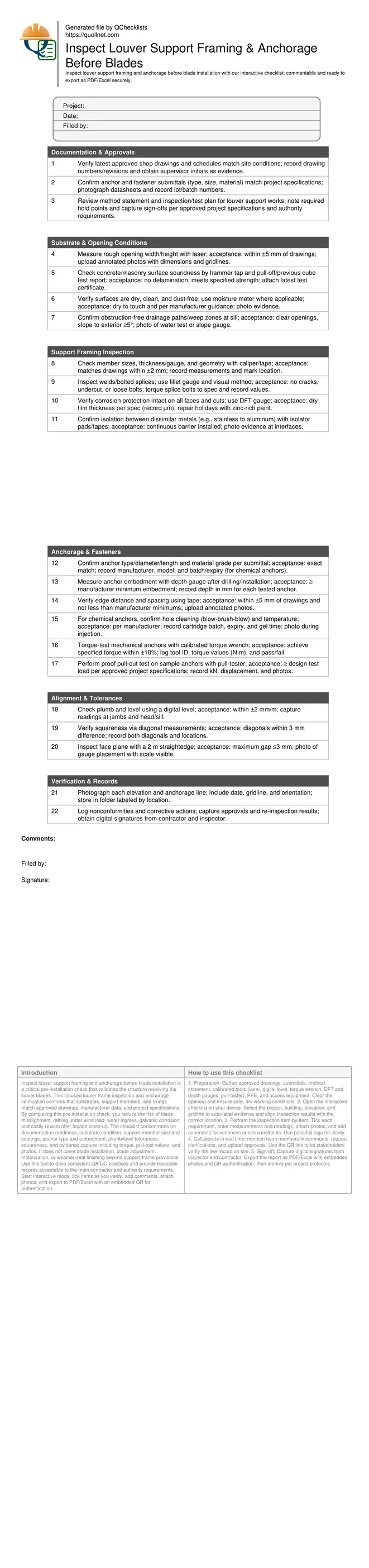
Definition: Inspect louver support framing and anchorage before blade installation ensures pre-installation structural readiness for louvers, targeted at site supervisors, QA/QC inspectors, and contractors, preventing rework and weather-infiltration failures.
- Verify framing sizes, alignment, and corrosion protection meet approved drawings.
- Confirm anchor type, embedment, torque, and spacing for required load paths.
- Document evidence with photos, readings, lot numbers, and digital sign-offs.
- Interactive, commentable checklist with export and QR code verification.
Inspect louver support framing and anchorage before blade installation is a critical pre-installation check that validates the structure receiving the louver blades. This focused louver frame inspection and anchorage verification confirms that substrates, support members, and fixings match approved drawings, manufacturer data, and project specifications. By completing this pre-installation check, you reduce the risk of blade misalignment, rattling under wind load, water ingress, galvanic corrosion, and costly rework after façade close-up. The checklist concentrates on documentation readiness, substrate condition, support member size and coatings, anchor type and embedment, plumb/level tolerances, squareness, and evidence capture including torque, pull-test values, and photos. It does not cover blade installation, blade adjustment, motorization, or weather-seal finishing beyond support-frame provisions. Use this tool to drive consistent QA/QC practices and provide traceable records acceptable to the main contractor and authority requirements. Start interactive mode, tick items as you verify, add comments, attach photos, and export to PDF/Excel with an embedded QR for authentication.
- Validate that louver support members, substrates, and anchors conform to approved drawings and manufacturer instructions before blades arrive. Reduce rework by confirming alignment, embedment, torque, and corrosion protection with measurable tolerances and documented evidence.
- Improve weather performance and durability by verifying plumb/level, squareness, face alignment, and drainage/weep functionality. Catch misaligned frames, inadequate edge distances, or incompatible metals before they cause leaks or premature coating failures.
- Interactive online checklist with tick, comment, and export features secured by QR code.
- Strengthen traceability and sign-off by logging torque readings, pull-test results, coating thickness, batch numbers, and photographs tagged by elevation and gridline. Generate sharable, time-stamped PDF/Excel reports for project records and authority submissions.
Documentation & Approvals
Substrate & Opening Conditions
Support Framing Inspection
Anchorage & Fasteners
Alignment & Tolerances
Verification & Records
What to Validate in Support Framing and Why It Matters
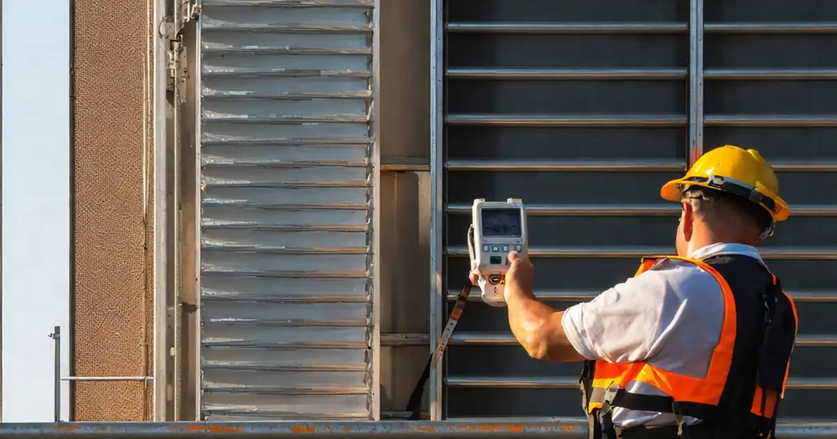
Before blades arrive, confirm the louver’s receiving frame can safely transmit wind and suction loads into the structure. Start with document control: the latest approved drawings, method statement, and submittals set acceptance targets for member sizes, anchor types, and protective finishes. On site, verify substrates are sound and dimensionally correct so frames fit without forced alignment. Check framing members with calipers and tapes for thickness and geometry, then inspect welds or bolted splices for continuity, tightness, and visible defects. Protective coatings are equally important; confirm dry film thickness where specified, and repair cuts with zinc-rich paint to prevent early corrosion. Finally, ensure isolation between dissimilar metals to avoid galvanic reactions. Acceptance cues include correct member sizes within ±2 mm, intact coatings at required thickness, clean interfaces with isolation pads, and documented approvals. These steps reduce rework, protect durability, and keep the installation sequence efficient when blades are fitted later.
- Confirm current drawings and submittals drive acceptance.
- Measure member sizes within ±2 mm tolerance.
- Verify coating thickness meets specified DFT.
- Ensure metal isolation to prevent galvanic corrosion.
- Record evidence with photos and readings.
Anchorage Selection, Installation Quality, and Field Testing
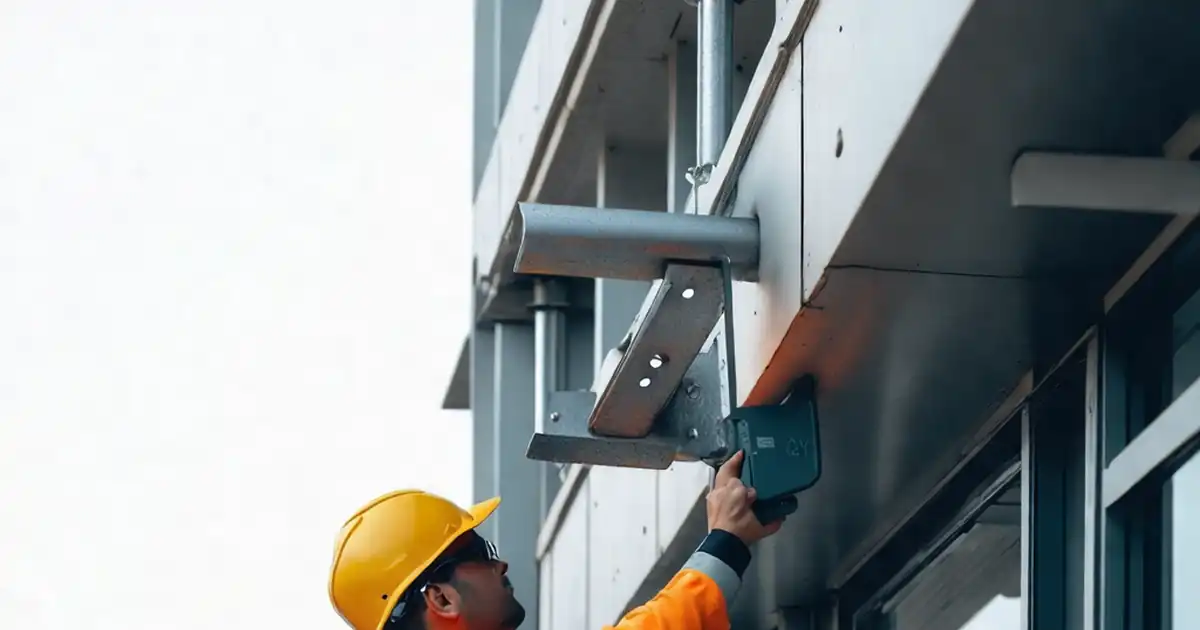
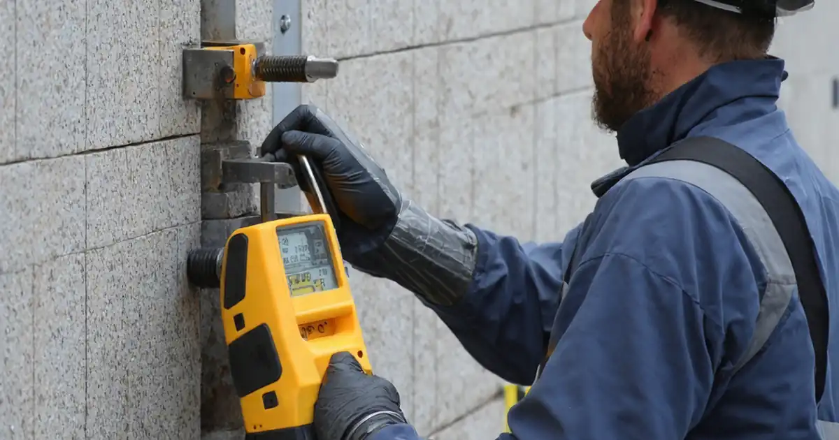
Anchors translate frame loads into concrete or masonry; small errors compound into failures. Match anchor type, diameter, and length to submittals, then check spacing and edge distances against drawings and manufacturer minimums. For mechanical anchors, verify hole diameter and depth, then torque to the specified value using a calibrated wrench and record results within ±10%. For chemical anchors, follow the blow-brush-blow sequence, confirm adhesive batch and expiry, and maintain installation temperature; measure embedment depth and record gel and cure times. Where required, use a pull-tester to verify a representative sample reaches or exceeds the design test load with acceptable displacement. Acceptance cues include correct embedment, compliant spacing/edge distances, torque values within range, and successful pull-out results. With evidence captured—photos, torque logs, kN readings, and batch numbers—you’ll have a defensible record that the anchorage can support the blades without slip, rattling, or creep under service loads.
- Match anchors to approved submittals.
- Maintain edge distance and spacing tolerances.
- Record torque and pull-out test values.
- Document adhesive batch and expiry for chemicals.
- Use calibrated tools; log tool IDs.
Alignment, Drainage, and Practical Jobsite Controls
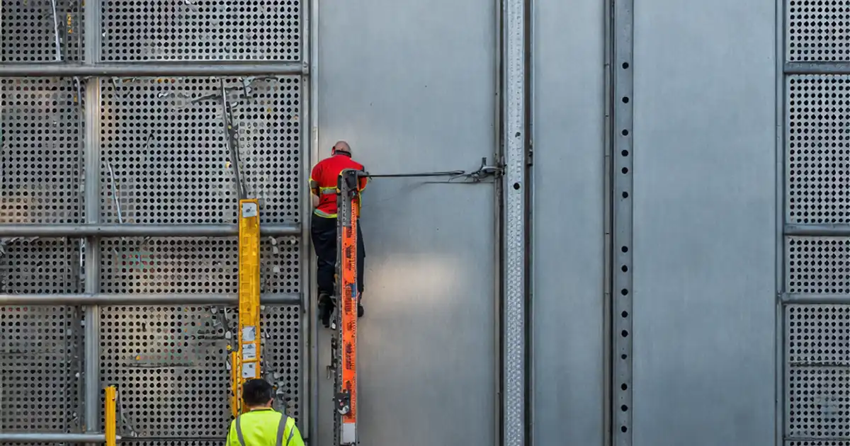
Accurate alignment ensures smooth blade fit, uniform reveals, and proper drainage. Measure plumb and level with a digital level and keep within ±2 mm/m; check squareness by comparing diagonals with a 3 mm maximum difference. Confirm the frame face is planar using a 2 m straightedge with a 3 mm maximum gap. At sill conditions, verify slope to the exterior (≥5°) and clear weep paths to avoid ponding or backflow during storms. On busy sites, standardize evidence capture: geo-tag photos, label locations by gridline and elevation, and mark inspected anchors with paint dots to avoid double work. Summarize deviations in the punch list and recheck only after corrective measures. These practices shorten close-out cycles and prevent late-stage clashes when façade sequencing tightens. Acceptance cues are numeric and visual: documented measurements, visible slopes and weeps, and signed inspection records stored with revision-controlled documents.
- Keep plumb/level within ±2 mm/m.
- Diagonals differ by no more than 3 mm.
- Face plane gap no greater than 3 mm.
- Sill slope outward ≥5° with clear weeps.
- Geo-tag photos and mark inspected points.
How to Use This Pre-Installation Inspection Checklist
- Preparation: Gather approved drawings, submittals, method statement, calibrated tools (laser, digital level, torque wrench, DFT and depth gauges, pull-tester), PPE, and access equipment. Clear the opening and ensure safe, dry working conditions.
- Open the interactive checklist on your device. Select the project, building, elevation, and gridline to auto-label evidence and align inspection results with the correct location.
- Perform the inspection item-by-item. Tick each requirement, enter measurements and readings, attach photos, and add comments for variances or site constraints. Use pass/fail tags for clarity.
- Collaborate in real time: mention team members in comments, request clarifications, and upload approvals. Use the QR link to let stakeholders verify the live record on site.
- Sign-off: Capture digital signatures from inspector and contractor. Export the report as PDF/Excel with embedded photos and QR authentication, then archive per project protocols.
Call to Action
- Start Checklist Tick off tasks, leave comments on items or the whole form, and export your completed report to PDF or Excel—with a built-in QR code for authenticity.
- Download Excel - Louver Support Framing & Anchorage Inspection
- Download PDF - Louver Support Framing & Anchorage Inspection
- View Image - Louver Support Framing & Anchorage Inspection
Cite & Embed
“Louver Support Framing & Anchorage Inspection by Quollnet”
with a link to
this source page.

FAQ
Question: What tolerances should I apply to frame plumb, level, and squareness?
Question: Do I need pull-out testing if I already torque-tested mechanical anchors?
Question: How do I prevent galvanic corrosion at the louver support frame?
Question: When should this inspection occur in the project sequence?
Related Articles
Broader reading and guidance connected to this checklist topic.

Plasticizers And Superplasticizers: How They Affect Concrete Slump
Impacted As-planned Analysis | Construction Delay Method

Related Checklists
Keep the workflow moving with nearby templates chosen from similar checklist content.