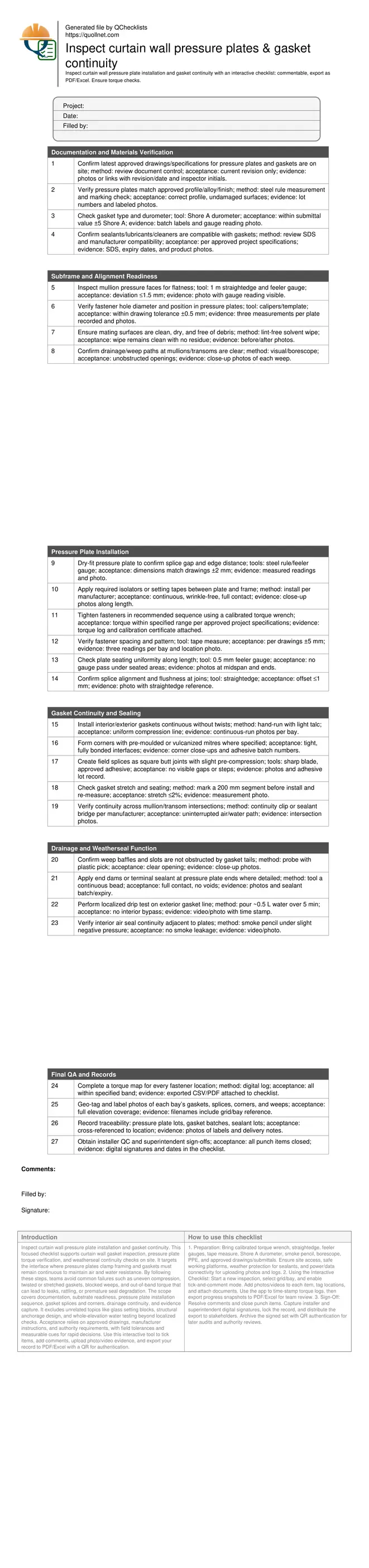
Inspect Curtain Wall Pressure Plate Installation and Gasket Continuity
Definition: Inspect curtain wall pressure plate installation and gasket continuity for façade inspectors and site QA, defining acceptance criteria, methods, and evidence to verify fastening torque, gasket seating, and uninterrupted weatherseal paths.
- Verify pressure plate fastening, splice alignment, and uniform seating tolerances.
- Confirm gasket continuity at corners and splices for airtight, watertight seals.
- Record torque readings, materials batches, and geo-tagged photo evidence for QA.
- Interactive, commentable, export to PDF/Excel; field access via project QR code.
Inspect curtain wall pressure plate installation and gasket continuity. This focused checklist supports curtain wall gasket inspection, pressure plate torque verification, and weatherseal continuity checks on site. It targets the interface where pressure plates clamp framing and gaskets must remain continuous to maintain air and water resistance. By following these steps, teams avoid common failures such as uneven compression, twisted or stretched gaskets, blocked weeps, and out-of-band torque that can lead to leaks, rattling, or premature seal degradation. The scope covers documentation, substrate readiness, pressure plate installation sequence, gasket splices and corners, drainage continuity, and evidence capture. It excludes unrelated topics like glass setting blocks, structural anchorage design, and whole-elevation water testing beyond localized checks. Acceptance relies on approved drawings, manufacturer instructions, and authority requirements, with field tolerances and measurable cues for rapid decisions. Use this interactive tool to tick items, add comments, upload photo/video evidence, and export your record to PDF/Excel with a QR for authentication.
- Assure uniform clamping and seal integrity by verifying torque sequencing, spacing, and plate seating with calibrated tools and measurable tolerances. Capture gasket material data, splice details, and corner treatments to prevent air and water infiltration while preserving drainage paths and long-term serviceability under movement.
- Implement a repeatable inspection flow: confirm current drawings and compatible materials, validate subframe readiness, tighten to specified torque, and check gasket continuity at transitions. Require photo-backed evidence, batch traceability, and digital signatures to close nonconformances swiftly and maintain auditable project records.
- Interactive online checklist with tick, comment, and export features secured by QR code.
- Reduce rework and latent defects by detecting twisted gaskets, misaligned splices, blocked weeps, and out-of-band torque early. Standardize acceptance cues such as feeler gauge passes, splice flushness, smoke pencil response, and documented torque maps per approved project specifications and authority requirements.
Documentation and Materials Verification
Subframe and Alignment Readiness
Pressure Plate Installation
Gasket Continuity and Sealing
Drainage and Weatherseal Function
Final QA and Records
Pressure plate installation: sequence, torque, and measurable acceptance cues
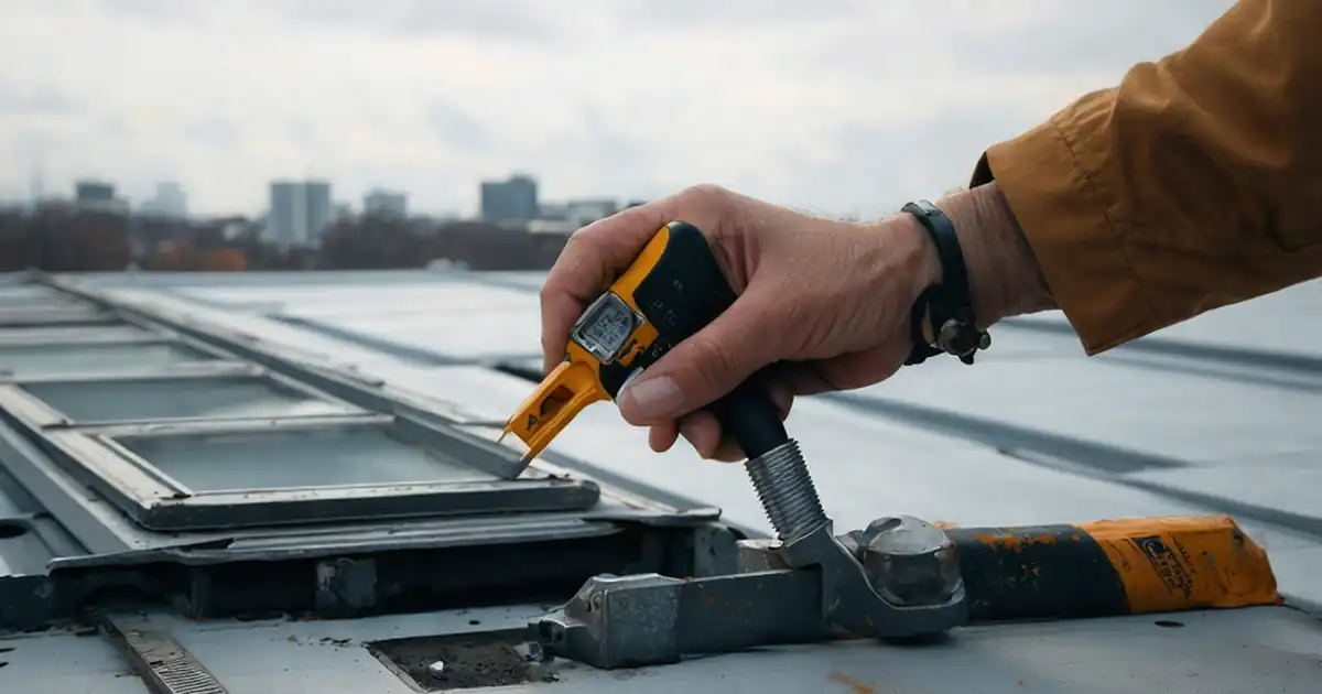
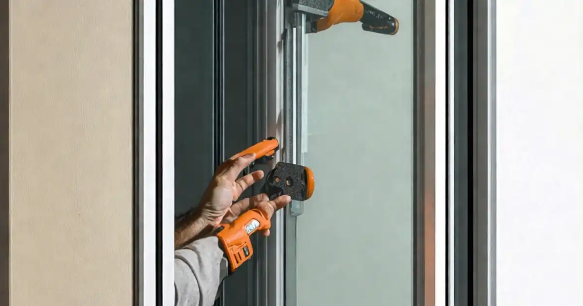
A reliable pressure plate installation starts with a clean, flat substrate and a consistent tightening sequence. Dry-fit to confirm edge distances and splice gaps, then place isolators or setting tapes as specified. Tighten fasteners from the center outward, alternating sides to distribute clamping evenly and avoid plate bow. Always use a calibrated torque wrench, logging each achieved value in a torque map. Verify spacing and patterns against the drawings, noting measured deviations. After tightening, confirm uniform seating using a 0.5 mm feeler gauge; a pass under the plate indicates uneven compression or debris. At splices, check flushness with a straightedge so the cover caps will seat correctly later. Document every reading and condition with geo-tagged photos to support acceptance. When in doubt, retorque after initial compression and recheck seating, particularly on longer lengths or temperature-sensitive installations. Acceptance should reference the manufacturer’s instructions and approved project specifications and authority requirements.
- Tighten center-out in a cross pattern for uniform clamping.
- Use a calibrated torque wrench with a current certificate.
- Record achieved torque and spacing against drawings.
- No 0.5 mm feeler pass under seated zones.
- Splices flush; offset not perceptible by touch.
Gasket continuity: corners, splices, compression, and field verification
Gasket continuity depends on proper material selection, careful handling, and clean interfaces. Confirm durometer and type, then install without twists or over-stretching. Corners should use pre-moulded or vulcanized mitres when detailed; otherwise make precise square butt joints with approved adhesive, adding slight pre-compression to eliminate gaps. Mark a 200 mm length before installation and remeasure after seating to keep stretch within acceptable limits. At intersections, ensure continuity clips or sealant bridges connect the air/water paths so drainage remains uninterrupted. Field verification can include a smoke pencil to detect air leakage, a light check behind corners to spot gaps, and close-up photos of splices and mitres. Localized drip testing over the exterior gasket line can validate seating without substituting for formal system testing. Acceptance relies on visible compression lines, tight joins, and documented, uninterrupted seal paths per approved project specifications and authority requirements.
- Install gaskets continuous, with no twists or roll-out.
- Use pre-moulded corners where specified for consistency.
- Square butt splices with slight pre-compression.
- Stretch within tolerance verified by marked segment.
- Seal paths continuous through intersections.
Evidence-driven QA: traceability, photos, and digital closeout
Effective façade QA ties each inspected element to verifiable data. Capture revision-controlled drawings, torque logs, and wrench calibration certificates. Photograph pressure plates, splices, corners, and weeps with geo-tags and grid/bay labels for unambiguous location mapping. Record material traceability: pressure plate production lots, gasket batch numbers, and sealant lot/expiry. Note acceptance cues in the checklist—measured gaps, feeler gauge outcomes, and observed smoke or drip tests. Any out-of-band torque, misaligned splices, or gasket gaps should trigger an immediate nonconformance, corrective action, and reinspection entry. Require installer QC and superintendent sign-offs to close each area. Export consolidated records to PDF/Excel for submittal, ensuring the QR-linked dataset remains accessible to reviewers. Align all acceptance criteria and methods with manufacturer guidance, approved project specifications, and authority requirements to avoid disputes and speed approvals.
- Geo-tag photos and label by grid/bay.
- Attach torque map and calibration proof.
- Log material lots and batch numbers.
- Issue NCRs and document closures promptly.
- Export PDF/Excel with QR-linked archive.
How to Use This Interactive Checklist
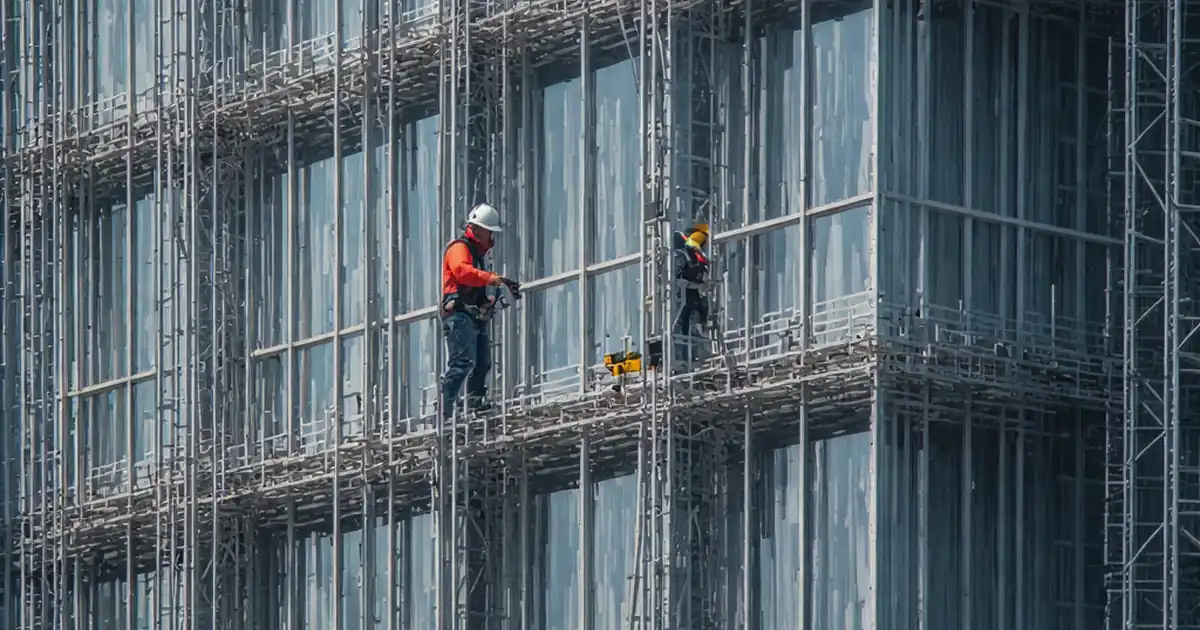
- Preparation: Bring calibrated torque wrench, straightedge, feeler gauges, tape measure, Shore A durometer, smoke pencil, borescope, PPE, and approved drawings/submittals. Ensure site access, safe working platforms, weather protection for sealants, and power/data connectivity for uploading photos and logs.
- Using the Interactive Checklist: Start a new inspection, select grid/bay, and enable tick-and-comment mode. Add photos/videos to each item, tag locations, and attach documents. Use the app to time-stamp torque logs, then export progress snapshots to PDF/Excel for team review.
- Sign-Off: Resolve comments and close punch items. Capture installer and superintendent digital signatures, lock the record, and distribute the export to stakeholders. Archive the signed set with QR authentication for later audits and authority reviews.
Call to Action
- Start Checklist Tick off tasks, leave comments on items or the whole form, and export your completed report to PDF or Excel—with a built-in QR code for authenticity.
- Download Excel - Curtain Wall Pressure Plate & Gasket Inspection
- Download PDF - Curtain Wall Pressure Plate & Gasket Inspection
- View Image - Curtain Wall Pressure Plate & Gasket Inspection
Cite & Embed
“Curtain Wall Pressure Plate & Gasket Inspection by Quollnet”
with a link to
this source page.

FAQ
Question: What torque should I use on curtain wall pressure plate fasteners?
Question: How can I quickly verify gasket continuity in the field?
Question: What common mistakes cause leaks around pressure plates and gaskets?
Question: Do I need a full water test after installing pressure plates and gaskets?
Related Articles
Broader reading and guidance connected to this checklist topic.

Is The Crack You See On Your Wall Serious Or Minor Cosmetic Issue?


Is It Important To Customize Your Qr Code And How To Do It?

Related Checklists
Keep the workflow moving with nearby templates chosen from similar checklist content.