Inspect Fixed Louver Blade Installation: Spacing & Orientation
Definition: Inspect fixed louver blade installation for spacing and orientation to guide site supervisors and QA teams in verifying uniform blade pitch, angle, and alignment on horizontal louvers during installation.
- Confirms blade pitch within tolerance across full panel width.
- Verifies orientation angle and plane alignment for consistent airflow.
- Uses calibrated tools: steel rule, inclinometer, laser, feeler gauges.
- Interactive, commentable checklist with export and QR code traceability.
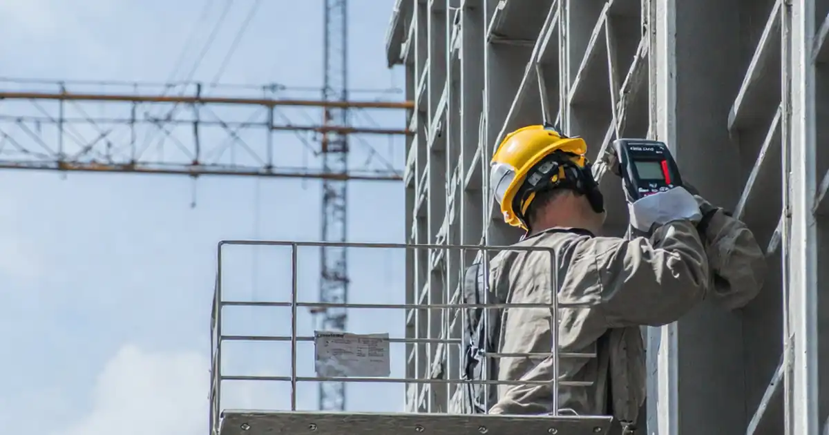
Inspect fixed louver blade installation for spacing and orientation is a focused quality-assurance task that ensures each horizontal blade meets specified pitch, alignment, and angle. This checklist targets uniform spacing, correct blade orientation, consistent reveals, and straightness across panels of extruded aluminum louvers. By concentrating on blade pitch, plane alignment, and angle verification, inspectors prevent rattle, binding, increased pressure drop, water entrainment, and visual irregularities. The scope covers installed fixed horizontal louvers only, using calibrated tools such as a digital inclinometer, steel rule, laser level, and feeler gauges; it excludes structural testing, sealant systems, and performance ratings, which must be verified separately per approved project specifications and authority requirements. Outcomes include verifiable measurements, time-stamped photos, and sign-offs that demonstrate conformance to approved shop drawings. Start in interactive mode: tick items as you inspect, add comments where deviations occur, attach photos and readings, and export your results to PDF/Excel with a secure QR code for traceable handover.
- Achieve uniform blade pitch and reliable airflow by verifying spacing, reveals, and cumulative stack height against approved shop drawings. Defined tolerances and calibrated tools help prevent binding, whistle, and misalignment while documenting readings and photo evidence for defensible quality records.
- Control aesthetic consistency and performance by confirming blade angle to horizontal with a digital inclinometer, checking straightness with a straightedge or laser, and validating panel-to-panel transitions. This reduces rework and ensures façade lines read true across long runs.
- Interactive online checklist with tick, comment, and export features secured by QR code. Use this to capture measurements, photos, and approvals on-site, then generate time-stamped reports for consultants and owners, tightening closeout timelines and improving audit readiness.
- Mitigate root causes of nonconformity—improper bracket spacing, loose fasteners, and uneven shimming—through targeted checks with torque wrenches, rules, and feeler gauges. Produce a punch list with unique IDs, corrective actions, and reinspection results, ensuring full compliance before handover.
Pre-Inspection and Setup
Blade Spacing Verification
Blade Orientation and Alignment
Supports and Fastenings
Documentation and Closeout
Measurement Strategy: Sampling, Datums, and Repeatability
Reliable louver assessments start with stable datums and a repeatable method. Establish level and plumb references using a calibrated laser to eliminate frame-induced bias. Measure blade pitch at consistent left/centre/right positions, and extend checks to panel edges, where misalignment often concentrates. To balance thoroughness and productivity, inspect 100% of edges and at least 10% of interior blades per bay, increasing the sample when variability is detected. For angle checks, use a digital inclinometer with known calibration and measure each selected blade at both ends and mid-span. Record conditions—particularly wind gusts and temperature—when significant movement or thermal growth could influence readings. Always link measurements to panel IDs and photo evidence for traceability. When nonconformities appear, immediately flag with unique IDs and annotate their exact positions on an elevation sketch. This systematic approach supports swift corrections and consistent results across crews, shifts, and elevations, reducing rework and enabling confident consultant sign-off.
- Set laser datums to control pitch and angle references.
- Measure edges 100%; sample interior blades at ≥10%.
- Take inclinometer readings at ends and mid-span.
- Capture time-stamped photos tied to panel IDs.
- Escalate sampling when variability is observed.
Tools, Tolerances, and Practical Acceptance Cues
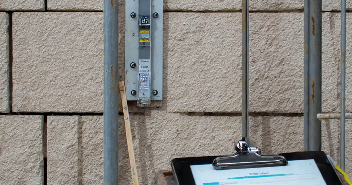
Select tools that match the resolution of your tolerances. A steel rule with clear millimetre graduations and 0.5 mm feeler gauges suit most pitch checks. Digital inclinometers should read to 0.1° and be recently calibrated. Straightness can be confirmed with a 1 m straightedge and supplementary feelers. Typical acceptance cues include pitch within ±2 mm, cumulative stack height within ±5 mm, and orientation within ±1°. Where project-specific values differ, apply those per approved project specifications and authority requirements. Plane alignment should show no gaps exceeding 2 mm under the straightedge over 1 m, and panel-to-panel offsets should remain under 3 mm against a laser line. Document torque values for blade-to-bracket connections and verify shim materials are non-compressible so spacing does not drift post-handover. Combine readings with annotated photos to create an evidence trail that withstands audits and supports warranty claims.
- Match tool resolution to tolerance targets.
- Use 0.1° digital inclinometers, recently calibrated.
- Pitch ±2 mm; angle ±1° unless drawings state otherwise.
- Document torque values and calibration certificates.
- Validate straightness with a 1 m straightedge.
Common Nonconformities and Targeted Corrections
Frequent issues include drifting pitch caused by uneven bracket spacing, inconsistent reveals from skewed frames, and angle deviations due to incomplete clip engagement. Twisted blades can stem from over-torqued fasteners or stacked shims. Address root causes, not symptoms: adjust bracket locations to restore c/c spacing; re-square and re-plumb frames before fine-tuning blades; reseat locking clips to prevent rotation; replace compressible shims with non-compressible options, keeping stack thickness minimal. If thermal clearances are tight, relieve interference points so blades move freely without contact. After corrections, repeat original measurements and document before/after conditions, linking photos to panel IDs. Share a concise punch list with responsible parties and deadlines; this maintains momentum and avoids partial fixes across large elevations. Consistent reinspection protocols reduce callbacks and keep handover timelines on track while preserving the visual rhythm intended by the architect.
- Fix bracket spacing to stabilize blade pitch.
- Square frames before adjusting blades.
- Fully seat clips; eliminate blade rotation.
- Use non-compressible shims, minimal stack.
- Retest and document before/after evidence.
How to Use This Louver Spacing & Orientation Checklist
- Preparation: Calibrate the laser level, digital inclinometer (0.1° resolution), steel rule, feeler gauges, and torque wrench. Verify tool certificates are current and upload them to the checklist.
- Preparation: Retrieve approved drawings/specifications and louver submittals. Mark bay and panel IDs on the frame. Establish level/plumb datums with a laser and note ambient conditions.
- Preparation: Ensure safe access (platforms, harnesses) and adequate lighting. Clean blade surfaces where gauges and rules will contact to avoid false readings.
- Using the Interactive Checklist: Start interactive mode, select location and panel IDs, then tick items as you proceed. Enter measurements in SI units and attach time-stamped photos.
- Using the Interactive Checklist: Add comments for deviations, tag responsible parties, and set due dates. Export interim reports to PDF/Excel for coordination meetings.
- Sign-Off: After all items pass, generate a punch list summary showing closed items, measurement logs, and photos. Secure a QR code for authentication and traceability.
- Sign-Off: Collect digital signatures from installer, QA, and consultant. Export the final package as PDF/Excel and archive it in project records.

Call to Action
- Start Checklist Tick off tasks, leave comments on items or the whole form, and export your completed report to PDF or Excel—with a built-in QR code for authenticity.
- Download Excel - Fixed Louver Blade Spacing & Orientation Inspection
- Download PDF - Fixed Louver Blade Spacing & Orientation Inspection
- View Image - Fixed Louver Blade Spacing & Orientation Inspection
Cite & Embed
“Fixed Louver Blade Spacing & Orientation Inspection by Quollnet”
with a link to
this source page.

FAQ
Question: What tolerances are typical for blade pitch and angle on fixed horizontal louvers?
Question: How do I accurately measure the louver blade angle on site?
Question: How many blades should I sample per bay for orientation and spacing?
Question: What should I do if the frame is out of level or plumb?
Question: Why are shims and fastener torque critical to maintaining spacing and orientation?
Related Articles
Broader reading and guidance connected to this checklist topic.


Is It Important To Customize Your Qr Code And How To Do It?


Related Checklists
Keep the workflow moving with nearby templates chosen from similar checklist content.