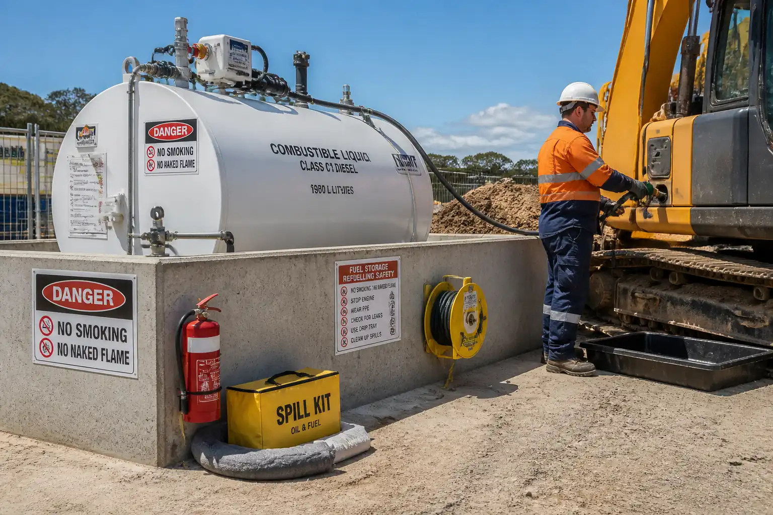

Method Statement: Temporary Fuel Storage and Equipment Refueling Operations – Method Statement
AI-assisted method statement with matching ITP, PDF download, and Excel export.
More than a static template
Unlike a downloadable Word or PDF template, this method statement is an AI-assisted editable starting point connected directly to a matching Inspection and Test Plan. Every section is structured, project-adaptable, and ready to export.
- AI-assisted drafting — Customize every section with AI for your specific project scope.
- Linked ITP — A matching inspection and test plan is generated alongside the method statement.
- Multiple export formats — Download as a formatted PDF or editable Excel spreadsheet.
- Editable starting point, not a final document — Review, verify, and adjust all content against your project requirements before use.
Static template vs. Quollnet workflow
| Feature | Static template | Quollnet |
|---|---|---|
| Project-specific content | Manual fill-in required | AI-assisted customization |
| Linked ITP | Separate document, no link | Matching ITP included |
| Export formats | Usually PDF only | PDF and Excel |
| Structured sections | Free-form layout | 13 standardized sections |
| Saved to your account | Local file only | Cloud-saved, reusable |
| Content accuracy | You verify everything | AI-assisted, you still verify |
| Cost | Often free but time-intensive | Free to customize and download |
What you can customize
When you save this method statement to your account, every section becomes editable. The following 13 sections are included:
- Scope — Defines the activity and its boundaries.
- References — Standards, specifications, and drawings.
- Responsibilities — Roles and accountabilities.
- Resources — Labour, plant, and equipment summary.
- Materials — Materials and compliance requirements.
- Equipment — Tools and equipment details.
- Prerequisites — Hold points and pre-conditions.
- Method sequence — Step-by-step construction sequence.
- Safety controls — HSE risk controls and PPE.
- Environmental controls — Environmental mitigation measures.
- QA/QC — Quality inspection and test requirements.
- ITP — Inspection and Test Plan table (has its own page).
- Attachments — Referenced drawings and documentation.
Why this method statement is used
This method statement is used to define and communicate the approved procedure for carrying out method statement: temporary fuel storage and equipment refueling operations on site. It ensures the work is planned in advance, the correct resources and controls are in place, and all personnel understand responsibilities, sequence, quality requirements, and safety controls before work begins. It aligns site execution with the documented scope and acceptance expectations.
Who uses this method statement
This method statement is used by contractors, site supervisors, project engineers, QA/QC engineers, HSE officers, consultants, and client representatives. It serves as a shared reference for planning, execution, supervision, inspection, and approval of the activity on site.
When it is prepared and submitted
The method statement is prepared before the work activity starts and submitted as part of the pre-construction documentation package for review and approval.
Who reviews or approves it
The method statement is usually submitted to the client representative, consultant, resident engineer, or project management consultant for review and approval before the work commences.
Important approval note
This method statement is an AI-assisted editable starting point, not a pre-approved document. Before use on any project, all content must be reviewed and approved by the relevant parties (superintendent, principal contractor, or client representative) in accordance with your contract and project quality plan.
For example: if your specification requires a departure from a referenced standard, that departure must be documented and approved separately — this method statement will not capture that automatically. Always verify against your applicable drawings, specifications, and regulatory requirements.
Method statement content
Scope
Overview
This method statement defines the requirements and step-by-step procedure for establishing and operating temporary fuel storage and refueling areas on . It covers:
- Selection, placement, and installation of aboveground fuel storage tanks (ASTs)
- Bunding/secondary containment and impermeability verification
- Fire prevention and emergency preparedness
- Fuel transfer systems (pumps, hoses, nozzles, meters) and earthing/bonding
- Refueling operations for plant, vehicles, and equipment
- Spill prevention, containment, and response
- Environmental monitoring and controlled discharge of bunded rainwater
- Permit-to-work (PTW) controls and supervision
- Inspection and testing plan (ITP), QA/QC verification, and records
Exclusions
- Entry into tanks or confined spaces (separate confined space permit and method required)
- Permanent fuel facility design approval by Authorities Having Jurisdiction (AHJ)
- Fuel quality certification beyond supplier COA (additional testing if required by project specs)
Key Performance Objectives
- Zero spills to ground or water
- No fire/explosion incidents
- Full traceability of fuel receipts, issues, and inspections
- Compliance with applicable codes and project HSE/Environmental plans [Verify per project HSE plan and local regulations]
References
| Document Type | Reference / Number | Revision | Notes |
|---|---|---|---|
| Code/Standard | NFPA 30 | ||
| Recommended Practice | API RP 2003; NFPA 77 | ||
| Code/Standard | NFPA 10 | ||
| Standard/Listing | BS EN 12285; UL 142; UL 2085 | Select per local approval basis [Verify]. | |
| Standard | EN 13616-1 | ||
| Standard | ISO 1825 or EN 1360 | Use hoses suitable for diesel/gasoline as applicable. | |
| Guidance | CIRIA C736 | Benchmark for bund water test and detailing. | |
| Standard | ISO 14001; ISO 45001 | ||
| Standard | EN 590 | Alternate: ASTM D975 in some regions. | |
| Contract/Regulatory | [Insert specific documents] | Site-specific values to be verified. |
Responsibilities
| Role | Responsibility | Name / Party |
|---|---|---|
| Project Manager | Approve method, ensure budgets and resources. | Contractor |
| HSE Manager | Issue PTWs, conduct audits. | Contractor |
| Site Engineer | Check levels/compaction; coordinate tests. | Contractor |
| Mechanical Supervisor | Ensure correct assembly, leak testing. | Contractor |
| Electrical Supervisor | Hazardous area compliance [Verify]. | Contractor |
| QA/QC Engineer | Verify hold/witness points. | Contractor |
| Fuel Controller | Execute SOPs; maintain logs. | Contractor |
| Environmental Officer | Interface with regulators. | Contractor |
| Lifting Supervisor | Safe lifting execution. | Contractor |
| Third-Party | Independent verification. | Independent |
Resources
| Resource Type | Description | Quantity | Remarks |
|---|---|---|---|
| Labor | Fuel Controller/Operator (1–2) | 1–2 | |
| Labor | HSE Officer (1), Fire Watch (as needed during transfers or hot works nearby) | 1–2 | |
| Labor | Supervision for installation and commissioning | 3 | |
| Labor | Monitoring and records | 1 |
Materials
| Material | Specification / Grade | Quantity | Remarks |
|---|---|---|---|
| AST | UL 142/BS EN 12285 | 1–2 | |
| Concrete/HDPE | CIRIA C736 | As per design | |
| Pumps/Hoses | ISO 1825/EN 1360 | 1 set | |
| Earthing kit | API RP 2003/NFPA 77 | As required | |
| Instruments | EN 13616-1 | 1 set/tank | |
| FFE | NFPA 10 | As per fire plan [Verify] | |
| Spill kits | Project spill plan | ≥1 per refuel point [Verify] | |
| Signage | Local regs | Complete set |
Equipment
| Equipment | Capacity / Type | Quantity | Inspection Required |
|---|---|---|---|
| Crane/Forklift | ≥25 t [Verify] | 1 | Yes |
| Compactor | 1 | Yes | |
| Mixer/Tools | As needed | Yes | |
| Pump set | 1–2 | Yes | |
| Testers | 1 set | Yes | |
| Test kit | 1 | Yes | |
| Set | Yes |
Prerequisites
Pre-Start Requirements
- Approved method statement, risk assessment, and ITP.
- Site layout drawing showing tank location, exclusion zones, traffic management, fire points, and drainage paths.
- Permits-to-work (PTW): Fuel handling/transfer, lifting operations, electrical works; hot work permit for any ignition sources within the fuel area. [Verify per project HSE plan and local regulations]
- Underground/overhead utility survey and clearance; mark no-dig zones.
- Ground bearing verification for tank and bund (geotechnical recommendation or plate load test). Minimum allowable bearing pressure to exceed anticipated service load with factor of safety ≥3 [Verify].
- Emergency Response Plan (ERP) including spill response, fire response, and communication tree; drill scheduled before first fuel delivery.
- Competency and training records for Fuel Operator, Fire Watch, and lifting/electrical teams.
- Vendor documentation for tank, pumps, hoses, nozzles, meters, overfill devices, vents/flame arrestors.
- Calibration certificates for meters and instruments.
- Environmental approvals for temporary storage and controlled discharge of bunded rainwater (if applicable).
Method Sequence
| Step | Activity | Description | Responsibility | Inspection / Hold Point |
|---|---|---|---|---|
| 1 | Site Layout and Marking | Set out tank pad, bund footprint, access/egress, and 24/7 security fencing. Establish no-smoking boundary and emergency routes. | Site Engineer | Survey check |
| 2 | Base Preparation | Excavate/trim; place 150–200 mm compacted crushed aggregate (well-graded) and blinding. For concrete pads, cast slab per design with surface finish to SR2 and slope 1–2% to sump/drain within bund. | Site Engineer | FDT/plate load (as required) |
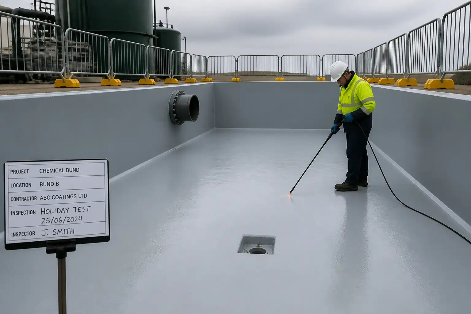
| 3 | Bunding/Containment Construction | Construct RC bund walls/floor or install HDPE liner over smooth subgrade with geotextile underlay; integrate upstand and sealed joints; install sump for rainwater collection. | Site Engineer | Visual; liner spark test (if used) |
| 4 | Bunding Capacity/Integrity Test | Hydrostatic test by filling bund with clean water to design high level; retain 24 h; mark gauge points and temperature; inspect for leaks/wet spots. | QA/QC Engineer | Witness (Client/TPA) |
| 5 | Tank Delivery and Receipt Inspection | Receive tank on level ground; check nameplate, certification, coatings, fittings, vents, interstitial monitor, and damage. | Mechanical Supervisor | Visual |
| 6 | Lifting and Placement | Rig tank using certified slings/spreader as per lift plan; place onto level supports or plinths; install anchor bolts/clips if required by design. | Lifting Supervisor | Pre-lift; spotter in place |
| 7 | Separation/Exclusion Zone Verification | Measure distances to buildings, property lines, ignition sources, storm drains; erect barriers and signage. | HSE Manager | Tape survey |
| 8 | Piping/Hose Installation | Install suction/dispense lines, filter/water separator, meter, and automatic shut-off nozzle; minimize joints; protect from traffic; provide drip trays at hose/nozzle storage. | Mechanical Supervisor | Visual |
| 9 | Earthing/Bonding Installation | Install earth rods and bonding cables to tank, pump, and dispensing nozzle; provide bonding clip for vehicle/equipment during refueling. | Electrical Supervisor | Continuity test |
| 10 | Overfill/Vent/Alarm Setup | Fit overfill valve/probe, high-level alarm, normal/emergency vents with flame arrestor as required by listing/code. | Mechanical Supervisor | Functional |
| 11 | Fire Protection and Emergency Setup | Install extinguishers, spill kits, emergency stop, call points, and illuminated signage; ensure access and wind-direction indicator. | HSE Manager | HSE check |
| 12 | Initial Fuel Receipt and Commissioning | Under PTW, receive first delivery. Bond tanker to tank; verify earthing; slow fill; check for leaks at all joints; verify meter and interstitial monitor; record initial dip/ullage. | Fuel Controller | Witness by QA/QC |
| 13 | Refueling Operations SOP | Position plant on level ground; engine off (unless OEM specifies otherwise); apply parking brake; chock as needed; place drip tray; bond nozzle to equipment fill; open cap slowly; refuel at controlled rate; maintain watch; stop at 95% capacity; wipe drips; replace caps; log volumes. | Fuel Controller | Spot checks |
| 14 | Bund Water Management | After rain, visually check for sheen; use portable oil-water separator or absorbents; only discharge clean water via controlled point with authorization. | Environmental Officer | Visual/pH (if required) |
| 15 | Routine Inspection & Maintenance | Daily: hoses/nozzle leaks, spill kits, earthing lead, signage. Weekly: bund, anchors, vents, extinguisher gauge. Monthly: meter verification, bonding resistance, hose pressure test visual. 6-monthly: full hose pressure test; annual: extinguisher service, tank inspection. | QA/QC Engineer | Per ITP |
| 16 | Spill Response | Stop source; activate emergency stop; deploy absorbents/booms; protect drains; notify per ERP; recover waste to UN-rated drums; report and investigate. | HSE Manager | Post-incident review |
Health, Safety, and Fire Controls
Hazard Controls (Task-Specific)
- Hazard: Flammable/combustible liquid exposure and ignition
- Likely Consequence: Fire, flash fire, burns, property damage
- Engineering/Procedural Control: Maintain separation distances per NFPA 30/local code [Verify]; no ignition sources within exclusion zone; use intrinsically safe equipment if hazardous area classification dictates [Verify]; install emergency stop and overfill protection; keep vents clear and fit flame arrestors if required by listing.
- Required PPE: Anti-static clothing, safety glasses, nitrile gloves, safety boots; flame-resistant coveralls during hot works nearby.
- Collective Measures: No-smoking zone; barriers and signage; dedicated fire points with ABC and foam extinguishers.
-
Inspection/Permit/Supervision: Fire watch during transfers/hot works; PTW for fuel handling/hot work; monthly extinguisher inspections per NFPA 10.
-
Hazard: Static electricity during fuel transfer
- Likely Consequence: Ignition of vapors
- Engineering/Procedural Control: Bond tanker to tank and nozzle to equipment prior to opening caps; verify bonding resistance <10 Ω [Verify]; maintain fill pipe contact during fueling; control fill velocity to minimize splash.
- PPE: Anti-static footwear and garments; gloves; eye protection.
- Collective Measures: Bonding reels/clamps at all points; anti-splash nozzles.
-
Inspection/Permit/Supervision: Periodic resistance testing; supervision by Fuel Controller.
-
Hazard: Spill to ground or drains
- Likely Consequence: Soil/groundwater contamination; slip hazard
- Engineering/Procedural Control: Impermeable bund with capacity ≥110% of largest tank [Verify]; drip trays at all refueling points; drain seals/booms available; routine hose inspection; use automatic shutoff nozzles.
- PPE: Gloves, eye protection, boots with slip-resistant soles.
- Collective Measures: Spill kits at point of use; drain covers pre-positioned; training and drills.
-
Inspection/Permit/Supervision: Daily checks; environmental permit for discharge; spill reporting per ERP.
-
Hazard: Vehicle/plant movement around fuel area
- Likely Consequence: Collision, impact damage to tank/lines
- Engineering/Procedural Control: One-way traffic plan; crash barriers or bollards to protect tank/pipework; designated parking/refuel bay with level surface.
- PPE: Hi-vis, hard hat, boots.
- Collective Measures: Banksman for reversing; speed limits; lighting for night work.
-
Inspection/Permit/Supervision: Traffic management plan approval; weekly checks on barriers/signs.
-
Hazard: Lifting operations (tank placement)
- Likely Consequence: Dropped load, crushing
- Engineering/Procedural Control: Approved lift plan; certified crane and rigging; exclusion zone; taglines; level landing area.
- PPE: Hard hat, gloves, boots, hi-vis.
- Collective Measures: Barricades and spotters; radio comms.
-
Inspection/Permit/Supervision: Lifting permit; pre-lift meeting; crane inspection records.
-
Hazard: Manual handling of hoses
- Likely Consequence: Strains, sprains
- Engineering/Procedural Control: Hose reels and supports; team lift for long hoses; limit hose length to operational need.
- PPE: Gloves, boots.
- Collective Measures: Ergonomic training.
-
Inspection/Permit/Supervision: Supervisor oversight; periodic review.
-
Hazard: Exposure to fumes
- Likely Consequence: Headache, nausea
- Engineering/Procedural Control: Outdoor refueling only; avoid prolonged idling; ensure cross-ventilation.
- PPE: As needed, half-mask respirator with organic vapor cartridges if specified by HSE for confined/poorly ventilated areas [Verify].
- Collective Measures: Prohibit enclosed area fueling.
-
Inspection/Permit/Supervision: HSE monitoring.
-
Note: No tank internal entry is permitted under this method. Any tank entry will require a separate confined space procedure, gas testing, and permit.
Environmental Controls
Pollution Prevention and Monitoring
- Secondary Containment: Bund capacity ≥110% of largest tank or 25% of total volume [Verify per local regulations]; impermeable construction per CIRIA C736; joints sealed; penetrations booted.
- Drainage Control: Isolate bund from stormwater system; install lockable drain valve to authorized discharge point; keep normally closed and tagged; maintain drain covers near nearby catch basins.
- Rainwater Management: Inspect for sheen before any discharge; use absorbent pads/portable separators to remove hydrocarbons; record volume, date, time, and authorizing person.
- Spill Response: Maintain spill kits sized to worst credible spill at the point; train crew; drill at least quarterly [Verify].
- Waste Management: Segregate contaminated absorbents/soil as hazardous waste; store in UN-rated drums with labels; arrange licensed transport and disposal; keep manifests.
- Soil and Water Monitoring: After any spill >20 L [Verify], take photos, record GPS, and perform soil screening; groundwater monitoring if required by permit.
- Air/Noise: Minimize idling; maintain equipment to reduce emissions; use acoustic measures if near receptors [Verify].
- Housekeeping: Keep fill/dispense area clean, free of debris; immediate cleanup of drips; maintain clear access to firefighting and spill response equipment.
- Documentation: Maintain environmental logbook, bund inspection forms, discharge records, waste transfer notes, and incident reports.
QA/QC
Quality Assurance and Quality Control Plan
- Documentation Control: Maintain current approvals for method, risk assessment, ITP, drawings, and vendor data. Obsolete copies removed from use.
- Material Verification: Check tank and equipment certifications (UL/EN), liner certificates, hose ratings, overfill devices, and extinguishers per NFPA 10.
- Testing and Acceptance:
- Base compaction: ≥95% MDD [Verify]; records of tests.
- Bund integrity test: 24 h water test, ≤0.5% corrected loss [Verify].
- Hose/line pressure test: 1.5× operating pressure, hold 10 min, zero visible leakage/pressure loss [Verify].
- Earthing/bonding: Resistance <10 Ω between bonded components [Verify].
- Overfill/level alarms: Trip at setpoint (90–95% typical) with audible/visual indication [Verify].
- Meter verification: Check against prover can or calibrated reference monthly; variance ≤1% [Verify].
- Calibration: Maintain calibration certificates for meters, test gauges, and electrical testers; do not use out-of-date instruments.
- Nonconformance Control: Log NCRs; implement corrective actions; verify closure before operation.
- Training and Competence: Keep training matrix and operator authorizations current; toolbox talks prior to first fill and quarterly thereafter [Verify].
- Records Retention: Keep ITP records, checklists, calibration, bund discharge logs, fuel reconciliation, waste manifests, and incident reports for ≥3 years or as per contract [Verify].
Attachments
- Layout drawing of temporary fuel storage and refueling area (with dimensions, clearances, and traffic plan)
- Lifting plan and rigging certificates for tank placement
- Tank datasheets, certifications (UL/EN), and nameplate photos
- Pump, hose, nozzle, meter, and overfill device datasheets and manuals
- Earthing/bonding schematic and test records
- Bund design details and hydrostatic test certificate
- Fire risk assessment and extinguisher schedule
- Spill response plan and SDS for fuels
- PTW templates (fuel transfer, hot work, lifting, electrical)
- Daily/Weekly/Monthly inspection checklists and fuel reconciliation log templates
This content is a read-only public reference. Download or customize to get an editable version.
ITP preview
The first inspection activities from the linked ITP for Method Statement: Temporary Fuel Storage and Equipment Refueling Operations:
| Activity | Inspection / Test | Acceptance Criteria | Responsibility | Record |
|---|---|---|---|---|
| Base preparation and compaction | Field density/plate load (if required) | Compaction ≥95% MDD; level tolerance ±10 mm; slope 1–2% [Verify]. | Site Engineer / QA/QC | FDT reports; survey records |
| Bund construction and liner installation | Visual/spark test | No defects; full continuity; penetrations sealed. | Site Engineer / QA/QC / Third-Party (as required) | Inspection report |
| Bund hydrostatic integrity/capacity test | 24 h water test | No visible leakage; corrected loss ≤0.5%; capacity per requirement [Verify]. | QA/QC / Client Rep | Bund test certificate |
Showing 3 of 12 inspection activities. View full ITP →
Related Inspection and Test Plan
An Inspection and Test Plan (ITP) is available for Method Statement: Temporary Fuel Storage and Equipment Refueling Operations. The ITP defines the inspection activities, acceptance criteria, hold and witness points, responsible parties, and records required to verify the work described in this method statement.
View the Method Statement: Temporary Fuel Storage and Equipment Refueling Operations ITP →Frequently asked questions
Continue with related Quollnet resources connected to this method statement.