
Method Statement: Installation and Commissioning of Electric/Diesel Fire Pump and Jockey Pump System – Method Statement
AI-assisted method statement with matching ITP, PDF download, and Excel export.
More than a static template
Unlike a downloadable Word or PDF template, this method statement is an AI-assisted editable starting point connected directly to a matching Inspection and Test Plan. Every section is structured, project-adaptable, and ready to export.
- AI-assisted drafting — Customize every section with AI for your specific project scope.
- Linked ITP — A matching inspection and test plan is generated alongside the method statement.
- Multiple export formats — Download as a formatted PDF or editable Excel spreadsheet.
- Editable starting point, not a final document — Review, verify, and adjust all content against your project requirements before use.
Static template vs. Quollnet workflow
| Feature | Static template | Quollnet |
|---|---|---|
| Project-specific content | Manual fill-in required | AI-assisted customization |
| Linked ITP | Separate document, no link | Matching ITP included |
| Export formats | Usually PDF only | PDF and Excel |
| Structured sections | Free-form layout | 13 standardized sections |
| Saved to your account | Local file only | Cloud-saved, reusable |
| Content accuracy | You verify everything | AI-assisted, you still verify |
| Cost | Often free but time-intensive | Free to customize and download |
What you can customize
When you save this method statement to your account, every section becomes editable. The following 13 sections are included:
- Scope — Defines the activity and its boundaries.
- References — Standards, specifications, and drawings.
- Responsibilities — Roles and accountabilities.
- Resources — Labour, plant, and equipment summary.
- Materials — Materials and compliance requirements.
- Equipment — Tools and equipment details.
- Prerequisites — Hold points and pre-conditions.
- Method sequence — Step-by-step construction sequence.
- Safety controls — HSE risk controls and PPE.
- Environmental controls — Environmental mitigation measures.
- QA/QC — Quality inspection and test requirements.
- ITP — Inspection and Test Plan table (has its own page).
- Attachments — Referenced drawings and documentation.
Why this method statement is used
This method statement is used to define and communicate the approved procedure for carrying out method statement: installation and commissioning of electric/diesel fire pump and jockey pump system on site. It ensures the work is planned in advance, the correct resources and controls are in place, and all personnel understand responsibilities, sequence, quality requirements, and safety controls before work begins. It aligns site execution with the documented scope and acceptance expectations.
Who uses this method statement
This method statement is used by contractors, site supervisors, project engineers, QA/QC engineers, HSE officers, consultants, and client representatives. It serves as a shared reference for planning, execution, supervision, inspection, and approval of the activity on site.
When it is prepared and submitted
The method statement is prepared before the work activity starts and submitted as part of the pre-construction documentation package for review and approval.
Who reviews or approves it
The method statement is usually submitted to the client representative, consultant, resident engineer, or project management consultant for review and approval before the work commences.
Important approval note
This method statement is an AI-assisted editable starting point, not a pre-approved document. Before use on any project, all content must be reviewed and approved by the relevant parties (superintendent, principal contractor, or client representative) in accordance with your contract and project quality plan.
For example: if your specification requires a departure from a referenced standard, that departure must be documented and approved separately — this method statement will not capture that automatically. Always verify against your applicable drawings, specifications, and regulatory requirements.
Method statement content
Scope
Work Summary
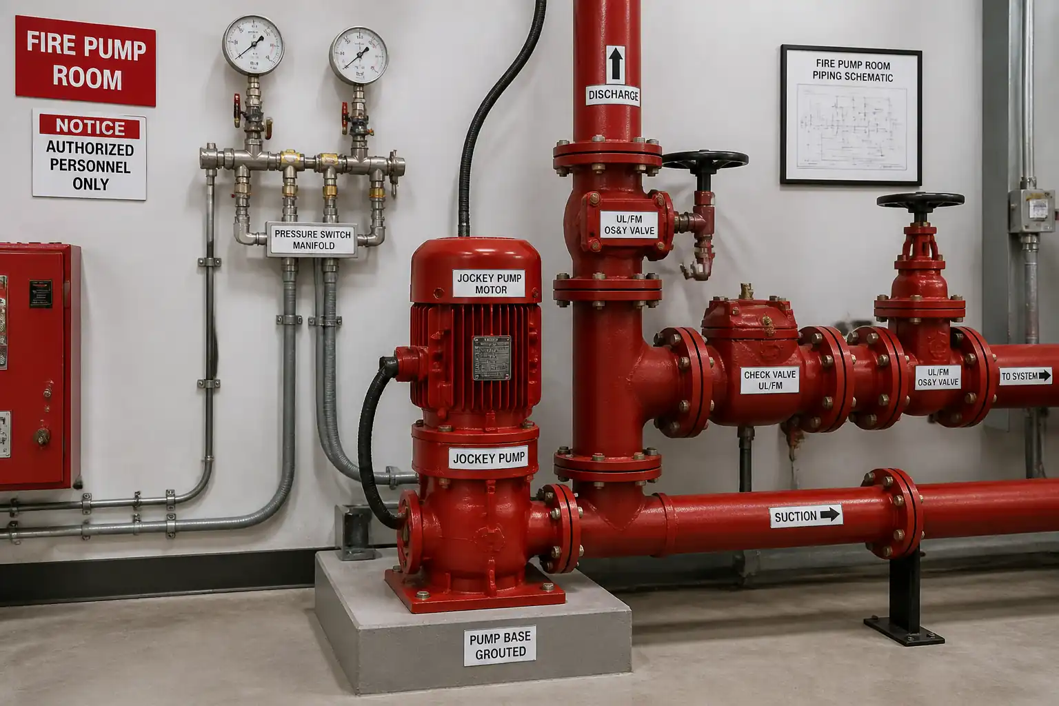
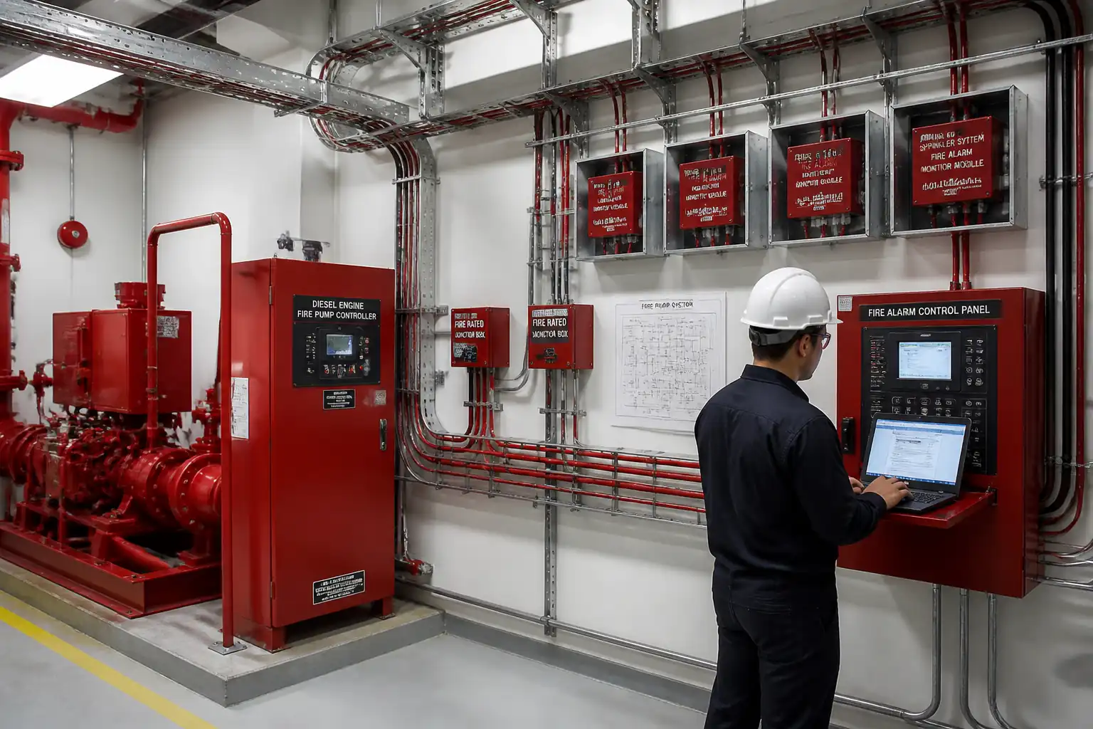
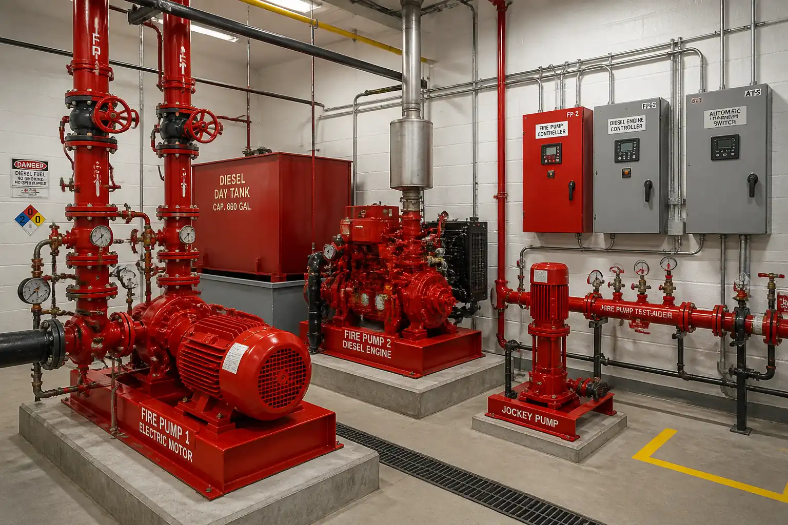
This method covers supply verification, installation, alignment, connection, pre-commissioning, and acceptance testing of a complete fire pump set comprising:
- One electric-driven main fire pump (horizontal split-case or vertical turbine as applicable) [Verify per project specifications]
- One diesel-driven main fire pump
- One jockey (pressure maintenance) pump
- Common fabricated base frames/skids, grout and hold-downs, suction and discharge piping, test header/flowmeter, valves, pressure gauges, controllers, power and control cabling, fuel storage and delivery (diesel), batteries and chargers, exhaust, pump room ventilation, drains, and accessories.
Objectives
- Install and align pumps and drivers to manufacturer tolerances.
- Install suction/discharge piping with correct hydraulics and appurtenances per NFPA 20.
- Complete electrical power and fire pump controller connections with reliable power arrangements [Verify per project specifications and local code].
- Install diesel engine fuel and exhaust systems and provide adequate ventilation/heat rejection.
- Perform hydrostatic tests, pre-commissioning, driver dry-run (uncoupled), and full acceptance flow test to verify performance against certified pump curves.
Exclusions
- Underground fire mains beyond pump room boundary (covered under separate method statement).
- Building fire sprinkler/standpipe distribution beyond pump discharge header (except test header tie-in as required).
References
| Document Type | Reference / Number | Revision | Notes |
|---|---|---|---|
| NFPA 20: Standard for the Installation of Stationary Fire Pumps for Fire Protection (latest edition) | Primary reference for fire pump equipment, layout, piping, controllers, fuel, ventilation, and acceptance testing. | ||
| NFPA 25: Inspection, Testing, and Maintenance of Water-Based Fire Protection Systems | Reference for post-commissioning testing and maintenance expectations. | ||
| NFPA 70 (NEC) or IEC 60364: Electrical Installations | Electrical design, wiring, grounding, and protections [Verify applicable jurisdiction]. | ||
| UL 448 / FM Approved: Centrifugal Fire Pumps; UL/FM Listed Controllers and Accessories | Equipment listing and approvals for fire protection service. | ||
| ASME B31.1/B31.9: Pressure Piping; ASME B16.5: Pipe Flanges and Flanged Fittings | Piping fabrication, flanges, pressure testing [Verify applicable code path with AHJ]. | ||
| Hydraulic Institute Standards (HI) for Pump Installation, Alignment, and Vibration (e.g., HI 9.6.4/9.6.6) | Good practice for alignment tolerances and vibration acceptance. | ||
| ISO 10816/ISO 20816: Mechanical vibration — Evaluation of machine vibration | Vibration limits during test runs [Verify per pump/driver rating]. | ||
| ASTM C1107: Non-shrink Grout | Baseplate grouting material and properties. |
Responsibilities
| Role | Responsibility | Name / Party |
|---|---|---|
| Project Manager | Overall delivery, schedule, interfaces, approvals | Contractor |
| Construction Manager / Site Engineer | Daily supervision, coordination of civil/mechanical/electrical works | Contractor |
| QA/QC Engineer | Quality control, inspections, ITP compliance, records | Contractor |
| HSE Officer | Task-specific risk assessment, permits, toolbox talks, monitoring | Contractor |
| Mechanical Supervisor and Fitters | Mechanical installation, alignment, piping, pressure testing | Contractor |
| Electrical Supervisor and Electricians | Cabling, terminations, grounding, controller/ATS installation | Contractor |
| Instrumentation Technician | Instrumentation, pressure switches/transducers, flowmeter/test header setup | Contractor |
| Commissioning Engineer | Functional testing, start-up, tuning, performance test coordination | Contractor |
| Pump/Controller Vendor Representative | Technical support, alignment tolerances, performance curve, sign-off | Manufacturer |
| Consultant/Engineer/Client Representative | Inspection at hold/witness points, approvals | Employer |
Resources
| Resource Type | Description | Quantity | Remarks |
|---|---|---|---|
| Labor | Lead mechanic, 2–4 fitters, 2 riggers, welder | As required | |
| Labor | 1 supervisor, 2 electricians | As required | |
| Labor | Commissioning engineer, vendor rep, QA/QC | As required |
Materials
| Material | Specification / Grade | Quantity | Remarks |
|---|---|---|---|
| Fire pump (electric-driven) | UL 448/FM Approved; Capacity and head per design [Verify] | ||
| Fire pump (diesel-driven) | UL/FM approved; complete with engine, cooling, exhaust, dual batteries/chargers | ||
| Jockey pump | UL/FM if required; capacity/head per design [Verify] | ||
| Base frames/skids and anchor bolts | Per OEM; anchors per project spec (e.g., ASTM F1554) [Verify] | ||
| Non-shrink grout | ASTM C1107, Class A or C; flowable; shrinkage-compensated | ||
| Suction/discharge piping and fittings | Carbon steel/ductile iron per ASME B31.9; flanges ASME B16.5; coatings [Verify] | ||
| Valves (OS&Y/BF indicating, check, relief) | UL/FM listed; pressure class per design [Verify] | ||
| Instruments and accessories | Gauges 0–300 psi typical [Verify]; pressure switches/transducers UL/FM | ||
| Fire pump controllers and ATS | UL/FM listed; features per NFPA 20 and project spec | ||
| Diesel day tank and fuel piping | UL-142 or equivalent; capacity for ≥8 hours operation [Verify] | ||
| Starting batteries and chargers (diesel) | Per OEM; UL listed; separate chargers on dedicated AC feeds |
Equipment
| Equipment | Capacity / Type | Quantity | Inspection Required |
|---|---|---|---|
| Mobile crane/forklift and rigging gear | Rated for heaviest component +25% [Verify] | Lifting gear inspected and certified | |
| Laser/dial indicators for alignment | Resolution ≤0.01 mm | Calibration certificates valid | |
| Torque wrenches | Cover all OEM torque ranges | Calibration certificates valid | |
| Hydrostatic test pump and calibrated gauges | Up to test pressure +10% | Gauges calibrated per ISO 17025 | |
| Electrical test instruments (megger, clamp meter, phase rotation) | Megger 500–1000 V | Calibration certificates valid | |
| Tachometer and vibration meter | RPM range per engine/motor; vibration ISO 10816 | Calibration certificates valid | |
| Pitot gauges/flowmeter and test header equipment | Per system flow [Verify] | Calibration certificates valid |
Prerequisites
- Approved IFC drawings, equipment submittals (UL/FM certificates, pump curves), method statement, risk assessment, and ITP.
- Room readiness: Finished foundations with verified elevations/flatness (≤2 mm in 1000 mm), embedded inserts/anchor locations checked.
- Power availability: Dedicated fire pump feeder(s)/ATS arrangement approved by AHJ [Verify per project and local code].
- Water source availability: Suction tank/underground main charged; test header discharge route established with permits for water disposal [Verify].
- Permits: Hot work, electrical work, lifting plan, confined space (if applicable) [Verify per project HSE plan and local regulations].
- Calibrated instruments available; vendor representative booking confirmed for alignment and testing.
- Ventilation and fuel system design/calculations approved (diesel engine heat rejection and intake/exhaust sizing) [Verify].
- Spare parts, consumables, and safety signage available.
Method Sequence
| Step | Activity | Description | Responsibility | Inspection / Hold Point |
|---|---|---|---|---|
| 1 | Receipt and inspection of equipment | Inspect pumps, controllers, ATS, tanks, accessories for damage, completeness, and certifications; verify nameplate data vs. submittals. | QA/QC + Storekeeper | Visual; document check |
| 2 | Foundation check and layout | Confirm foundation dimensions, level, anchor bolt positions; mark base frame footprint and grout pads. | Site Engineer | Survey |
| 3 | Set base frame and preliminary leveling | Place base frame on steel shims/leveling screws; level in two axes; snug anchors. | Mechanical Supervisor | Level check |
| 4 | Base grouting | Form and pour flowable non-shrink grout under base; vibrate externally; cure as per ASTM C1107 and OEM. | Mechanical Supervisor | Grout batch and pour |
| 5 | Place pumps/drivers and rough align (uncoupled) | Mount pumps and motors/engines; correct soft foot; align using laser/dials with coupling removed or uncoupled. | Mechanical Supervisor + Vendor Rep | Dimensional check |
| 6 | Suction piping installation | Install straight suction approach length 5–10 pipe diameters minimum upstream; fit eccentric reducer flat on top; avoid high points; provide OS&Y/BF indicating valve and suction pressure gauge; install air release if per NFPA 20; ensure no strain on pump nozzle. | Mechanical Supervisor | Fit-up, flange alignment |
| 7 | Discharge piping and appurtenances | Install discharge check valve followed by OS&Y/BF valve; fit pressure relief valve if required; casing relief valve and pressure gauge; minimum-flow bypass if specified; connect flowmeter or test header with hose valves to safe discharge. | Mechanical Supervisor | Layout and supports |
| 8 | Pipe supports and hydrostatic test | Install supports/springs; isolate equipment; hydrotest per code/project spec. | Mechanical Supervisor + QA/QC | Test setup and hold |
| 9 | Electrical installation | Install fire pump controllers and ATS; run dedicated feeders; terminate power/control; ground per code; interlock supervisory signals to fire alarm as required; verify phase rotation. | Electrical Supervisor | Cabling and terminations |
| 10 | Diesel fuel system and exhaust | Install double-wall day tank with bund (≥110% capacity); fill/return/vent/overflow lines; leak detection; flexible fuel hoses; exhaust with flex connector, silencer, lagging; condensate drain; routing to outdoor safe point; cooling/heat exchanger piping per OEM. | Mechanical Supervisor | Tank and piping |
| 11 | Ventilation and room services | Install intake/exhaust louvers/fans per calc; ensure make-up air; temperature control to remain within engine/motor OEM limits; provide floor drains/sumps and lighting; ensure clearances around equipment (≥1 m typical) [Verify]. | MEP Supervisor | Airflow/area check |
| 12 | Final alignment and coupling | After grout cure and piping completion, recheck alignment; correct to tolerance; install and secure coupling and guard; torque verify. | Mechanical Supervisor + Vendor Rep | Alignment verification |
| 13 | Flushing and cleaning | Flush suction/discharge lines at high velocity; remove debris; remove temporary strainers after flush; clean strainers where provided. | Mechanical Supervisor | Flushing setup |
| 14 | Pre-functional checks | Verify lube oil, coolant (diesel), coupling guard fitted, gauges installed/calibrated, valve positions set (suction open, discharge closed for start-up as per OEM), controller settings (auto/manual/start), battery voltage/charger outputs, alarms. | Commissioning Engineer | Checklist |
| 15 | Driver dry-run (uncoupled) | Run electric motor and diesel engine separately with coupling disengaged to confirm rotation, electrical integrity, and engine stability; duration per OEM; monitor vibration and noise. | Commissioning Engineer + Vendor Rep | On-site |
| 16 | Wet run and operational checks (coupled) | Prime pump; open discharge partially; start in manual; verify pressures, leaks, controller indications; set pressure switch settings; verify automatic weekly test as applicable. | Commissioning Engineer | Operational |
| 17 | Acceptance flow test | Conduct test via flowmeter or test header using calibrated pitot gauges; record suction/discharge pressures and flows at churn (0%), 100%, and 150% of rated flow; capture motor current/voltage or diesel RPM/fuel; calculate net pressures. | Commissioning Engineer + Third Party + Vendor Rep | Performance test |
| 18 | Final settings and handover | Set controllers to AUTO; restore normal valve positions; label equipment; provide training; submit as-builts, O&Ms, test certificates; implement weekly test schedule. | Project Manager + Commissioning Engineer | Documentation |
Safety Controls
Task-Specific Hazard Controls
- Hazard: Heavy lifting of pumps, engines, skids
- Likely consequence: Crush injuries, dropped loads, equipment damage
- Engineering/procedural control: Appointed person lift plan; rated crane/forklift; certified slings/shackles; taglines; exclusion zone; pre-lift meeting
- Required PPE: Helmets, safety boots, gloves, high-vis, eye protection
- Collective preventive measure: Barriers and banksman control; load path isolation
-
Inspection/permit/supervision: Lifting gear certificates; daily crane checks; Lift permit; competent rigger/banksman
-
Hazard: Electrical energization during testing
- Likely consequence: Electrocution, arc flash
- Engineering/procedural control: Lockout/tagout; insulated tools; correct phase rotation checks with tester; arc-flash boundaries; dedicated fire pump feeders per code
- Required PPE: Arc-rated clothing [Verify], insulated gloves, face shield
- Collective preventive measure: Barriers and signage; restricted access during energization
-
Inspection/permit/supervision: Electrical work permit; competent electrician; IR test records
-
Hazard: Pressure testing and live pressurized systems
- Likely consequence: Hose whip, sudden release, injury
- Engineering/procedural control: Rated hoses/fittings; gradual pressurization; exclusion zone; pressure relief provision; secure gauges
- Required PPE: Eye protection, gloves, boots
- Collective preventive measure: Barriers and remote monitoring where possible
-
Inspection/permit/supervision: Hydrotest procedure approval; calibrated gauges; supervisor present
-
Hazard: Rotating machinery during dry-run and wet-run
- Likely consequence: Entanglement, impact
- Engineering/procedural control: Fit guards before coupled runs; keep loose clothing away; no access to rotating parts; use remote start/stop
- Required PPE: Eye protection, gloves, hearing protection
- Collective preventive measure: Physical guarding and interlocks where provided
-
Inspection/permit/supervision: Start-up checklist; supervision by commissioning lead and vendor rep
-
Hazard: Diesel fuel handling and exhaust gases
- Likely consequence: Fire, explosion, inhalation of CO/NOx, burns
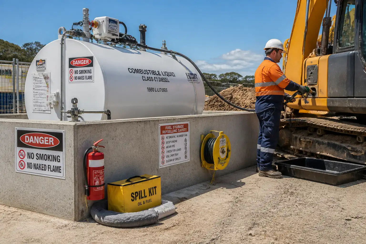
- Engineering/procedural control: Double-wall/bunded tank; grounded transfers; no smoking; intrinsically safe detectors; proper exhaust routing with lagging; ventilation operational before engine start
- Required PPE: Anti-static clothing, gloves, goggles
- Collective preventive measure: Spill kits and fire extinguishers (foam/CO2) staged; emergency shutoffs
-
Inspection/permit/supervision: Hot work permit for exhaust welding; fuel system pressure/leak tests; CO detector calibration
-
Hazard: Hot works for piping/exhaust
- Likely consequence: Fire, burns, fumes
- Engineering/procedural control: Hot work permits; fire watch; remove combustibles; welding screens; ventilation
- Required PPE: Welding helmet, fire-resistant gloves/clothing, respirator if required
- Collective preventive measure: Fire blankets, extinguishers; designated hot work area
-
Inspection/permit/supervision: WPS/PQR; welder qualifications; gas leak checks
-
Hazard: Confined/poorly ventilated pump room
- Likely consequence: Asphyxiation, heat stress
- Engineering/procedural control: Verify ventilation and temperature limits; heat stress management; monitor oxygen if required
- Required PPE: Hearing protection, hydration plan
- Collective preventive measure: Mechanical ventilation; temperature monitoring
-
Inspection/permit/supervision: Confined space permit if criteria met [Verify per project HSE plan and local regulations]
-
Hazard: Chemical exposure to grout and oils
- Likely consequence: Skin/eye irritation
- Engineering/procedural control: SDS briefing; wet-work controls; hygiene facilities
- Required PPE: Chemical-resistant gloves, goggles, long sleeves
- Collective preventive measure: Spill containment; eyewash availability
-
Inspection/permit/supervision: SDS on site; COSHH-style assessment [Verify]
-
Hazard: Noise during engine/pump testing
- Likely consequence: Hearing damage
- Engineering/procedural control: Limit exposure time; install silencers; keep doors closed if designed for
- Required PPE: Ear defenders
- Collective preventive measure: Noise barriers/signage
- Inspection/permit/supervision: Noise survey if required
[Verify per project HSE plan and local regulations] applies to all permits and statutory requirements.
Environmental Controls
- Water discharge from flow testing
- Impact: Flooding, erosion, siltation
-
Control: Route to approved drain or temporary discharge line with energy dissipation; use silt socks; obtain discharge permit if required; monitor chlorine if from potable source [Verify]
-
Diesel fuel spills/leaks
- Impact: Soil and water contamination
-
Control: Double-wall/bunded tanks (≥110% capacity); drip trays; spill kits; trained responders; proper labeling; periodic integrity checks
-
Exhaust emissions and noise
- Impact: Air pollution, nuisance
-
Control: Maintain engine; fit silencer; schedule tests during permitted hours; keep doors/windows per acoustic design
-
Waste management
- Impact: Landfill burden, contamination
-
Control: Segregate metal, cardboard, plastic; dispose of oily rags/filters as hazardous; return pallets to supplier; grout waste cured before disposal
-
Energy use
- Impact: Unnecessary consumption
-
Control: Switch off non-essential equipment; minimize idling; efficient testing regime
-
Documentation
- Control: Maintain environmental logs, permits, and waste transfer notes.
QA/QC
Quality Controls
- Submittals: Approvals for pumps, controllers, ATS, valves, gauges, tanks, cables, grout, paints, ventilation, and certified pump curves.
- Calibration: All pressure gauges, flowmeters, electrical meters, tachometers, and vibration meters to have valid ISO 17025 traceable calibration.
- Welding: WPS/PQR approved; welder qualifications current; visual and NDT per project [Verify].
- Materials: UL/FM listings verified; nameplates recorded; compliance with NFPA 20.
- Alignment: Records at initial and final stages; tolerances per OEM/HI standards.
- Piping: Fit-up and hydrotest certificates; paint/coat DFT reports if applicable.
- Electrical: IR and continuity test records; torque logs; grounding test results.
- Fuel/Exhaust: Leak/backpressure records; ventilation commissioning sheet.
- Hold/Witness Points: As identified in Method Sequence and ITP (foundation check, base grouting, final alignment, hydrotest, pre-energization, driver dry-run, acceptance flow test, performance curve verification).
- Documentation: As-built drawings; O&M manuals; training attendance; spare parts list; warranty certificates.
Acceptance
- System achieves performance at churn, 100%, and 150% points within NFPA 20 tolerances and matches certified pump curves within acceptable variance [Verify per AHJ].
- All safety devices, alarms, indicators, and controllers operate correctly in AUTO and manual modes.
- No leaks; vibration, temperature, and electrical readings within OEM/HI/ISO limits.
Attachments
- Approved IFC drawings (pump room layout, piping, electrical SLD)
- Vendor certified pump curves and datasheets (electric, diesel, jockey)
- UL/FM certificates (pumps, controllers, valves, accessories)
- Base frame and grout details; grout data sheets and MSDS
- Lifting plan and rigging certificates
- WPS/PQR and welder qualifications (if welding performed)
- Electrical test reports (IR, continuity, torque) and grounding test
- Hydrostatic test certificates and flushing records
- Ventilation calculations and commissioning sheet
- Fuel system leak test and exhaust backpressure records
- Alignment records (initial and final)
- Driver dry-run report
- Acceptance performance test report with curve overlay and instrument calibration certificates
- O&M manuals, as-built drawings, training records, warranties
This content is a read-only public reference. Download or customize to get an editable version.
ITP preview
The first inspection activities from the linked ITP for Method Statement: Installation and Commissioning of Electric/Diesel Fire Pump and Jockey Pump System:
| Activity | Inspection / Test | Acceptance Criteria | Responsibility | Record |
|---|---|---|---|---|
| Material receipt and verification | Certificates, UL/FM listings, curves | Conformity to approved submittals; no damage | QA/QC Engineer | MIR; Certificates; Photos |
| Foundation level and anchors inspection (Hold) | Survey level/position | Flatness ≤2 mm/1 m; anchors within tolerance | Site Engineer + QA/QC + Consultant | Survey Report; ITP Checklist |
| Base frame setting and pre-grout inspection (Hold) | Level check; shim locations | Levelness ≤0.2 mm/m; grout gap 25–50 mm | QA/QC + Consultant | Pre-Grout Inspection |
Showing 3 of 12 inspection activities. View full ITP →
Related Inspection and Test Plan
An Inspection and Test Plan (ITP) is available for Method Statement: Installation and Commissioning of Electric/Diesel Fire Pump and Jockey Pump System. The ITP defines the inspection activities, acceptance criteria, hold and witness points, responsible parties, and records required to verify the work described in this method statement.
View the Method Statement: Installation and Commissioning of Electric/Diesel Fire Pump and Jockey Pump System ITP →Frequently asked questions
Continue with related Quollnet resources connected to this method statement.