
Method Statement – Installation of Large-Format Mirrored Wall Panels in Commercial Gymnasium Dance Studios – Method Statement
AI-assisted method statement with matching ITP, PDF download, and Excel export.
More than a static template
Unlike a downloadable Word or PDF template, this method statement is an AI-assisted editable starting point connected directly to a matching Inspection and Test Plan. Every section is structured, project-adaptable, and ready to export.
- AI-assisted drafting — Customize every section with AI for your specific project scope.
- Linked ITP — A matching inspection and test plan is generated alongside the method statement.
- Multiple export formats — Download as a formatted PDF or editable Excel spreadsheet.
- Editable starting point, not a final document — Review, verify, and adjust all content against your project requirements before use.
Static template vs. Quollnet workflow
| Feature | Static template | Quollnet |
|---|---|---|
| Project-specific content | Manual fill-in required | AI-assisted customization |
| Linked ITP | Separate document, no link | Matching ITP included |
| Export formats | Usually PDF only | PDF and Excel |
| Structured sections | Free-form layout | 13 standardized sections |
| Saved to your account | Local file only | Cloud-saved, reusable |
| Content accuracy | You verify everything | AI-assisted, you still verify |
| Cost | Often free but time-intensive | Free to customize and download |
What you can customize
When you save this method statement to your account, every section becomes editable. The following 13 sections are included:
- Scope — Defines the activity and its boundaries.
- References — Standards, specifications, and drawings.
- Responsibilities — Roles and accountabilities.
- Resources — Labour, plant, and equipment summary.
- Materials — Materials and compliance requirements.
- Equipment — Tools and equipment details.
- Prerequisites — Hold points and pre-conditions.
- Method sequence — Step-by-step construction sequence.
- Safety controls — HSE risk controls and PPE.
- Environmental controls — Environmental mitigation measures.
- QA/QC — Quality inspection and test requirements.
- ITP — Inspection and Test Plan table (has its own page).
- Attachments — Referenced drawings and documentation.
Why this method statement is used
This method statement is used to define and communicate the approved procedure for carrying out method statement – installation of large-format mirrored wall panels in commercial gymnasium dance studios on site. It ensures the work is planned in advance, the correct resources and controls are in place, and all personnel understand responsibilities, sequence, quality requirements, and safety controls before work begins. It aligns site execution with the documented scope and acceptance expectations.
Who uses this method statement
This method statement is used by contractors, site supervisors, project engineers, QA/QC engineers, HSE officers, consultants, and client representatives. It serves as a shared reference for planning, execution, supervision, inspection, and approval of the activity on site.
When it is prepared and submitted
The method statement is prepared before the work activity starts and submitted as part of the pre-construction documentation package for review and approval.
Who reviews or approves it
The method statement is usually submitted to the client representative, consultant, resident engineer, or project management consultant for review and approval before the work commences.
Important approval note
This method statement is an AI-assisted editable starting point, not a pre-approved document. Before use on any project, all content must be reviewed and approved by the relevant parties (superintendent, principal contractor, or client representative) in accordance with your contract and project quality plan.
For example: if your specification requires a departure from a referenced standard, that departure must be documented and approved separately — this method statement will not capture that automatically. Always verify against your applicable drawings, specifications, and regulatory requirements.
Method statement content
Scope
Overview
This method statement covers the complete installation of large-format mirrored wall panels in commercial gymnasium dance studios, including:
- Substrate (gypsum board/drywall) inspection, sanding/skim coating for flatness, dust control, and priming/sealing.
- Survey, layout, and mechanical fixing of bottom support J-channels/edge trims, including setting blocks and soft liners.
- Safety-shatter backing film application to mirror panels (where not factory laminated), edge finishing/arris, and inspection.
- Specialized mirror-approved mastic adhesive comb application to the substrate and/or mirror back as per adhesive manufacturer, with defined coverage and thickness tolerances.
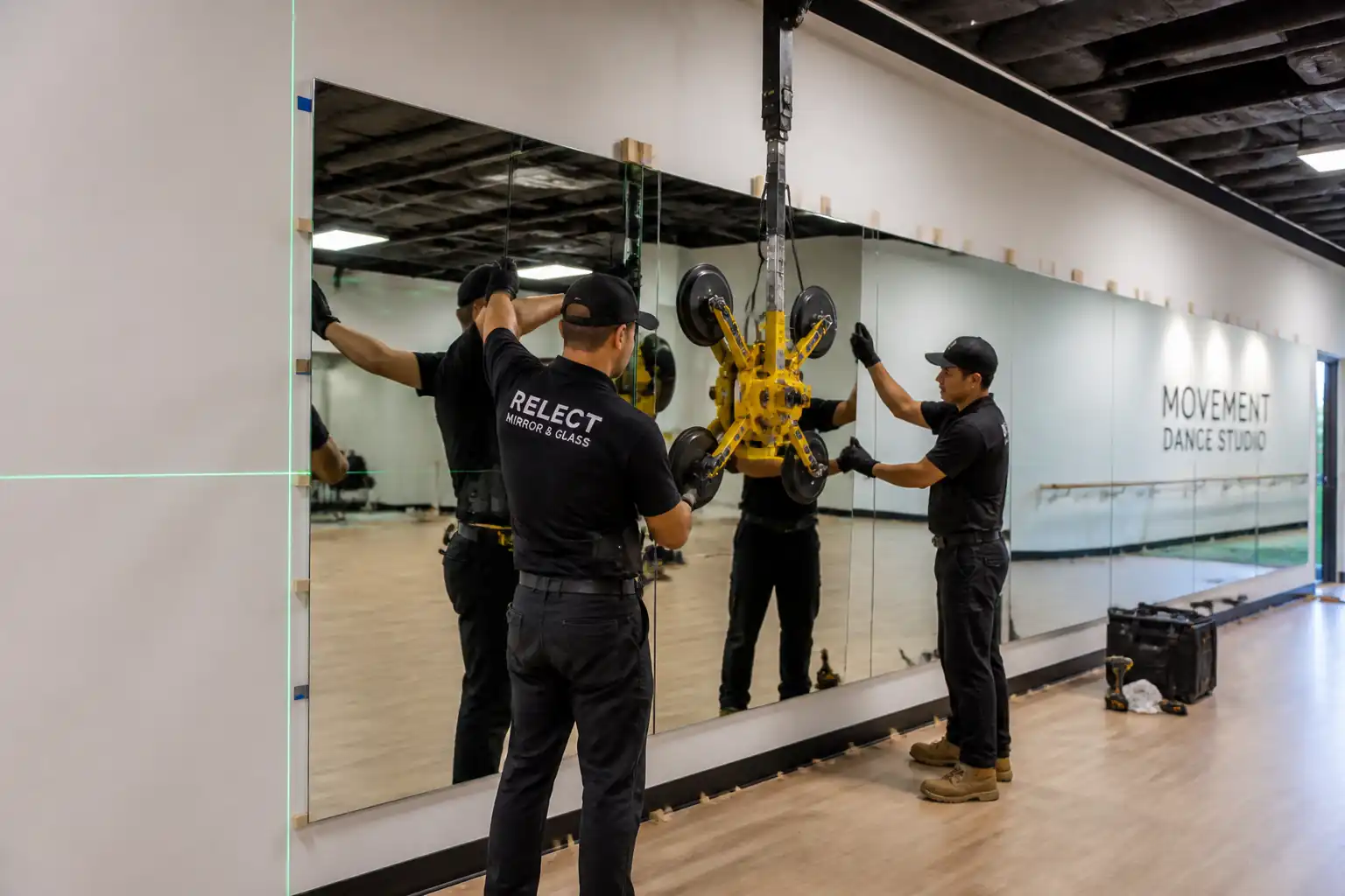
- Controlled lifting/placement of large-format mirrors, spacer-based joint management, and alignment to achieve distortion-free reflection.
- Perimeter/joint sealant application (mirror-safe neutral cure), cleaning, protection, and cure time management.
- Integrated QA/QC checks, ITP hold/witness points, and safety sign-off logs for handover.
Inclusions
- Wall surveys, flatness and plumb checks, and moisture/environmental condition verification.
- Fixings into studs or engineered backing per approved shop drawings.
- Optical quality checks per BS EN 1036 visual inspection guidance.
- Safety records, daily equipment checks (vacuum lifters), and final documentation.
Exclusions
- Structural wall framing alterations beyond minor backing verification.
- Electrical or AV relocations concealment works (unless stated in contract).
- Supply/installation of dance barres or other fixtures (unless noted in drawings).
Typical Extents [Verify per project specifications]
- Mirror thickness: 6 mm silvered float mirror (tempered if required by risk assessment or local code).
- Panel sizes: up to approx. 3.0 m high x 1.2–1.8 m wide.
- Joint gap targets: 2–3 mm uniform.
- Substrate flatness targets: ≤ 2 mm under a 2 m straightedge; ≤ 3 mm under 3 m.
References
| Document Type | Reference / Number | Revision | Notes |
|---|---|---|---|
| Standard | BS EN 1036-1/-2: Glass in building — Mirrors from silver-coated float glass | Optical/visual quality, dimensional tolerances, and evaluation methods for silvered mirrors. | |
| Standard | BS 6262 (series): Glazing for buildings | General glazing practice and safety guidance. [Verify applicable parts per project] | |
| Standard | EN 12150-1: Thermally toughened soda lime silicate safety glass | If toughened safety mirrors are specified or required by code/risk assessment. | |
| Standard | EN 12600: Glass in building — Pendulum test — Impact performance classification | Safety classification for glazed elements and films; target Class 2B2 for internal mirrors [Verify]. | |
| Standard | ANSI Z97.1 / CPSC 16 CFR 1201 | US safety glazing standards if jurisdiction requires compliance. [Verify per local code] | |
| Standard | ASTM C1036: Standard Specification for Flat Glass | Base flat glass quality reference for float substrate mirrors. | |
| Standard | ASTM C1048: Heat-Treated Flat Glass | If heat-strengthened/toughened mirror glass is used or required. | |
| Standard | ASTM C840 / GA-214: Application and Finishing of Gypsum Board | Drywall finishing levels and substrate tolerances for flatness/wave control. | |
| Guideline | Adhesive and Sealant Manufacturers’ TDS/SDS (Mirror-Safe) | Adhesive compatibility with mirror silvering; application thickness, coverage, curing times. | |
| HSE | Project HSE Plan; Local Regulations; Permit-to-Work System | Working at height, manual handling, drilling/hidden services scans, VOCs, dust, glass handling. [Verify per project HSE plan and local regulations] |
Responsibilities
| Role | Responsibility | Name / Party |
|---|---|---|
| Project Manager | Ensure compliance with contract documents, standards, and HSE. | Main Contractor |
| Site Engineer / Supervisor | Maintain red-line drawings, RFI management, and as-builts. | Main Contractor |
| Glazing Subcontractor Lead | Provide qualified glaziers; tools and lift plans; equipment inspections. | Specialist Subcontractor |
| Drywall Finisher | Deliver substrate to tolerance and cleanliness. | Main/Subcontractor |
| QA/QC Engineer | Issue NCRs, close-out punch list, maintain records. | Main Contractor |
| HSE Officer | Verify PPE, equipment certifications, and exclusion zones. | Main Contractor |
| Surveyor / Setting-Out Engineer | Provide survey reports and benchmarks. | Main Contractor |
| Storekeeper | Check deliveries against approvals; keep SDS on site. | Main Contractor |
| Third-Party Inspector (if applicable) | Issue reports and witness statements. | Independent |
Resources
| Resource Type | Description | Quantity | Remarks |
|---|---|---|---|
| Manpower | Glaziers (certified) | 3–6 per crew [Verify per panel size/weight] | Vacuum-lifter competent persons only. |
| Manpower | Drywall finisher(s) | 1–3 | Level 4+ finish capability (GA-214). |
| Manpower | Site supervisor / engineer | 1 | |
| Manpower | HSE officer | 1 (shared) | Critical lift oversight as needed. |
| Manpower | QA/QC engineer | 1 (shared) | ITP implementation and records. |
Materials
| Material | Specification / Grade | Quantity | Remarks |
|---|---|---|---|
| Silvered float mirror panels | BS EN 1036 compliant; base float per EN 572; toughened per EN 12150 where required [Verify] | Factory polished edges preferred. | |
| Safety-shatter backing film | Meets EN 12600 Class 2B2 or ANSI Z97.1 Cat II when applied [Verify] | Back film sized to mirror; trimmed near edges. | |
| Mirror mastic adhesive (comb/trowel grade) | Manufacturer-certified mirror-compatible adhesive; application by 4–6 mm V-notched trowel [Verify per TDS] | TDS to confirm compatibility with mirror silvering. | |
| Perimeter/joint sealant (mirror-safe) | Neutral cure silicone or approved mirror-safe sealant [Verify per TDS] | Colour matched; tooling within open time. | |
| Aluminium J-channel and trims | Alloy and finish per specification; wall fixings SS A2/A4 [Verify] | Powder-coated/clear anodized. | |
| Setting blocks / soft liners (EPDM/neoprene) | Shore A ~70, solvent-resistant [Verify] | ||
| Hard spacers/shims (2–3 mm) | Plastic/Nylon; compressible <10% at load [Verify] | ||
| Primer/sealer for gypsum board | Acrylic/PVA compatible with mirror adhesive [Verify per TDS] | ||
| Cleaning and protection materials | pH-neutral glass cleaner; protection sheets/tape |
Equipment
| Equipment | Capacity / Type | Quantity | Inspection Required |
|---|---|---|---|
| Vacuum glass lifter (suction frame) | ≥ 2x panel weight safety factor [Verify] | Yes | |
| A-frame glass racks and dollies | Rated for panel load | Yes | |
| Rotary laser level, targets, and 2 m straightedge | Calibration cert current | ||
| Stud/pipe/AC cable detector (multi-scanner) | Functional check | ||
| Drills, drivers, countersink with dust extraction | PAT/inspection current | ||
| Mobile scaffold/step-ups or MEWP (indoor) | As required by height | Tagged/inspected | |
| V-notched trowels (4–6 mm), sealant guns | Clean, undamaged | ||
| Squeegees, mist sprayers, lint-free wipes, HEPA vac | Cleanliness prior to use | ||
| Diamond hand pads/glass edge tools | Use guards; check condition | ||
| Thermo-hygrometer and surface moisture meter | Calibration/zero check |
Prerequisites
Approvals and Documentation
- Approved shop drawings, layout elevations, details of J-channel/backing, jointing, and sealant.
- Approved material submittals: mirrors, safety film, adhesive, sealant, trims, setting blocks, primers (include TDS/SDS).
- Method statement and ITP approved before start.
Training and Permits
- Toolbox talk on glass handling, vacuum lifting, pinch/crush hazards, and drilling controls.
- Permit-to-work for drilling/penetrations and work at height [Verify per project HSE plan and local regulations].
- Equipment certifications (vacuum lifter, scaffold/MEWP) current and logged.
Site Readiness
- Substrate complete, services behind wall verified and marked (multi-scanner/GPR where needed) with as-built confirmation.
- Environmental conditions: temperature 18–27°C; RH 30–65%; ventilation in place. [Verify per adhesive TDS].
- Substrate dryness: gypsum board dry with moisture meter reading within device “drywall” safe range; no visible dampness [Record value, Verify per device manual].
- Illumination 300–500 lux minimum for visual/optical checks.
- Access routes clear; A-frame storage area level and protected from traffic; exclusion zones established.
Mock-up
- Execute one full-height mirror bay mock-up (≥2 panels where feasible) demonstrating J-channel, adhesive comb, joint, sealant, and final finish for acceptance prior to full works. Retain as quality benchmark.
Materials Handling
- Inspect mirrors on delivery for chips/scratches; store vertically on A-frames at 6–10° lean with edge protectors; segregate by size and ID tags.
- Condition adhesives/sealants to room temperature 24 hours prior to use.
Coordination
- Confirm sequencing with flooring/baseboard trades and any barre/AV fixtures to avoid rework. Lock-in joint lines with architectural grid/lighting for reflection alignment.
Method Sequence
| Step | Activity | Description | Responsibility | Inspection / Hold Point |
|---|---|---|---|---|
| 1 | Setting-out and Wall Survey | Establish control lines with laser; mark mirror datum at finished floor level (FFL). Check plumb and level of walls; mark stud/backing locations. Record flatness using 2 m straightedge in orthogonal directions; note high/low spots. | Site Engineer / Surveyor | Yes |
| 2 | Drywall Preparation | Sand/skim low/high areas to achieve target flatness; repair joints/fasteners. HEPA vacuum to remove dust. Apply compatible primer/sealer; allow to dry per TDS. | Drywall Finisher | Yes |
| 3 | Services Scan and Permit | Scan wall with multi-scanner to locate studs, electrical/pipe services. Mark no-drill zones. Obtain permit-to-drill as applicable. | Site Engineer / HSE | Yes |
| 4 | Install J-Channel and Trims | Cut and dry-fit J-channel; install soft liner. Fix into studs/backing with SS screws. Maintain level using laser. Install setting blocks in channel at 300–500 mm spacing. | Glazing Subcontractor | Yes |
| 5 | Mirror Edge Preparation | Verify factory polished edges. Where permitted, lightly arris micro-chips with diamond hand pad (≤1 mm arris). Clean edges with approved solvent (no ammonia). | Glazing Subcontractor | Yes |
| 6 | Safety Backing Film Application (if required) | On clean bench, mist-clean mirror back; apply film wet per TDS; squeegee out air/water from center to edges. Trim film to within ~2 mm of glass edge [Verify]. Allow initial cure per TDS (≥24 h) before lift. | Glazing Subcontractor | Yes |
| 7 | Dry-Fit and Alignment Trial | Position panel without adhesive using J-channel and spacers; verify joint gaps (2–3 mm) and alignment with adjacent panels/room grid. Mark top alignment points. | Glazing Subcontractor | Yes |
| 8 | Adhesive Comb Application | Mask perimeters. Apply mirror-approved mastic to primed substrate using 4–6 mm V-notched trowel in vertical ribbons; maintain 10–20 mm clear from mirror edges. Ensure final bed thickness ~1.5–2.5 mm and 70–85% contact after placement. | Glazing Subcontractor | Yes |
| 9 | Panel Lifting and Placement | Pre-use check of vacuum lifter; attach to mirror (face protected). Lift panel, lower into J-channel on setting blocks; use spacers at vertical joints/top. Press uniformly to seat adhesive without over-compression. Temporary retention with tape/clips as required. | Glazing Subcontractor | Yes |
| 10 | Alignment and Distortion Check | Verify plumb/level with laser. Conduct reflection check using vertical/horizontal grid or plumb lines at 1 m viewing distance at 90°. Adjust before adhesive set within open time. | QA/QC + Glazing Subcontractor | Yes |
| 11 | Curing and Supports | Maintain temporary supports/tape. Protect area from impact/vibration. Observe adhesive cure time (min 24 h; full cure 48–72 h) and temperature/RH per TDS. | Glazing Subcontractor | Yes |
| 12 | Joint and Perimeter Sealing | Remove spacers; mask edges. Apply neutral-cure mirror-safe sealant to 2–3 mm joints; tool smooth; remove masks after skinning. | Glazing Subcontractor | Yes |
| 13 | Cleaning and Protection | Remove surface films/tapes carefully. Clean face with pH-neutral, non-ammonia cleaner and lint-free cloth. Install protective barriers/signs to prevent early use. | Glazing Subcontractor | Yes |
| 14 | Handover and Records | Complete ITP, snag rectification, and safety glazing compliance log. Provide O&M manuals, cleaning/maintenance guidance, warranties, and as-built drawings/photos. | Project Manager / QA/QC | Yes |
Health, Safety, and Environment – Safety Controls
Principal Task-Specific Hazards and Controls
- Hazard: Handling large glass panels; loss of control or breakage
- Consequence: Severe cuts/lacerations, crush injuries, panel shatter
- Engineering/Procedural Control: Use certified vacuum lifters with pre-use checks; plan lift path and exclusion zones; minimum two trained glaziers per panel side; use A-frames and edge protectors; install temporary barriers
- Required PPE: Cut-resistant gloves (EN 388 level appropriate), forearm guards, safety footwear with toe protection, long sleeves, eye/face protection
- Collective Preventive Measure: Physical barriers and spotters; dedicated lifting plan; limit occupancy in zone
-
Inspection/Permit/Supervision: Daily vacuum lifter inspection log; lifting plan briefing; supervisor present during lifts
-
Hazard: Drilling into walls (J-channel fixings) with concealed services
- Consequence: Electric shock, flooding, service damage
- Engineering/Procedural Control: Multi-scanner/GPR prior to drilling; mark no-go zones; lock-out/tag-out if needed; use depth stops
- Required PPE: Safety glasses, dielectric gloves as appropriate, hearing protection
- Collective Preventive Measure: Permit-to-drill system; supervision during first-of-type
-
Inspection/Permit/Supervision: Permit-to-work; inspection of scans and sign-off by engineer/HSE
-
Hazard: Work at height (top alignments/sealant)
- Consequence: Falls from height
- Engineering/Procedural Control: Use inspected mobile scaffold or MEWP; 3-point contact; do not overreach; maintain guardrails/toeboards
- Required PPE: Fall protection per equipment SOP, non-slip footwear
- Collective Preventive Measure: Edge protection on platforms; exclusion below
-
Inspection/Permit/Supervision: Daily scaffold tag/MEWP checks; operator certification verification
-
Hazard: Adhesive/sealant VOCs and skin contact
- Consequence: Respiratory/skin irritation, sensitization
- Engineering/Procedural Control: Select low-VOC, mirror-safe products; provide cross-ventilation; avoid skin contact; follow SDS for handling and cure
- Required PPE: Nitrile gloves, safety glasses; respirators if indicated by SDS
- Collective Preventive Measure: Local ventilation; restrict area occupancy until initial cure
-
Inspection/Permit/Supervision: SDS available; HSE to verify ventilation plan [Verify per project HSE plan and local regulations]
-
Hazard: Drywall sanding dust and silica-containing residues
- Consequence: Respiratory irritation
- Engineering/Procedural Control: Use HEPA vac-attached sanders; wet wipe; contain area
- Required PPE: FFP2/FFP3 or N95 respirator (as required), safety glasses
- Collective Preventive Measure: Dust curtains/negative air if needed
-
Inspection/Permit/Supervision: HSE inspection of controls; housekeeping checks
-
Hazard: Pinch/crush between mirror and wall/channel during seating
- Consequence: Finger/hand injuries
- Engineering/Procedural Control: Use spacers; designated hand positions; verbal commands by lift lead
- Required PPE: Cut-resistant gloves; knuckle protection
- Collective Preventive Measure: Exclusion of non-essential personnel
-
Inspection/Permit/Supervision: Supervisor oversight during placement
-
Hazard: Noise/vibration from drilling and cutting
- Consequence: Hearing damage; nuisance to occupants
- Engineering/Procedural Control: Use low-noise drill modes, maintain bits; schedule noisy tasks off-hours
- Required PPE: Hearing protection as needed
- Collective Preventive Measure: Signage and barriers
-
Inspection/Permit/Supervision: HSE monitoring; compliant hours of work
-
Hazard: Glass edge finishing (hand diamond pads)
- Consequence: Flying shards/abrasion
- Engineering/Procedural Control: Perform only minor arris; use guards and bench with restraints; capture debris
- Required PPE: Face shield or safety glasses, cut-resistant gloves
- Collective Preventive Measure: Screen off workbench area
-
Inspection/Permit/Supervision: Supervisor authorization for any on-site edge work
-
Hazard: Housekeeping and trip hazards (spacers, offcuts, tapes)
- Consequence: Slips, trips, falls
- Engineering/Procedural Control: Clean-as-you-go; tool lanyards at height
- Required PPE: Safety footwear
- Collective Preventive Measure: Waste bins at point of use
- Inspection/Permit/Supervision: Daily HSE walkdown
Note: Where exact controls depend on local law or the project HSE plan, implement and verify: [Verify per project HSE plan and local regulations].
Environmental Controls
- VOC Management: Select low-VOC adhesives/sealants; maintain ventilation during and after application until initial cure. Keep containers closed when not in use.
- Dust Control: Use HEPA-extracted sanding; vacuum surfaces; avoid dry sweeping. Bag and seal dust waste.
- Waste Segregation: Segregate glass offcuts, film liners, cardboard, and plastics. Recycle where facilities exist. Dispose of adhesive/sealant waste and contaminated wipes per SDS.
- Noise: Schedule drilling during permitted hours; use quieter tools and maintain bits to reduce noise.
- Spill Prevention: Store adhesives/sealants on drip trays; keep spill kits nearby; clean spills immediately with approved materials.
- Energy/Lighting: Use LED task lights; switch off equipment when idle.
- Transport/Storage: Store mirrors indoors on level A-frames with edge protectors to prevent damage (waste). Protect from temperature extremes and moisture.
- Nuisance Containment: Screen off work area to prevent dust migration to gym spaces; maintain good housekeeping.
- Compliance: Follow ISO 14001-aligned project environmental plan and local waste regulations. [Verify per project specifications].
Quality Assurance and Quality Control
Controls and Measurements
- Substrate Flatness/Plumb: Check every 2 m along wall with 2 m straightedge; record maximum deviation. Re-check after skim/prime.
- Environmental Conditions: Record temperature/RH start/end of each shift; verify within adhesive TDS limits.
- Adhesive Application: First-of-type inspection/approval of comb pattern; periodic checks every panel thereafter. Target: 4–6 mm V-notch; 70–85% contact; 1.5–2.5 mm bed thickness; 10–20 mm clear of edges [Verify per TDS].
- Joint Gaps: Measure every joint at top/mid/bottom; tolerance 2–3 mm ±0.5 mm.
- J-Channel Fixing: Verify fixings into studs/backing at ≤300 mm c/c [Verify]; level within ±1 mm over 3 m; setting blocks installed.
- Optical Quality: BS EN 1036 visual inspection at 1 m, perpendicular view under 300–500 lux. Use reflected line/grid method; benchmark straightness deviation ≤2 mm over 2 m [Verify per project].
- Film Application: Visual check for adhesion/defects >5 mm; record batch/lot; confirm safety classification after cure where test evidence available.
- Curing and Support: Record cure times; do not remove supports <24 h or before achieving handling strength per TDS.
- Sealant: Verify neutral cure (no acetoxy); adhesion and finish uniform; no contamination of mirror backing.
Records
- ITP checklists, survey/flatness logs, adhesive/film/sealant batch records, equipment inspection logs, lift checklists, as-built drawings, photo records, NCRs/CPARs if any, and final client sign-off.
Tolerances [Verify per project specifications]
- Flatness: ≤2 mm/2 m; ≤3 mm/3 m.
- Plumb: ≤2 mm full height.
- Joint width: 2–3 mm ±0.5 mm.
- Level of J-channel: ±1 mm/3 m.
- Panel offset between adjacent faces: ≤1 mm.
Attachments
- Approved shop drawings and elevation layouts
- Product data sheets (TDS) and Safety Data Sheets (SDS) for: mirrors, safety film, adhesive, sealant, primer
- Equipment certificates: vacuum lifter, scaffold/MEWP tags, PAT where applicable
- Pre-install survey and flatness reports
- Mock-up approval record
- ITP forms and completed checklists; daily lift/inspection logs
- As-built drawings and photo records
- Manufacturer installation guidelines and warranties
- Safety sign-off logs and permits (drilling, work at height)
This content is a read-only public reference. Download or customize to get an editable version.
ITP preview
The first inspection activities from the linked ITP for Method Statement – Installation of Large-Format Mirrored Wall Panels in Commercial Gymnasium Dance Studios:
| Activity | Inspection / Test | Acceptance Criteria | Responsibility | Record |
|---|---|---|---|---|
| Pre-install survey and flatness check | 2 m straightedge mapping; plumb check with laser | Flatness ≤2 mm/2 m; plumb ≤2 mm full height [Verify] | Site Engineer / QA/QC | Survey report with photos and marked drawings |
| Substrate moisture/cleanliness | Surface moisture meter reading; visual dust-free check | Within device 'drywall' safe range; surface sealed/clean | QA/QC | Substrate moisture/cleanliness checklist |
| Services scan and permit | Multi-scanner/GPR; permit-to-drill verification | Services mapped; permit approved prior to drilling | Site Engineer / HSE | Scan output; permit-to-work form |
Showing 3 of 11 inspection activities. View full ITP →
Related Inspection and Test Plan
An Inspection and Test Plan (ITP) is available for Method Statement – Installation of Large-Format Mirrored Wall Panels in Commercial Gymnasium Dance Studios. The ITP defines the inspection activities, acceptance criteria, hold and witness points, responsible parties, and records required to verify the work described in this method statement.
View the Method Statement – Installation of Large-Format Mirrored Wall Panels in Commercial Gymnasium Dance Studios ITP →Frequently asked questions
Continue with related Quollnet resources connected to this method statement.