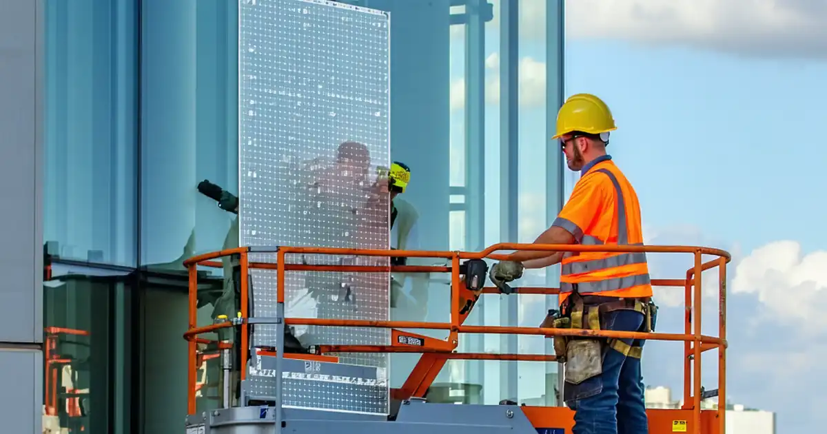
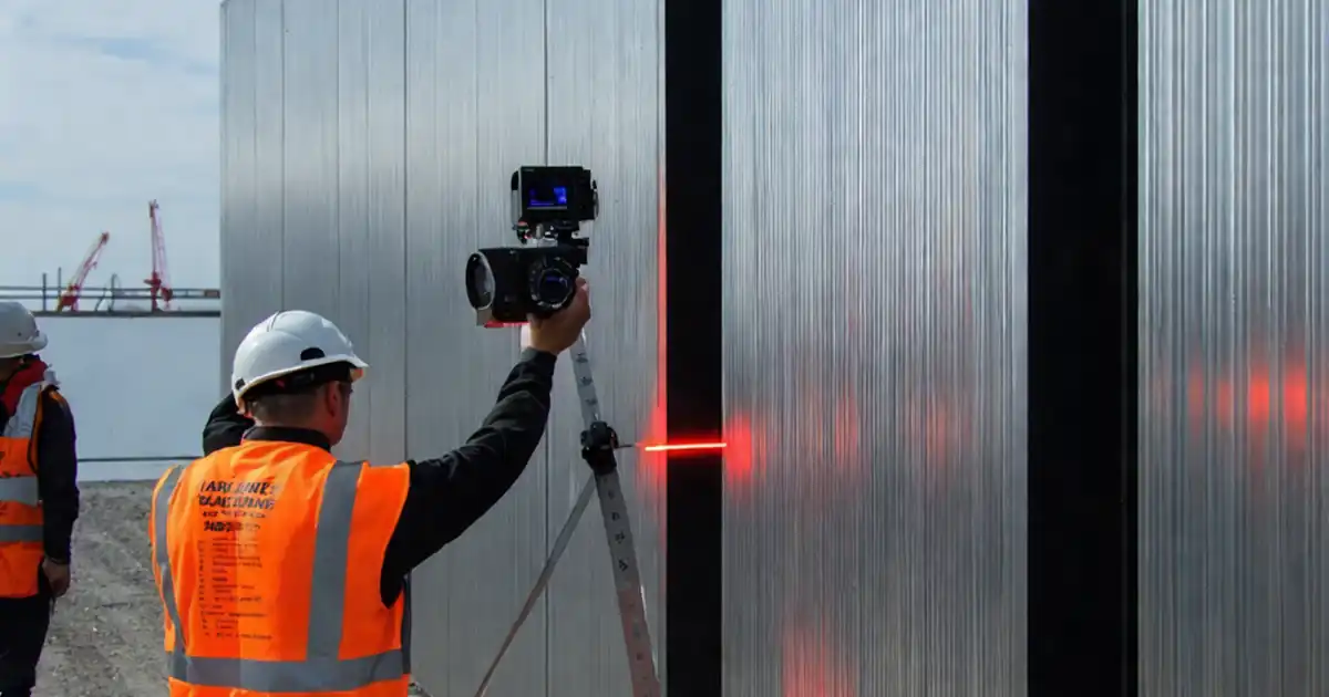
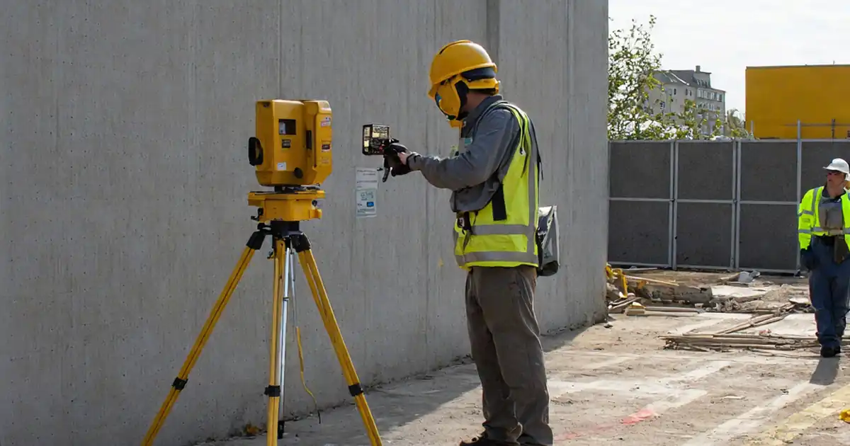
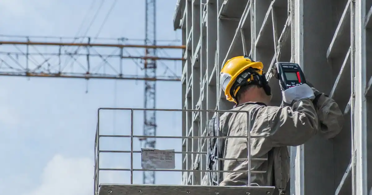
Inspect Façade Optical Alignment and Reflected Image Distortion
Definition: Inspect façade optical alignment and reflected image distortion guides inspectors, contractors, and consultants to evaluate panel flatness, joint alignment, and reflection quality against project tolerances, preventing visual defects, complaints, and costly rework.
- What: verify panel plane, joint uniformity, and reflection consistency.
- Why: avoid visual waviness, misalignment, and client rejection or warranty disputes.
- How: use total station, laser, straightedge, targets, calibrated photography.
- Interactive, commentable, exportable with QR code verification for traceability.
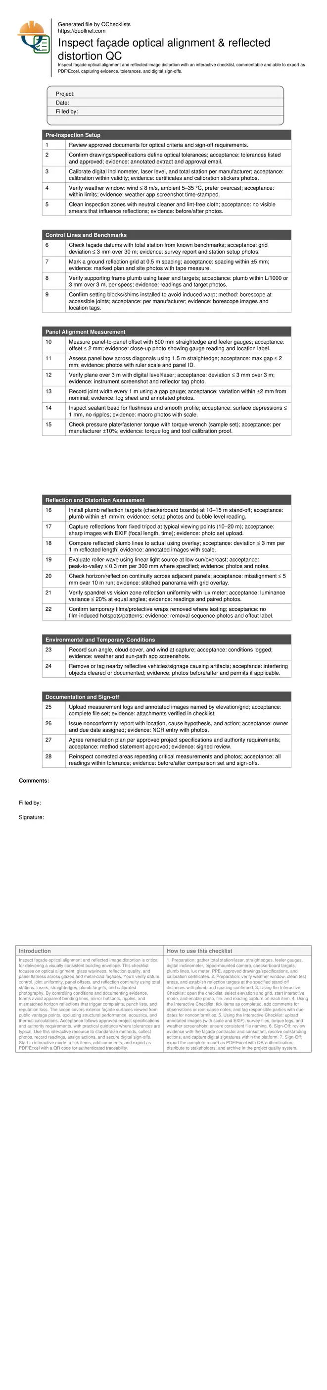
Inspect façade optical alignment and reflected image distortion is critical for delivering a visually consistent building envelope. This checklist focuses on optical alignment, glass waviness, reflection quality, and panel flatness across glazed and metal-clad façades. You’ll verify datum control, joint uniformity, panel offsets, and reflection continuity using total stations, lasers, straightedges, plumb targets, and calibrated photography. By controlling conditions and documenting evidence, teams avoid apparent bending lines, mirror hotspots, ripples, and mismatched horizon reflections that trigger complaints, punch lists, and reputation loss. The scope covers exterior façade surfaces viewed from public vantage points, excluding structural performance, acoustics, and thermal calculations. Acceptance follows approved project specifications and authority requirements, with practical guidance where tolerances are typical. Use this interactive resource to standardize methods, collect photos, record readings, assign actions, and secure digital sign-offs. Start in interactive mode to tick items, add comments, and export as PDF/Excel with a QR code for authenticated traceability.
- Ensure façade planes are true, joints are consistent, and reflections read as straight, continuous lines from common viewing positions. Combine survey control, precise hand measurements, and calibrated photography to detect offsets, bowing, roller-wave, or uneven luminance that produce high-visibility defects.
- Reduce rework and disputes by linking each observation to measurable tolerances, dated photos, EXIF data, and responsible parties. Structured evidence supports quick root-cause analysis, targeted remediation, and transparent approval from façade specialists and client representatives.
- Interactive online checklist with tick, comment, and export features secured by QR code. Use it to centralize measurement logs, annotate reflection images, and maintain a verified audit trail for inspections across elevations, floors, and phases of completion.
- Adapt the method to site-specific constraints while maintaining consistent vantage points, lighting notes, and reflection targets. Overcast conditions and fixed tripod positions improve repeatability, enabling before/after comparisons that validate corrective actions and close out punch items confidently.
Pre-Inspection Setup
Control Lines and Benchmarks
Panel Alignment Measurement
Reflection and Distortion Assessment
Environmental and Temporary Conditions
Documentation and Sign-off
Optical Alignment Fundamentals and Practical Tolerances
Optical alignment depends on consistent façade planes, true joints, and stable support framing. Begin with reliable survey control and instrument calibration. Use straightedges and feeler gauges to quantify offsets and bowing, then confirm larger spans with lasers or a total station. Small variations can produce amplified visual defects when the façade reflects linear features like horizons or surrounding buildings. Practical acceptance limits often sit around 2–3 mm over 1–3 m, but always align with approved project specifications and authority requirements. Document each reading with a photo that includes a scale and location identifier. Note that induced stresses—over-torqued pressure plates, mis-set shims, or tight sealant tooling—can warp glass or panels. Address root causes before cosmetic adjustments. Consistency in method, location, and measurement length enables credible comparisons over time and after remediation.
- Use the same straightedge length for comparable readings.
- Attach a ruler in every alignment photo for scale.
- Reference elevations and gridlines in filenames.
- Sample enough panels to represent each orientation.
- Reconfirm instrument calibration after impacts or drops.
Assessing Reflected Image Distortion with Targets
Reflected distortion reveals subtle waviness that direct measurements miss. Create a controlled scene: plumb checkerboards and string lines at known spacing and distance. Shoot from common viewing points using a fixed tripod and consistent focal length. Overcast light reduces glare and improves edge detection. Compare reflections to the physical targets; curved or broken reflected lines indicate panel bow, roller-wave, or misaligned joints. Capture EXIF data to support repeatability. When evaluating spandrel versus vision zones, measure luminance with a light meter at equal incidence angles. Avoid false readings from protective films, wet glass, or moving reflective objects. Where the specification defines limits (e.g., roller-wave peak-to-valley), record numerical assessments and annotate images to show method and scale.
- Use overcast conditions for consistent reflection images.
- Fix tripod height and focal length for repeats.
- Annotate deviations directly on photos with dimensions.
- Store EXIF and weather data with each image set.
- Eliminate temporary films and glare sources first.
Evidence, Trend Analysis, and Closeout
Reliable evidence links measurements, images, and decisions. Name files by elevation, gridline, and panel ID. Combine logs, survey outputs, and annotated images into a single record. Track trends by plotting offsets and bow against location; clusters often point to installation sequence issues or uneven torque. For nonconformities, record cause hypotheses and corrective actions—retorquing plates, repositioning shims, or panel replacement. Reinspect with the same tools and vantage points to prove improvement. Secure digital sign-offs and archive a QR-authenticated export so stakeholders can verify source data. Clear, structured documentation accelerates approvals and protects all parties if disputes arise later.
- Keep consistent naming across elevations and floors.
- Assign each NCR to a responsible party and due date.
- Repeat measurements post-fix in identical conditions.
- Export a QR-secured PDF/Excel for the project record.
How to Use This Façade Optical Alignment Checklist
- Preparation: gather total station/laser, straightedges, feeler gauges, digital inclinometer, tripod-mounted camera, checkerboard targets, plumb lines, lux meter, PPE, approved drawings/specifications, and calibration certificates.
- Preparation: verify weather window, clean test areas, and establish reflection targets at the specified stand-off distances with plumb and spacing confirmed.
- Using the Interactive Checklist: open the checklist, select elevation and grid, start interactive mode, and enable photo, file, and reading capture on each item.
- Using the Interactive Checklist: tick items as completed, add comments for observations or root-cause notes, and tag responsible parties with due dates for nonconformities.
- Using the Interactive Checklist: upload annotated images (with scale and EXIF), survey files, torque logs, and weather screenshots; ensure consistent file naming.
- Sign-Off: review evidence with the façade contractor and consultant, resolve outstanding actions, and capture digital signatures within the platform.
- Sign-Off: export the complete record as PDF/Excel with QR authentication, distribute to stakeholders, and archive in the project quality system.
Call to Action
- Start Checklist Tick off tasks, leave comments on items or the whole form, and export your completed report to PDF or Excel—with a built-in QR code for authenticity.
- Download Excel - Façade Optical Alignment & Reflection Inspection
- Download PDF - Façade Optical Alignment & Reflection Inspection
- View Image - Façade Optical Alignment & Reflection Inspection
Cite & Embed
“Façade Optical Alignment & Reflection Inspection by Quollnet”
with a link to
this source page.
FAQ
Question: What causes reflected image distortion on façades, and why does it matter?
Question: What tolerances are typical for optical alignment and reflections?
Question: How do weather and lighting affect reflection assessments?
Question: How can I remediate noticeable distortion after installation?
Related Articles
Broader reading and guidance connected to this checklist topic.


Is It Important To Customize Your Qr Code And How To Do It?

Improve Your Project Handover Process With Snag List Tracking App
Related Checklists
Keep the workflow moving with nearby templates chosen from similar checklist content.