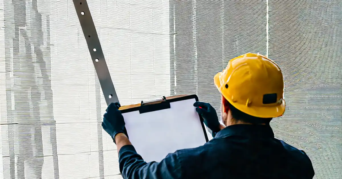
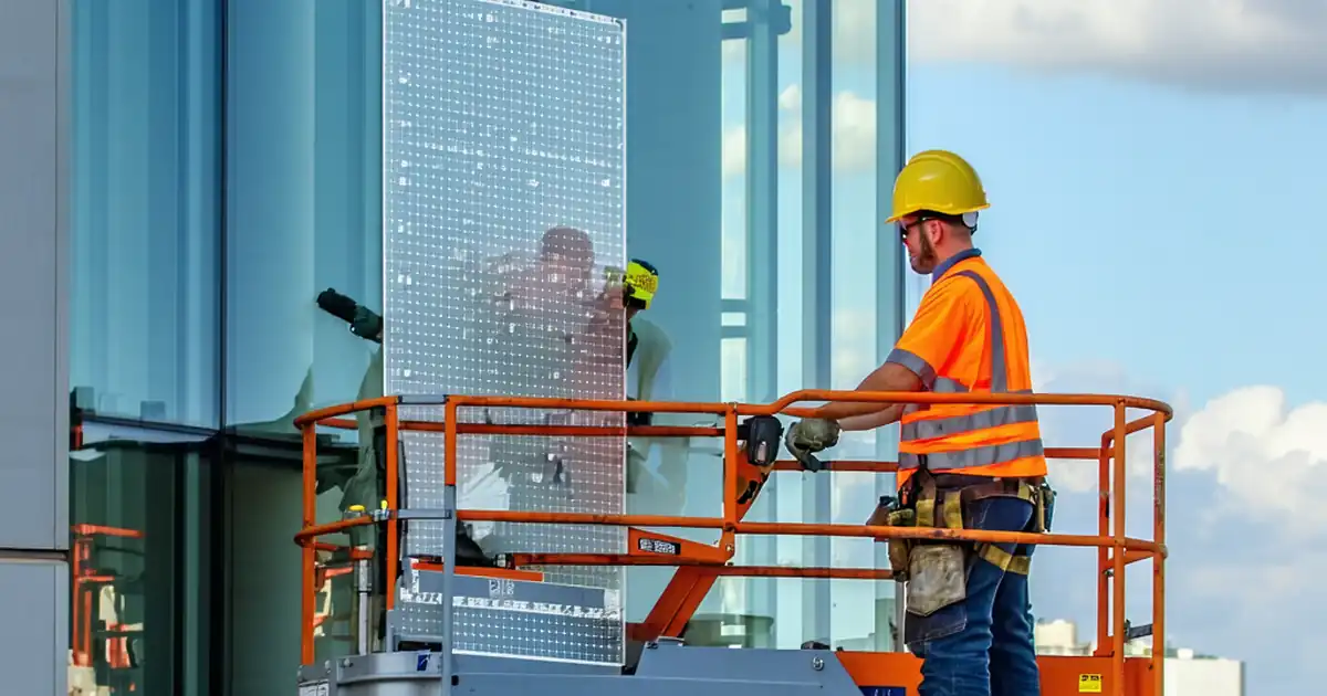
Test façade installed panels for flatness, waviness, and visual tolerances
Definition: Test façade installed panels for flatness, waviness, and visual tolerances using calibrated field methods for construction QA teams, benchmarking against project specifications and capturing evidence with measurements, photos, and digital sign-offs.
- Measure flatness with straightedge, gauge, and laser over defined spans.
- Assess panel waviness via reflection tests at standard viewing distances.
- Verify visual tolerances: joints, alignment, color, gloss, and finishes.
- Interactive, commentable checklist with export and QR code authentication.
Test façade installed panels for flatness, waviness, and visual tolerances is a focused QA procedure verifying installed cladding meets appearance and geometry requirements. This checklist guides façade flatness testing, panel waviness assessment (oil canning), and visual inspection of cladding across representative grids. You will use calibrated tools—straightedges, feeler gauges, laser planes, and controlled lighting—to determine deviations from a defined plane and to judge reflective distortion against the approved mock-up. It also captures joint uniformity, alignment, color and gloss consistency, sealant finish, and any surface defects. By following these steps, teams avoid premature rework, client disputes, and warranty exposure, while ensuring consistent workmanship and traceable results per approved project specifications and authority requirements. Start in interactive mode to tick items, add comments with photos, and export PDF/Excel secured by a QR code for project stakeholders.
- Verify installed façade panels using calibrated straightedges, feeler gauges, and laser planes to measure flatness and array planarity. Structured evidence capture helps teams compare results against approved specifications and mock-up standards, reducing disputes and ensuring repeatable, traceable outcomes on complex building envelopes.
- Evaluate waviness via controlled reflection methods at standard viewing distances under diffuse lighting, documenting ripple depth, telegraphing, and appearance acceptability. Align judgment with the approved mock-up and environmental conditions to avoid subjective calls caused by raking light or temporary thermal stress.
- Interactive online checklist with tick, comment, and export features secured by QR code. Field teams can attach photos, instrument IDs, lot references, and signatures, then distribute a locked, time-stamped PDF/Excel to the contractor, consultant, and client for streamlined closeout.
Pre-Inspection Controls
Measurement Equipment Setup
Flatness Measurement
Waviness Assessment
Visual Tolerances Review
Documentation and Closeout
Flatness: Methods, Targets, and Evidence
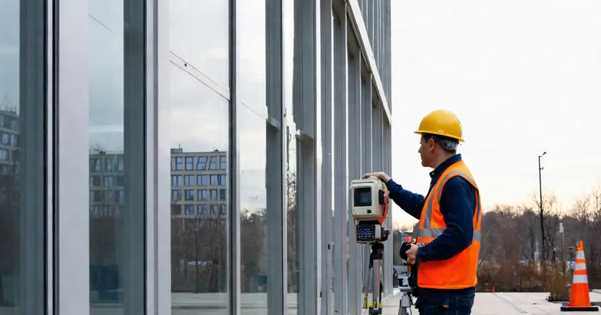
Flatness confirms each panel and the assembled array sit within an acceptable plane. Use a calibrated 2 m straightedge vertically and horizontally, measuring the maximum gap with feeler gauges. Record results in millimetres and annotate each reading to the exact panel ID and grid position. For diagonal checks, a taut string or long straightedge highlights corner lift or bowing. Extend the assessment to an array using a laser plane to reveal global out-of-plane drift across several adjoining panels. Typical targets are expressed as maximum deviation over a stated span (for example, ≤2 mm over 2 m and ≤3 mm over 5 m), but always apply the approved project specifications and authority requirements. Photograph instrument placement and gauges to create objective evidence. Where readings exceed the limit, note fix locations, suspected causes (e.g., subframe shimming), and required rectification. This disciplined approach prevents disputes and ensures repeatable, defensible outcomes acceptable to client and consultant teams.
- Measure vertical, horizontal, and diagonal with a 2 m straightedge.
- Record gaps in millimetres with feeler gauges and photos.
- Check array planarity using a calibrated laser plane.
- Compare to project-specified limits and mock-up cues.
- Annotate elevations to locate and trend deviations.
Waviness: Appearance, Reflection, and Mock-Up Alignment
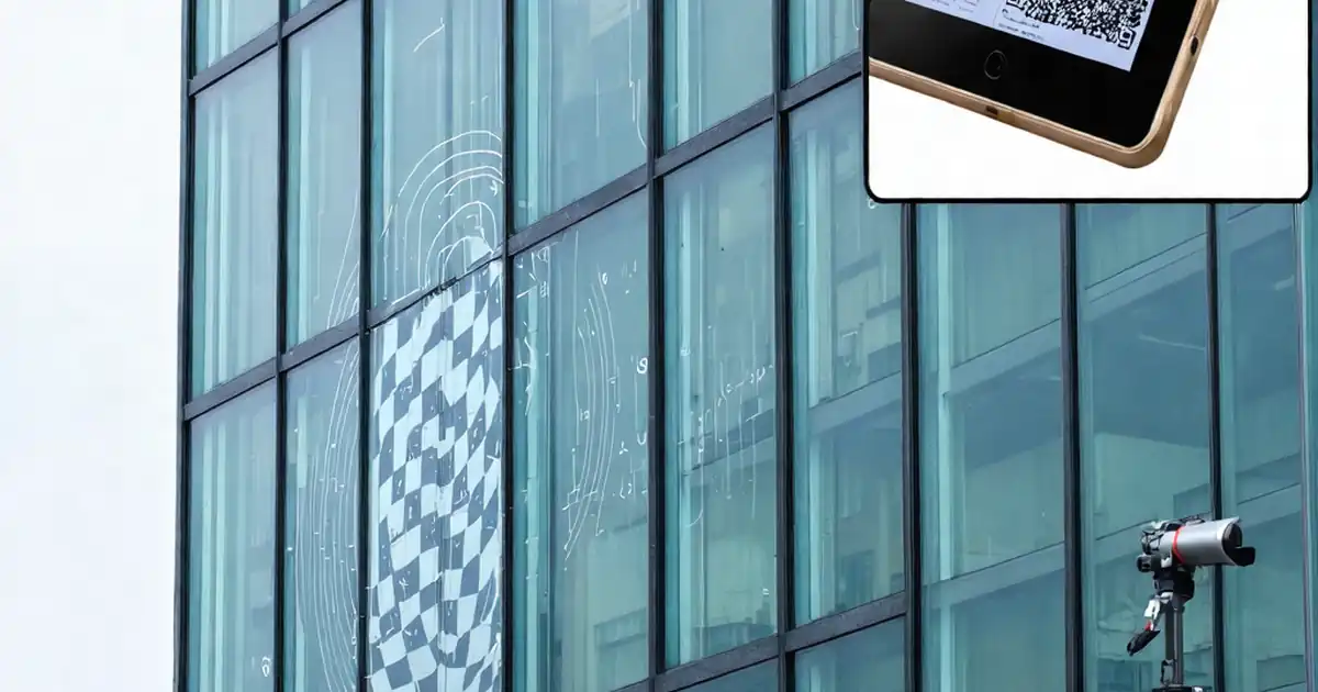
Waviness, or oil canning, is an appearance phenomenon where reflections distort due to panel stresses, thermal effects, or subframe conditions. Evaluate using a high-contrast reflection target at a 3–5 m viewing distance under diffuse lighting; avoid judging under raking light that exaggerates defects. Map distortion zones, then quantify ripple depth by placing a 300 mm straightedge over the depression and measuring the gap with feeler gauges. Compare the observed appearance with the approved mock-up’s photographic standard and acceptance notes. Check for telegraphing of stiffeners or fixings, which can print through thin skins. Photograph normal and oblique views, keeping camera distance and angle consistent for repeatability. If temperature differences are significant, re-check after equilibrium to rule out transient effects. Clear, consistent visuals aligned to the mock-up protect decisions from subjectivity and help prioritize corrective actions with the fabricator and installer.
- Use reflection target at 3–5 m under diffuse light.
- Quantify ripple depth with a 300 mm straightedge.
- Avoid raking light that exaggerates waviness.
- Benchmark against the approved mock-up standard.
- Document oblique and normal views consistently.
Visual Tolerances: Joints, Alignment, Color, and Finish
Visual tolerances govern overall façade appearance beyond geometry. Measure joint widths with calipers or gauges at regular stations to establish mean and range, then verify long-run alignment with a string line over 5 m segments. Inspect sealant beads for width, continuity, and tooling quality. Assess color and gloss under standardized lighting (D65 or a calibrated lightbox); if instruments are available, capture ΔE and gloss units for objective comparison. Survey edges, corners, and coatings for scratches, dents, and abrasions, and verify that fasteners match the system’s intended exposure. Acceptance should follow the approved project specifications and mock-up benchmarks, not arbitrary field judgments. Record each observation with time-stamped photos, panel IDs, and locations on an elevation mark-up. This combination of measurements and visual cues ensures a façade that reads straight, uniform, and consistent under everyday viewing conditions.
- Check joint width and alignment over defined runs.
- Verify sealant size, continuity, and tooling finish.
- Assess color and gloss under standardized lighting.
- Log defects with locations and time-stamped photos.
How to Use the Interactive Façade Testing Checklist
- Preparation: Gather tools (2 m straightedge, 300 mm straightedge, feeler gauges, laser plane/line level, string line, caliper, lux meter), PPE, access equipment, drawings, and mock-up references.
- Calibrate and verify instruments; photograph calibration labels and note serial numbers. Confirm safe access and environmental conditions suitable for appearance checks.
- Open the checklist, select the elevation/area, and load project-specified tolerances and mock-up images into the reference section.
- Using the Interactive Checklist: Tick each item as completed, add measurements in millimetres, and attach photos or short videos showing tool placement and readings.
- Use comments to flag nonconformances, tag panel IDs, assign responsible parties, and set due dates. Mention likely causes and proposed fixes.
- Review the dashboard summary to confirm all grid points were sampled and that evidence is complete for each acceptance criterion.
- Export the record as PDF/Excel with embedded photos and a QR code for authenticity, then share to the project CDE for review.
- Sign-Off: Capture digital signatures from inspector, subcontractor, and consultant; archive the QR-secured file with instrument IDs and date-time stamps.

Call to Action
- Start Checklist Tick off tasks, leave comments on items or the whole form, and export your completed report to PDF or Excel—with a built-in QR code for authenticity.
- Download Excel - Façade Panel Flatness, Waviness & Visual Tolerance Test
- Download PDF - Façade Panel Flatness, Waviness & Visual Tolerance Test
- View Image - Façade Panel Flatness, Waviness & Visual Tolerance Test
Cite & Embed
“Façade Panel Flatness, Waviness & Visual Tolerance Test by Quollnet”
with a link to
this source page.

FAQ
Question: What’s the difference between flatness and waviness on façade panels?
Question: Which lighting conditions are best for evaluating panel waviness?
Question: How many measurement points per elevation are recommended?
Question: How should nonconformances be documented and closed out?
Related Articles
Broader reading and guidance connected to this checklist topic.




Concrete Core Test Guide: Astm C42, Aci 318-25 & Bs En 13791
Related Checklists
Keep the workflow moving with nearby templates chosen from similar checklist content.