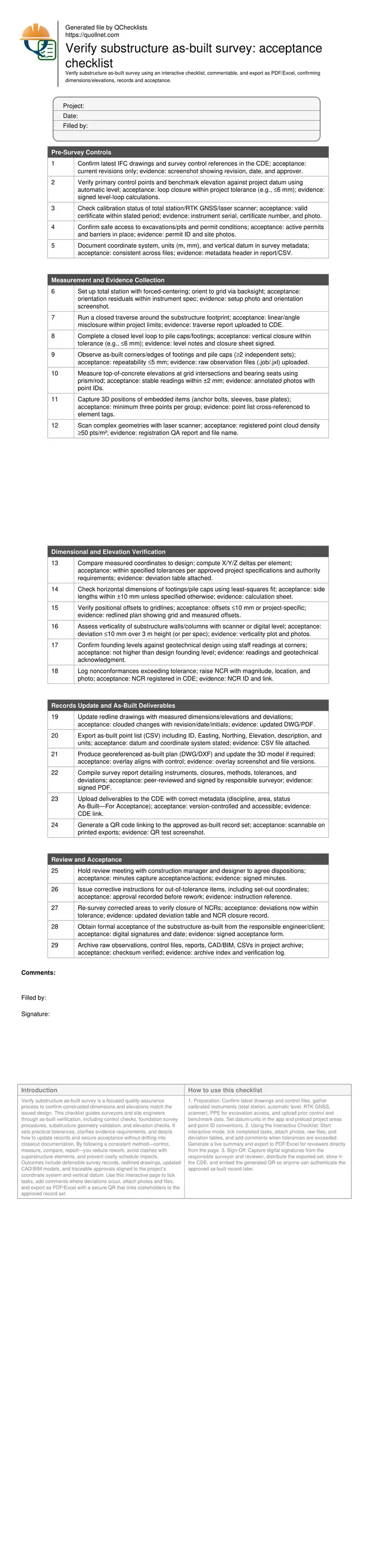
Verify Substructure As-Built Survey: Acceptance Checklist
Definition: Verify substructure as-built survey for contractors and surveyors, confirming built dimensions and elevations against issued drawings, updating records, capturing evidence, and documenting acceptance, excluding final closeout documentation.
- Confirm dimensions and elevations against latest IFC drawings and datum.
- Control, measure, compare, and document with clear tolerances and evidence.
- Drive acceptance decisions and corrective actions per approved project specifications.
- Interactive, commentable, export, QR code for authenticated deliverables.
Verify substructure as-built survey is a focused quality-assurance process to confirm constructed dimensions and elevations match the issued design. This checklist guides surveyors and site engineers through as-built verification, including control checks, foundation survey procedures, substructure geometry validation, and elevation checks. It sets practical tolerances, clarifies evidence requirements, and details how to update records and secure acceptance without drifting into closeout documentation. By following a consistent method—control, measure, compare, report—you reduce rework, avoid clashes with superstructure elements, and prevent costly schedule impacts. Outcomes include defensible survey records, redlined drawings, updated CAD/BIM models, and traceable approvals aligned to the project’s coordinate system and vertical datum. Use this interactive page to tick tasks, add comments where deviations occur, attach photos and files, and export as PDF/Excel with a secure QR that links stakeholders to the approved record set.
- Establish reliable control, measure substructure geometry with repeatable methods, and compute deltas to design. Clear acceptance criteria help you isolate out-of-tolerance items early, preventing misaligned superstructure works, anchor bolt conflicts, or insufficient bearing elevations that could trigger rework and delay subsequent trades and inspections.
- Interactive online checklist with tick, comment, and export features secured by QR code. This enables field teams and reviewers to trace decisions back to raw data, deviation tables, and redlined drawings, ensuring the accepted as-built record is authenticated, version-controlled, and accessible through a single source of truth in the project CDE.
- Produce ready-to-approve deliverables—signed survey reports, CSV point lists, georeferenced DWG/DXF, and updated models—clearly stating coordinate system, datum, instruments, closures, and measured tolerances. Document corrective actions and re-surveys so acceptance is auditable, while excluding broader project closeout packages such as O&M manuals or warranties.
Pre-Survey Controls
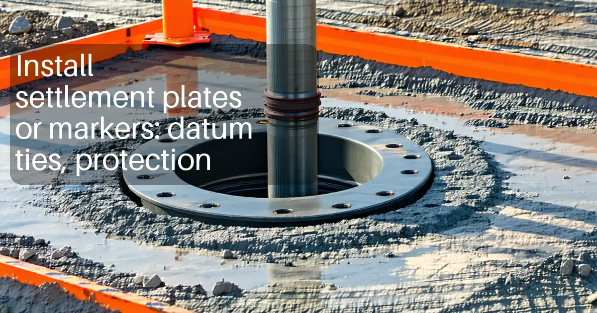
Measurement and Evidence Collection
Dimensional and Elevation Verification
Records Update and As-Built Deliverables
Review and Acceptance
Control first: reliable datums and stable setups
A dependable as-built begins with a dependable framework. Before any measurement, verify the project coordinate system, vertical datum, and the health of control points and benchmarks. Close a level loop to the substructure work area to quantify vertical reliability, and run a closed traverse to lock down horizontal control. Record instrument calibration status and site access constraints, especially around excavations, shoring, and pits. Stable setups, forced-centering, and well-chosen backsights reduce blunders and improve repeatability when measuring footings, pile caps, walls, and embedded items. Treat this phase as a gate: if closures or metadata are incomplete, do not proceed. Consistency here ensures that subsequent comparisons to drawings or the model are meaningful, defendable, and quickly accepted by the designer or client, saving time later when deviations require discussion or corrective action.
- Verify coordinate system and datum before any measurement.
- Close level loops and traverses within project tolerances.
- Record calibration details and instrument serial numbers.
- Use stable setups and forced-centering techniques.
- Gate progress if control or metadata is incomplete.
Compare measured geometry to design with clear tolerances
Once the substructure is captured, compare measured coordinates to the latest IFC drawings or federated model. Compute X/Y/Z deltas for corners, edges, and bearing surfaces, and check positional offsets to gridlines. Use least-squares fits to obtain robust dimensions for footings and pile caps. Evaluate verticality of walls and columns using laser scans or digital levels, then test founding levels at corners to confirm the structure bears where intended. Any exceedance over specified tolerances should automatically create a nonconformance for review. Keep each decision traceable: link measurements to point IDs, photos, raw files, and calculation sheets. Designers can then assess structural intent versus minor dimensional drift and decide acceptance, concession, or rework based on quantified evidence, not impressions.
- Compute and table all X/Y/Z deltas.
- Fit dimensions; avoid relying on a single edge.
- Check grid offsets and verticality per spec.
- Test founding levels at representative points.
- Open NCRs for out-of-tolerance items.
Deliverables that secure acceptance and future traceability
Acceptance depends on clear, consistent deliverables: revised drawings with clouded changes, a signed survey report detailing methods and closures, CSV point lists with datums and units, and georeferenced DWG/DXF overlays that align with control. If geometry is complex, attach a registered point cloud and QA summary. Upload everything to the CDE with complete metadata and set status to As-Built—For Acceptance so stakeholders know the intent. A QR code on printed exports links reviewers to the controlled version, eliminating outdated copies. Finally, document any corrective instructions and re-surveys, then close NCRs with evidence. This package excludes broader closeout materials, staying focused on substructure as-built verification and acceptance only.
- Redline drawings with deviations clearly clouded.
- Signed report summarizing methods and closures.
- CSV and DWG/DXF aligned to control and datum.
- CDE upload with correct metadata and status.
- QR secures the current approved record set.
How to Use This Interactive Checklist
- Preparation: Confirm latest drawings and control files, gather calibrated instruments (total station, automatic level, RTK GNSS, scanner), PPE for excavation access, and upload prior control and benchmark data. Set datum/units in the app and preload project areas and point ID conventions.
- Using the Interactive Checklist: Start interactive mode, tick completed tasks, attach photos, raw files, and deviation tables, and add comments when tolerances are exceeded. Generate a live summary and export to PDF/Excel for reviewers directly from the page.
- Sign-Off: Capture digital signatures from the responsible surveyor and reviewer, distribute the exported set, store in the CDE, and embed the generated QR so anyone can authenticate the approved as-built record later.
Call to Action
- Start Checklist Tick off tasks, leave comments on items or the whole form, and export your completed report to PDF or Excel—with a built-in QR code for authenticity.
- Download Excel - Substructure As-Built Survey Verification
- Download PDF - Substructure As-Built Survey Verification
- View Image - Substructure As-Built Survey Verification
Cite & Embed
“Substructure As-Built Survey Verification by Quollnet”
with a link to
this source page.
FAQ
Question: What tolerances should I use for substructure as-built verification?
Question: Do I need a laser scanner, or is a total station sufficient?
Question: When should the as-built survey be performed?
Question: How do I handle out-of-tolerance results?
Related Articles
Broader reading and guidance connected to this checklist topic.


Is It Important To Customize Your Qr Code And How To Do It?


Master Construction Project Cashflow With Cashflowpot
Related Checklists
Keep the workflow moving with nearby templates chosen from similar checklist content.