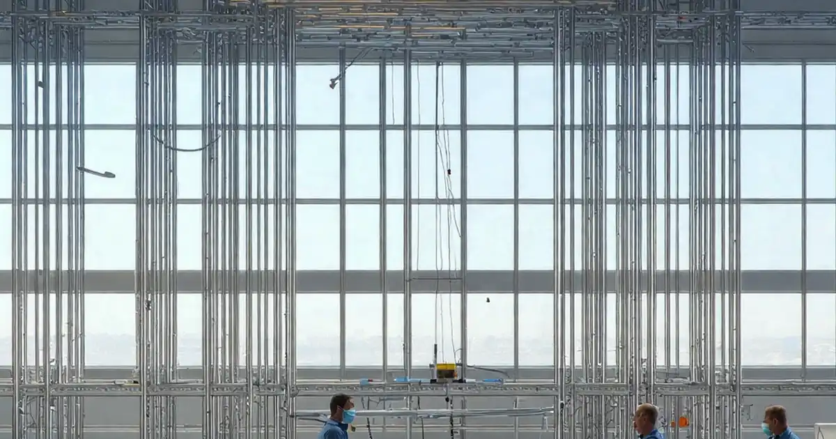
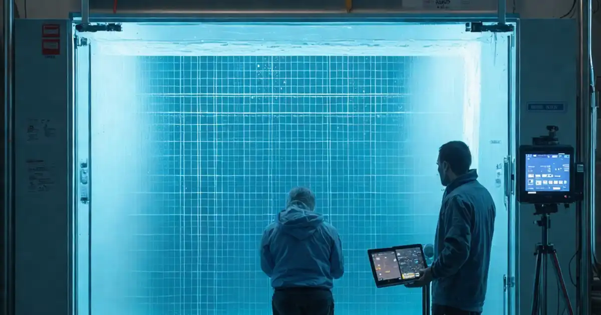
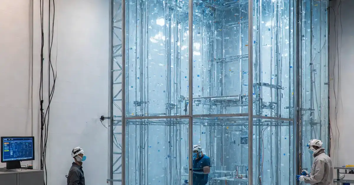
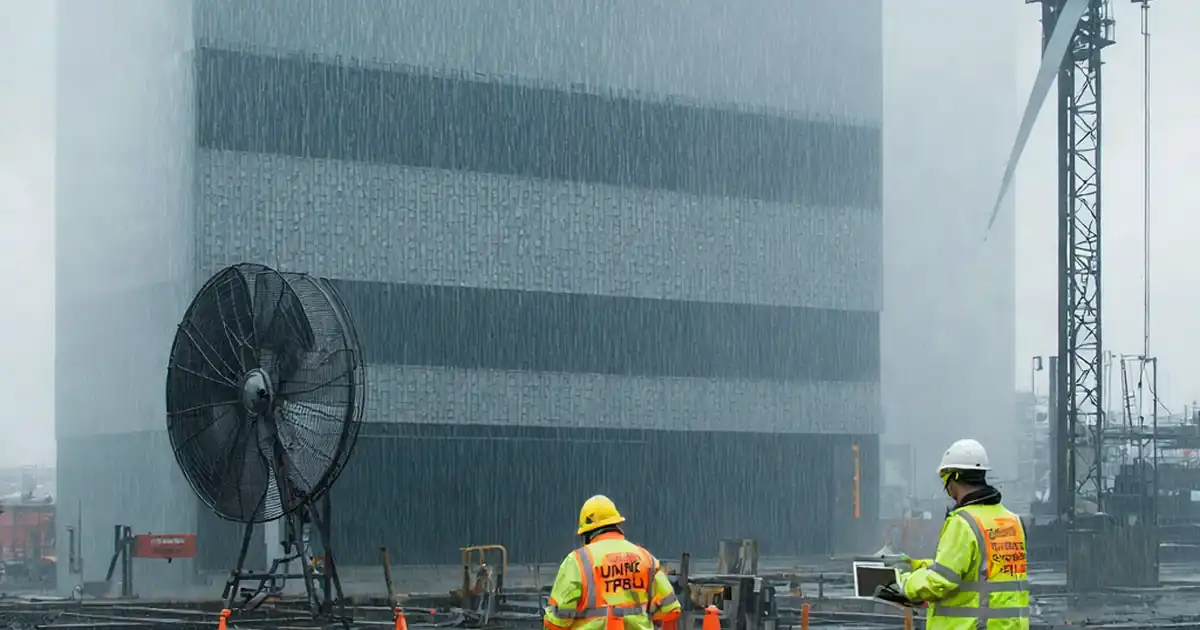
Test façade mock-up for structural deflection under design wind load
Definition: Test façade mock-up for structural deflection under design wind load guides façade engineers and QA teams through instrumented, repeatable lab testing to verify serviceability performance, acceptance limits, and documented evidence under positive and negative pressure.
- Instrumented method to measure out-of-plane deflection at design pressure
- Why it matters: prevent cracking, anchor slip, and warranty claims
- How to do it: calibrated sensors, controlled pressure, documented acceptance
- Interactive, commentable checklist; export reports with QR code verification
Test façade mock-up for structural deflection under design wind load establishes a consistent, instrumented process to validate façade serviceability before field installation. This checklist focuses on curtain wall deflection testing at design wind pressure using a sealed pressure chamber, calibrated differential pressure transducers, and displacement sensors such as LVDTs or laser gauges. The scope is limited to structural deflection behavior of the mock-up assembly (mullions, transoms, anchors, and interfaces) under positive and negative pressure; it excludes air or water penetration testing. By controlling ramp rates, hold times, and sensor sampling, teams capture maximum and residual deflection to compare against serviceability criteria per approved project specifications and authority requirements. Clear documentation—plots, photos, calibration records, and sign-offs—reduces disputes, prevents cracking or fastener slip, and protects warranties. Use this interactive page to plan, run, and record the test effectively—tick items, leave comments, and export the full record as PDF/Excel with a secure QR code.
- Define the test protocol, calibrate instruments, and instrument critical mullions and transoms to quantify out-of-plane deflection at design wind pressure. Structured preparation minimizes measurement error, supports safety, and ensures results are reproducible and defensible for project acceptance.
- Execute controlled pressure cycles with verified chamber stability, measured ramp rates, and adequate hold durations. Capture continuous displacement data at a suitable sampling rate, monitor for visible distress, and record environmental conditions to contextualize results and support reliable trend analysis.
- Interpret maximum and residual deflection against project serviceability criteria, compute any required deflection ratios, and assemble a complete, traceable report. Immediate nonconformance logging and corrective actions accelerate resolution and reduce schedule and financial risks.
- Interactive online checklist with tick, comment, and export features secured by QR code. Teams can attach photos, calibration certificates, and data plots, then generate a signed PDF/Excel dossier that aligns stakeholders and streamlines authority or third-party reviews.
Pre-Test Documentation
Mock-Up Preparation
Instrumentation and Calibration
Load Application and Monitoring
Post-Test and Acceptance
Purpose and scope of façade deflection testing
Deflection testing of a façade mock-up at design wind pressure confirms the structural serviceability of mullions, transoms, anchors, and interfaces before field installation. By applying controlled positive and negative pressure cycles in a sealed chamber and monitoring displacement with calibrated sensors, teams establish peak and residual deflection values for comparison against project criteria. This targeted scope excludes air or water penetration assessments and focuses solely on out-of-plane structural response. Practical acceptance cues include stable chamber pressure, linear sensor response, and consistent readings across repeated steps. On real projects, early mock-up validation has prevented cracked glazing, fastener slip, and misaligned interfaces by flagging stiffness shortfalls before procurement. The outcome is a traceable, low-ambiguity record—plots, photos, and sign-offs—that supports approvals by designers, clients, and authorities. Disciplined preparation, instrumentation, and documentation transform a potentially subjective inspection into a quantitative, defendable verification of façade performance under expected wind loading.
- Limit scope to structural deflection under wind loading
- Stabilize pressure; avoid oscillations during holds
- Use calibrated, rigidly mounted displacement sensors
- Capture both maximum and residual deflection values
- Document everything with plots, photos, and sign-offs
Setting up instrumentation for reliable readings
Reliable deflection data depends on how sensors are mounted, zeroed, and sampled. Use rigid, independent frames so LVDTs or laser gauges reference a stable datum, not the test rig. Align probes normal to the surface to prevent cosine error, and secure cables to avoid vibration-induced noise. Establish a sampling rate of at least 10 Hz, synchronized time stamps, and clear channel naming by location. Confirm zero drift and linear response with a low trial load before applying significant pressure. Pressure transducers should cover at least 1.2 times the design wind pressure to avoid overrange, and their accuracy should be verified with recent calibration records. Simple pretests—like a brief 0.20 kPa hold—can reveal sealing issues or control instability that would otherwise compromise results. Careful setup yields smooth traces, predictable hysteresis, and interpretable peaks and recoveries, making later acceptance decisions straightforward and defensible.
- Reference sensors to rigid, independent frames
- Align probes normal to minimize cosine error
- Sample ≥ 10 Hz with synchronized time
- Verify zero drift and linear response
- Check pressure stability before main test
Executing load cycles and interpreting results
Run stepwise loading to 50%, 75%, and 100% of design pressure with a controlled ramp, holding each plateau long enough for deflection to stabilize. At the design plateau, capture peak values and watch for visible distress, then return to zero to measure residual deflection. Repeat the full sequence under suction to evaluate bidirectional performance. Stable pressure (minimal oscillation) and smooth deflection traces indicate good test control; sudden jumps may signal slippage or contact. Compute any required deflection ratios per the project method and compare against serviceability criteria per approved project specifications and authority requirements. Contextualize results by logging ambient temperature and relative humidity. Package plots, maxima, residuals, photos, and calibration evidence into a signed report. When exceedances occur, promptly record nonconformances, assign corrective actions, and consider design adjustments or reinforcement before retesting.
- Use controlled ramp and defined holds
- Measure both positive and negative pressure
- Track peak and residual deflection
- Watch for distress at load peaks
- Report ratios and acceptance clearly
How to Use This Interactive Checklist
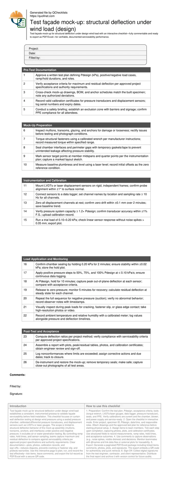
- Preparation: Confirm the test plan, Pdesign, acceptance criteria, tools (torque wrench, LVDTs/laser gauges, data logger, pressure transducer), seals, and PPE. Verify calibrations are current and the chamber, blower, and power supply are service-ready.
- Open the checklist in interactive mode. Enter project, specimen ID, Pdesign, date/time, and responsible roles. Attach drawings and the approved test plan for reference before starting physical setup.
- Assign items to team members. Tick each step upon completion, capturing photos, plots, and calibration certificates. Use structured fields to record measurements, ramp rates, hold times, and acceptance outcomes.
- Use comments to capture observations (e.g., noise spikes, visible distress) and decisions. Mention teammates with @names and link data files or external plots for traceability.
- Export: Generate a paginated PDF/Excel package including ticked items, comments, photos, plots, and signatures. The export embeds a QR code for authenticity and quick retrieval.
- Sign-Off: Collect digital signatures from the test engineer, contractor, and client representative. Distribute the final report and archive it with version control for future audits.
Call to Action
- Start Checklist Tick off tasks, leave comments on items or the whole form, and export your completed report to PDF or Excel—with a built-in QR code for authenticity.
- Download Excel - Façade Mock-Up Deflection Test (Design Wind Load)
- Download PDF - Façade Mock-Up Deflection Test (Design Wind Load)
- View Image - Façade Mock-Up Deflection Test (Design Wind Load)
Cite & Embed
“Façade Mock-Up Deflection Test (Design Wind Load) by Quollnet”
with a link to
this source page.

FAQ
Question: What mock-up size and configuration should be used for deflection testing?
Question: Where should displacement sensors be placed and at what sampling rate?
Question: What if measured deflection exceeds acceptance limits?
Question: Can the same setup be used for water or air tests too?
Related Articles
Broader reading and guidance connected to this checklist topic.


How To Perform a Concrete Compressive Strength Test: Cubes & Cylinders
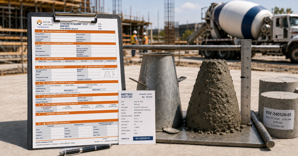
Concrete Slump Test Report Template

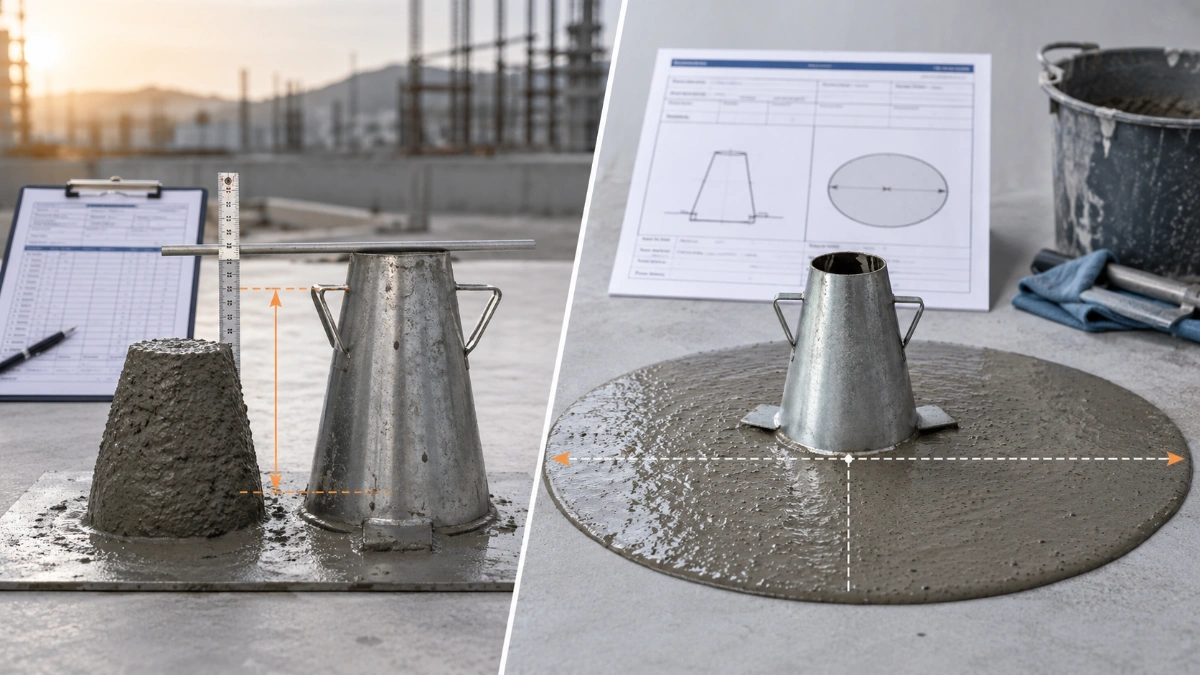
Slump Test Vs Slump Flow Test: When To Use Each
Related Checklists
Keep the workflow moving with nearby templates chosen from similar checklist content.