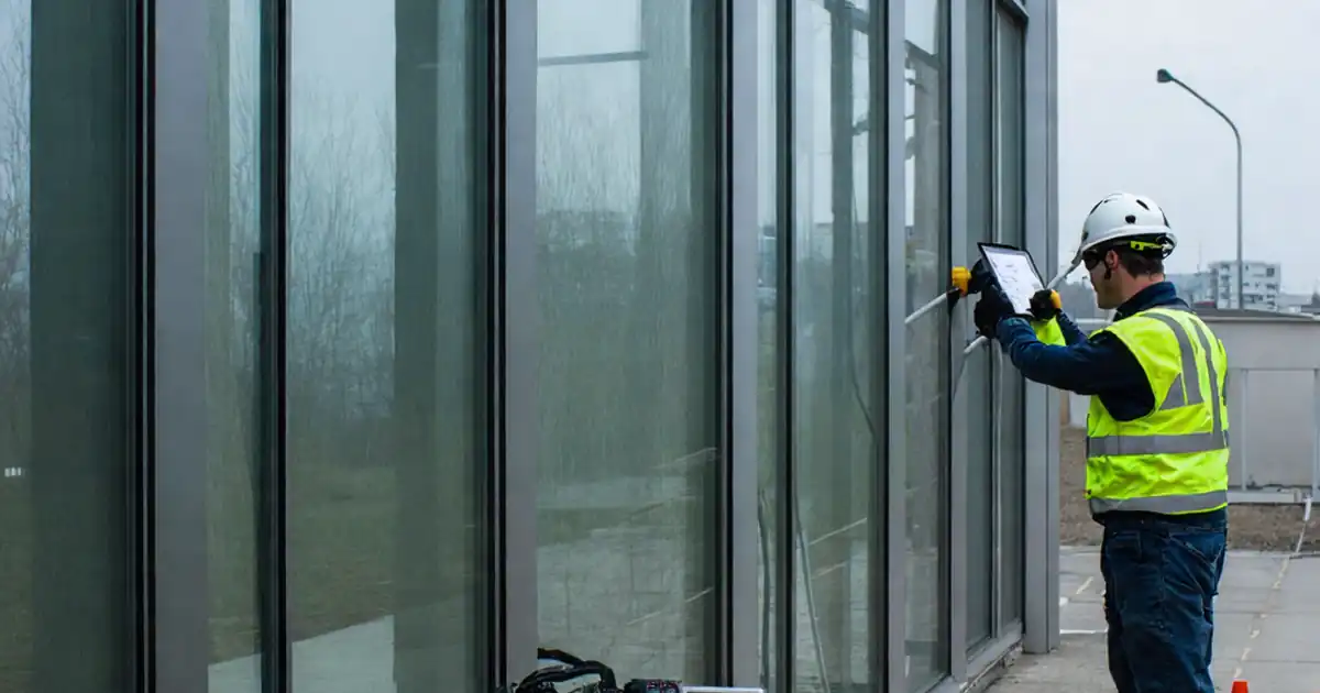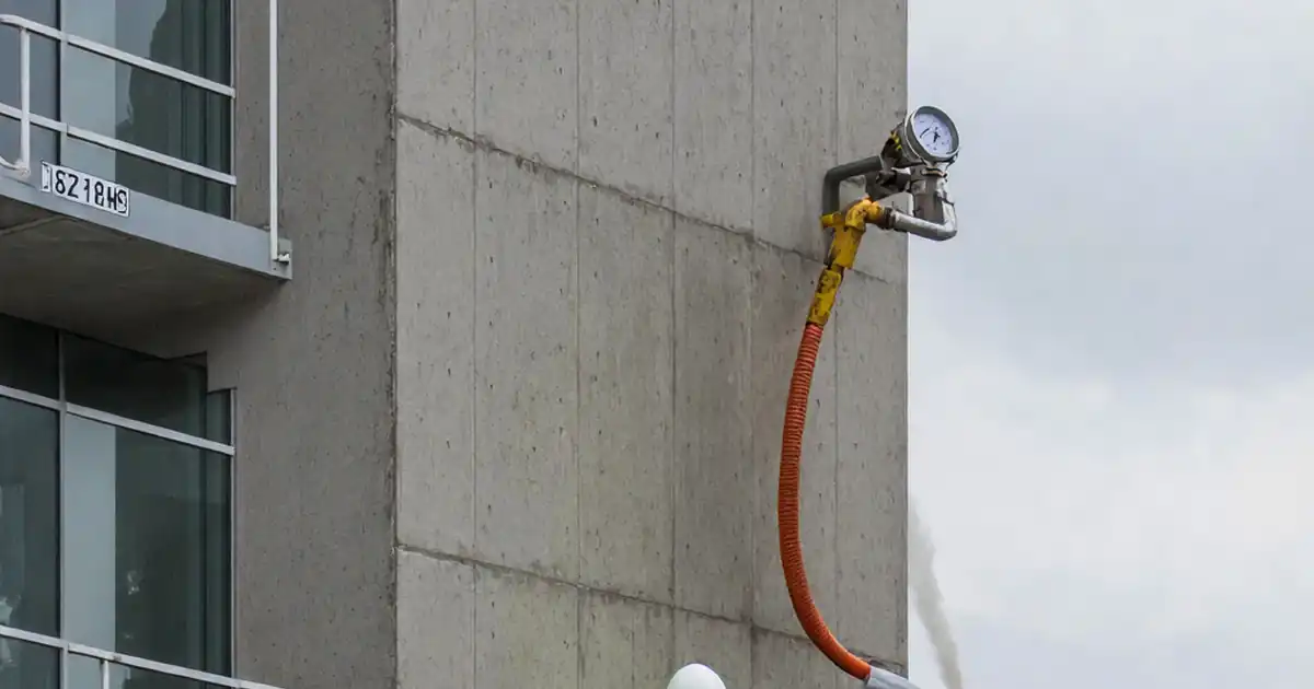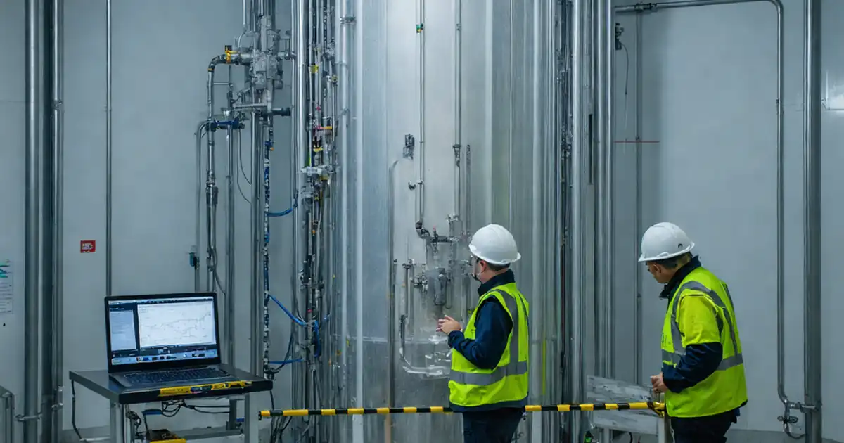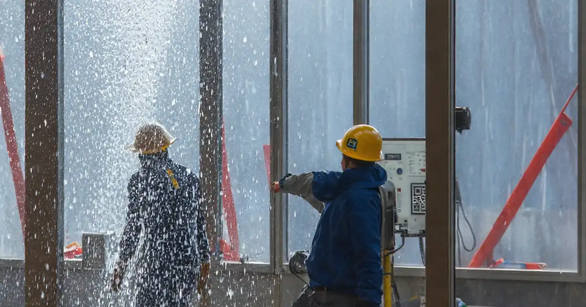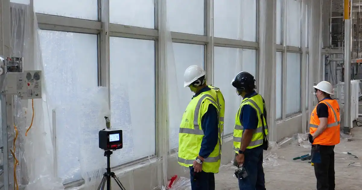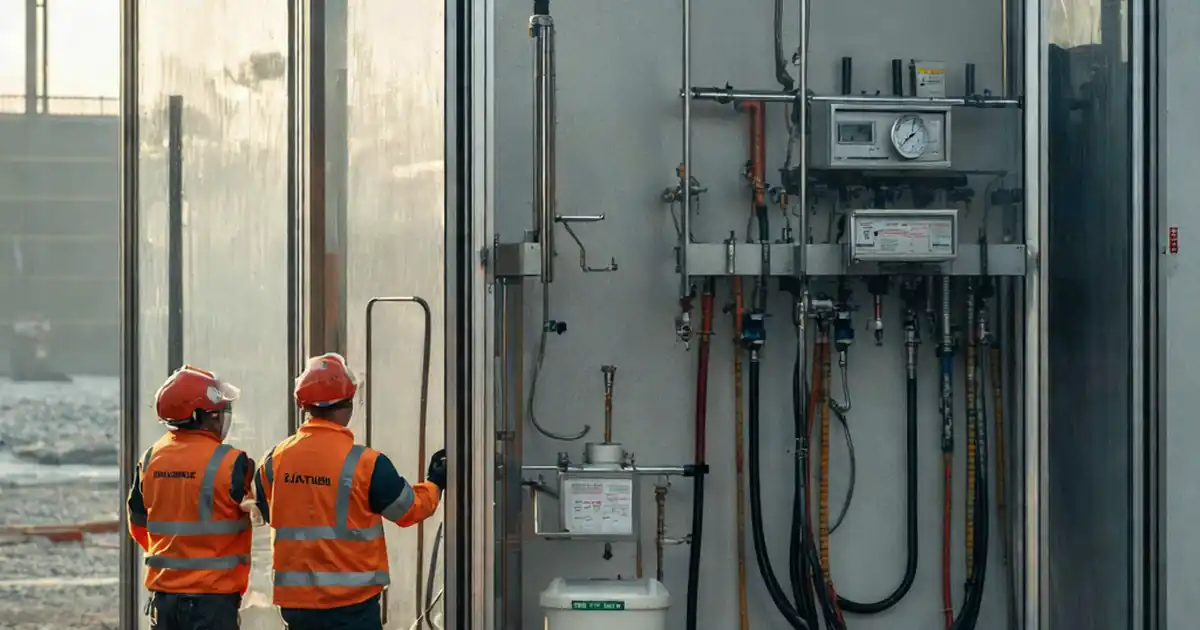
Inspect façade water-tightness test setup before testing is a pre-test checklist for site engineers verifying chamber integrity, spray uniformity, instruments, water supply, and safety controls to avoid invalid results.
- Verify chamber sealing, pressure control, and uniform spray coverage.
- Confirm calibrated instruments, flow stability, and traceable documentation.
- Reduce rework by catching leaks, gaps, and misaligned fixtures early.
- Interactive, commentable, export, QR code for authenticated records.
The checklist
Test Equipment & Calibration
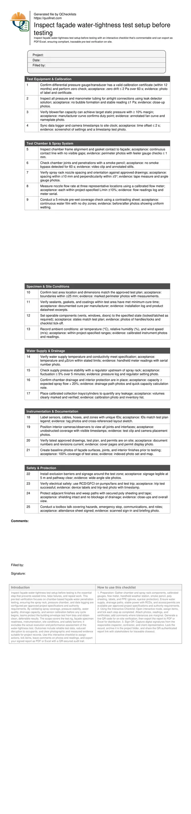
- Confirm differential pressure gauge/transducer has a valid calibration certificate (within 12 months) and perform zero check; acceptance: zero drift ≤ 2 Pa over 60 s; evidence: photo of label and certificate.
- Inspect all pressure and manometer tubing for airtight connections using leak detector solution; acceptance: no bubble formation and stable reading ±1 Pa; evidence: close-up photos.
- Verify blower/fan capacity can achieve target static pressure with ≥ 10% margin; acceptance: manufacturer curve confirms duty point; evidence: annotated fan curve and nameplate photo.
- Sync data logger and camera timestamps to site clock; acceptance: time offset ≤ 2 s; evidence: screenshot of settings and a timestamp test photo.
Test Chamber & Spray System
- Inspect chamber frame alignment and gasket contact to façade; acceptance: continuous contact line with no visible gaps; evidence: perimeter photos with feeler gauge checks ≤ 1 mm.
- Check chamber joints and penetrations with a smoke pencil; acceptance: no smoke bypass detected for 60 s; evidence: video clip and annotated stills.
- Verify spray rack nozzle spacing and orientation against approved drawings; acceptance: spacing within ±10 mm and perpendicularity within ±5°; evidence: tape measure and angle gauge photos.
- Measure nozzle flow rate at three representative locations using a calibrated flow meter; acceptance: each within project-specified L/min ±10%; evidence: flow readings log and meter serial.
- Conduct a 5-minute pre-wet coverage check using a contrasting sheet; acceptance: continuous water film with no dry zones; evidence: before/after photos showing uniform wetting.
Specimen & Site Conditions
- Confirm test area location and dimensions match the approved test plan; acceptance: boundaries within ±25 mm; evidence: marked perimeter photos with measurements.
- Verify sealants, gaskets, and coatings within test area have met minimum cure time; acceptance: documented cure per manufacturer; evidence: installation log and product datasheet excerpts.
- Set operable components (vents, windows, doors) to the specified state (locked/latched as required); acceptance: states match test plan; evidence: photos of handles/locks and checklist tick-off.
- Record ambient conditions: air temperature (°C), relative humidity (%), and wind speed (m/s); acceptance: within project-specified ranges; evidence: calibrated instrument photos and readings.
Water Supply & Drainage
- Verify water supply temperature and conductivity meet specification; acceptance: temperature and µS/cm within stated limits; evidence: handheld meter readings with serial number photo.
- Check supply pressure stability with a regulator upstream of spray rack; acceptance: fluctuation ≤ 5% over 5 minutes; evidence: pressure log and regulator setting photo.
- Confirm chamber drainage and interior protection are in place; acceptance: capacity ≥ expected spray flow + 20%; evidence: drainage path photos and quick capacity calculation note.
- Place calibrated collection trays/cylinders to quantify any leakage; acceptance: volumes clearly marked and verified; evidence: calibration photo and inventory list.
Instrumentation & Documentation
- Label sensors, cables, hoses, and zones with unique IDs; acceptance: IDs match test plan legend; evidence: tag photos and cross-referenced layout sketch.
- Position interior cameras/observers to view all joints and interfaces; acceptance: unobstructed coverage with visible timestamps; evidence: test clip and camera placement photos.
- Verify latest approved drawings, test plan, and permits are on site; acceptance: document numbers and revisions current; evidence: cover pages and permit display photo.
- Create baseline photos of façade surfaces, joints, and interior finishes prior to testing; acceptance: 100% coverage of test area; evidence: indexed photo set and map.
Safety & Protection
- Install exclusion barriers and signage around the test zone; acceptance: signage legible at 5 m and pathway clear; evidence: wide-angle site photos.
- Verify electrical safety: use RCD/GFCI on pumps/fans and test trip; acceptance: trip test successful; evidence: device labels and trip-test photo with timestamp.
- Protect adjacent finishes and weep paths with secured poly sheeting and tape; acceptance: shielding intact and no blockage of drainage; evidence: close-ups and overall view.
- Conduct a toolbox talk covering hazards, emergency stop, communications, and roles; acceptance: attendance sheet signed; evidence: scanned sign-in and briefing photo.
Preview the printable checklist
Preview page one below. Open the image or download the PDF for all pages.
At a glance
- Validate chamber sealing, spray rack alignment, and instrument calibration so the test begins under controlled, repeatable conditions. Capture evidence with time-stamped photos, measured readings, and certificates to support quality, compliance, and dispute-free outcomes.
- Assure specimen readiness by confirming cure times, closure states, and boundary locations. Verify water supply quality, pressure regulation, and drainage capacity to eliminate variables that commonly cause inconclusive or rejected water-tightness results and costly retests.
- Interactive online checklist with tick, comment, and export features secured by QR code.
- Coordinate safety and operations: define an exclusion zone, RCD-protect all powered equipment, and brief the team on emergency shutdown. Standardize documentation with unique IDs, synced clocks, and as-built references to strengthen traceability and closeout packages.
How to prepare and use this interactive pre-test checklist
- Preparation: Gather chamber and spray rack components, calibrated gauges, flow meter, handheld weather station, smoke pencil, poly sheeting, labels, and PPE (gloves, eye/ear protection). Ensure water supply, drainage paths, stable power with RCDs, and access/permits are available per approved project specifications and authority requirements.
- Using the Interactive Checklist: Open interactive mode, assign items, and tick each step as completed. Attach photos, readings, and certificates; add comments where tolerances are marginal. Generate a live QR code for on-site verification, then export the report to PDF or Excel for distribution.
- Sign-Off: Capture digital signatures from the responsible inspector, contractor, and client representative. Lock the record, archive it in the project folder, and share the QR-authenticated report link with stakeholders for traceable closeout.
Why pre-test setup verification prevents invalid façade results
Water-tightness testing is only as reliable as its setup. Before any cycle starts, confirm the chamber seals, spray rack geometry, and pressure control will reproduce the specified exposure without bias. Small gaps in gaskets or misaligned nozzles can concentrate water or relieve pressure, creating false failures or misleading passes. Establish traceability by photographing gasket contacts, measuring nozzle spacing, and logging pressure stability. Conduct a brief pre-wet to visualize coverage and ensure flow distribution is uniform. Confirm the specimen boundaries match the plan so the correct joints are challenged. This disciplined, evidence-based approach reduces rework, protects schedules, and improves confidence in results that the project team can defend. The outcome is a clean, repeatable test that reflects the true performance of the installed façade system, not artifacts of a rushed or improvised rig.
- Seal chamber perimeters; verify with smoke or feeler gauge.
- Align spray rack; confirm spacing and angle tolerances.
- Stabilize pressure; document setpoint and drift.
- Photograph and annotate every acceptance feature.
Controlling variables: instruments, water quality, and drainage
Instrument calibration and water characteristics often decide whether a test stands up to scrutiny. Pressure sensors and data loggers must be within calibration and time-synced so evidence aligns. Water temperature and conductivity influence surface tension and behavior on glazing and coatings; verify these against the project specification. Pressure regulators and flow meters should hold steady output; monitor for fluctuations before the official start. Just as important, ensure drainage capacity exceeds the applied flow, with protected interior finishes and collection vessels ready for leak quantification. A short commissioning run can expose oscillations or supply limitations early. By measuring and documenting these variables ahead of time, you eliminate common disputes about whether a leak was real or a product of unstable inputs.
- Use calibrated meters for flow, pressure, and environment.
- Confirm water temperature and conductivity within limits.
- Verify drainage capacity exceeds expected flow by 20%.
- Run a short commissioning cycle to validate stability.
Specimen readiness, safety, and documentation for audit-proof testing
A valid test depends on the specimen and the site being ready. Verify cure times for sealants and gaskets and set operable components per the plan. Mark boundaries so everyone understands which joints are under evaluation. Establish a safe exclusion zone, protect adjacent finishes, and ensure all powered equipment is RCD-protected. Prepare observers or cameras to capture interior leakage without obstructing drainage or weeps. Finally, standardize documentation: unique IDs on sensors and hoses, latest drawings on site, and baseline photos before getting surfaces wet. These steps give auditors and stakeholders confidence that the test is conducted per approved project specifications and authority requirements, with a defensible trail of data, images, and signatures.
- Confirm cure times and component states as specified.
- Create a clear exclusion zone with signage.
- Document with unique IDs and synced timestamps.
- Capture baseline imagery before wetting surfaces.