Façade Air Leakage Test Readiness and Temporary Sealing
Definition: Inspect façade air leakage test readiness and temporary sealing ensures façades, windows, and interfaces are prepared for field airtightness verification by site engineers and QC managers before testing under controlled pressure differentials.
- Verify scope, boundaries, and interfaces before any pressurization activity.
- Apply temporary sealing that is traceable, reversible, and non-damaging.
- Confirm instruments, capacities, and weather windows meet acceptance thresholds.
- Interactive, commentable checklist with export and QR code verification.
Inspect façade air leakage test readiness and temporary sealing helps teams confirm the façade specimen, interfaces, and adjacent assemblies are correctly prepared for airtightness verification. This preparation phase—often called façade airtightness readiness or envelope leakage pre-test—focuses on isolating non-test openings, protecting finishes, and documenting conditions before any pressure is applied. The checklist targets curtain walls, windows, punched openings, and mixed façade zones while excluding structural deflection, water penetration, or acoustic testing. It reduces retests and damage by selecting suitable low-tack materials, sequencing access, and validating instrument calibration and capacity. You will verify chamber/fan setup, pressure taps, weather windows, and safety controls so that measured leakage reflects the façade, not the surrounds. Clear acceptance cues (e.g., stable pressure within ±2 Pa, no smoke draw at seals) and evidence capture (photos, readings, lot numbers, signatures) provide traceable compliance per approved project specifications and authority requirements. Start in interactive mode to tick items, add comments, and export to PDF/Excel with a QR-secured audit trail.
- This checklist ensures the selected façade specimen, boundaries, and adjacent areas are defined, isolated, and documented before testing. You will verify temporary sealing methods, protect finishes, and confirm instrument capacity, calibration, and stability so results represent the façade rather than unintended leakage paths.
- Interactive online checklist with tick, comment, and export features secured by QR code. Use it to assign actions, upload photos, capture meter readings, and share approvals. The QR lock authenticates the final record set, preventing version drift across subcontractors, consultants, and client representatives.
- Practical acceptance cues guide go/no-go decisions: wind ≤ 6 m/s, stable baseline ± 2 Pa, manometer zero within ± 0.3 Pa, and chamber leakage below 5% of target flow. Combining smoke, anemometer readings, and visual inspections prevents false failures and avoids damage from over-sealing.
- Evidence capture is built into every step: material lot numbers, calibration certificates, annotated drawings, pressure logs, and witness signatures. This reduces disputes, supports payment milestones, and streamlines closeout by linking each reading and photo to a specimen ID, date, and responsible party.
Test Scope and Planning
Temporary Sealing and Isolation
Specimen and Interface Preparation
Instrumentation and Controls
Site Conditions and Safety
Documentation and Approvals
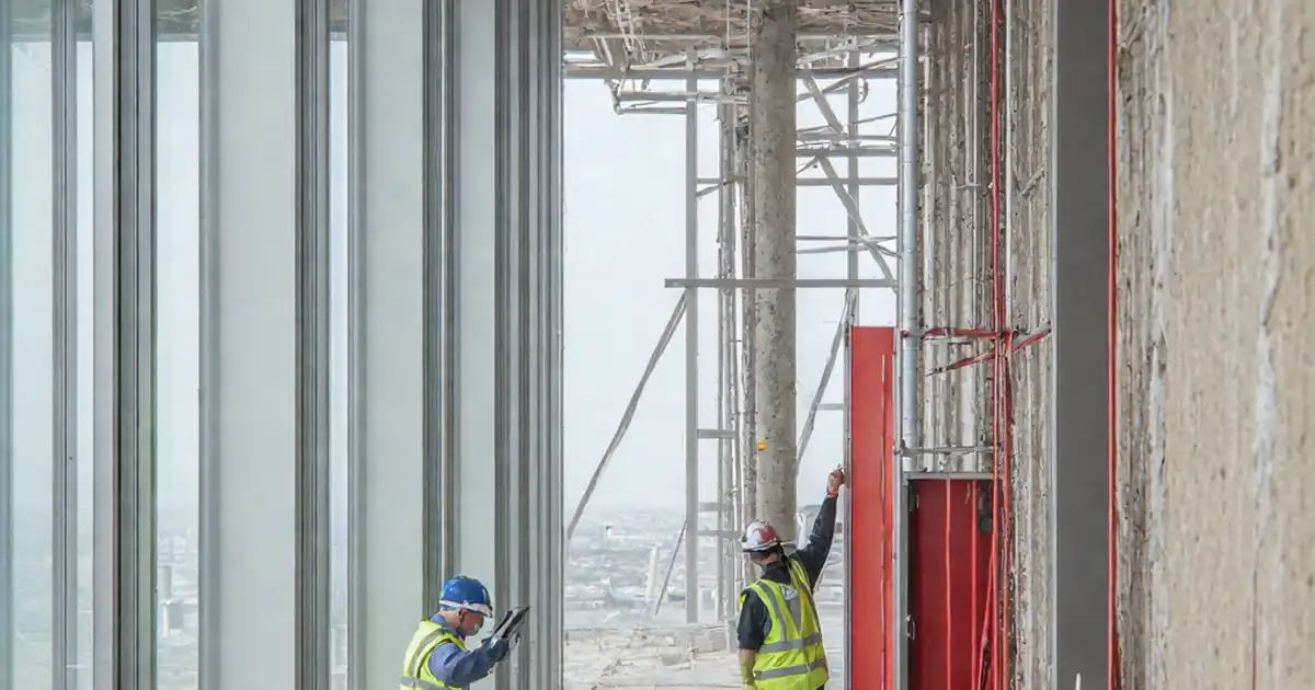
Define the specimen, boundaries, and isolation strategy
Clarity at the outset prevents costly retests. Begin by selecting the exact façade specimen—window, curtain wall bay, or mixed interface—and marking its boundary on drawings and on the elevation with non-residue tape. Confirm which adjacent joints and penetrations must be isolated so that measured leakage represents the specimen alone. Coordinate access to heads, corners, and interfaces; ensure platforms and tools reach all edges safely. Review the approved project specifications and authority requirements to confirm pressure steps, data capture intervals, and acceptance tolerances. Align testing hours with low interior disturbance to stabilize baselines. Finally, secure a make-good plan for removing temporary seals without damaging coatings or substrates. These preparations create a closed test loop, reducing background leakage and interpretation errors while making evidence capture straightforward and defensible in reviews.
- Mark and photograph the specimen boundary on drawings and elevation.
- Agree which adjacent joints to isolate and which to leave.
- Plan safe access to all edges, corners, heads, and sills.
- Confirm pressures, data intervals, and tolerances with stakeholders.
- Document a tested process for clean seal removal.
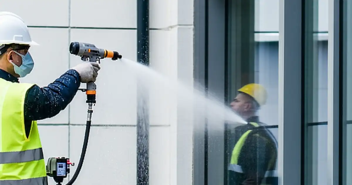
Apply reversible, traceable temporary sealing
Temporary sealing should prevent unintended air paths while avoiding damage. Use 150–200 µm polyethylene film, low-tack tapes, reusable vent covers, and backer rod to isolate non-test openings. Protect sensitive finishes with release paper, and always conduct a 24-hour patch test on discreet areas before full application. Tag masked weeps and vents so they are reinstated immediately after testing. Validate isolation effectiveness with smoke pencil sweeps and quick anemometer checks at sealed faces; you should see no smoke draw and velocities at or below 0.1 m/s. Keep a log of materials, lot numbers, and locations to make the process auditable. Remember: do not obstruct the specimen’s intended leakage path—seal only what the plan defines. This balance safeguards finishes, speeds removal, and preserves test integrity.
- Use low-tack, release-backed systems on sensitive substrates.
- Perform 24-hour adhesive transfer tests before full application.
- Tag and count each masked weep and vent for reinstatement.
- Verify isolation with smoke and anemometer readings.
- Record material lot numbers and installation locations.
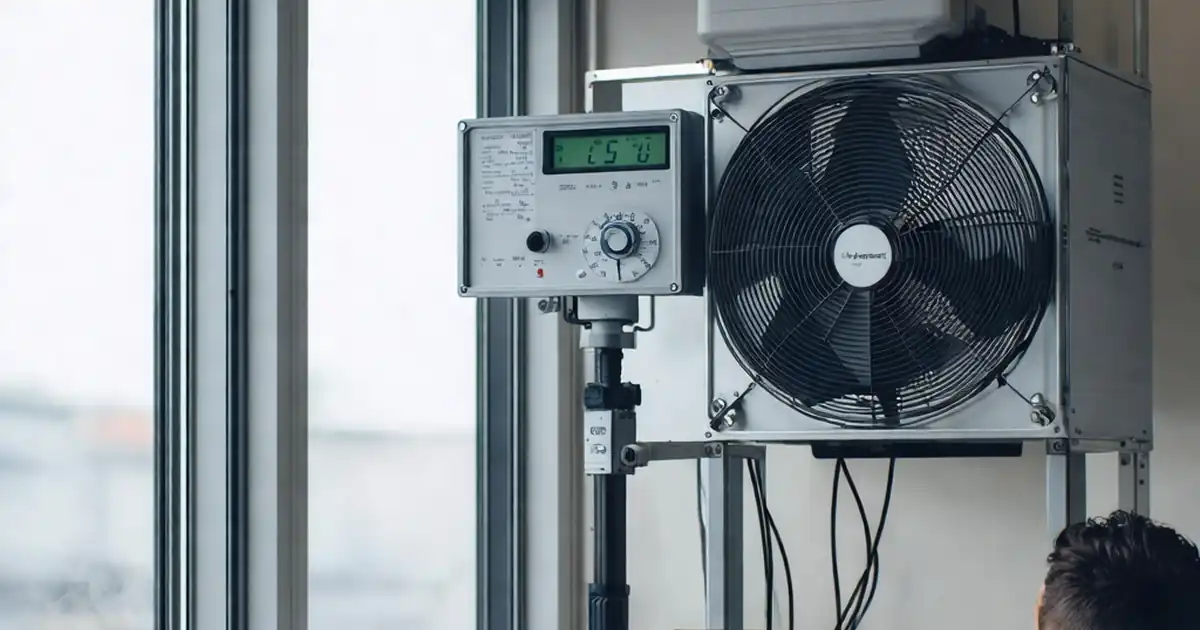
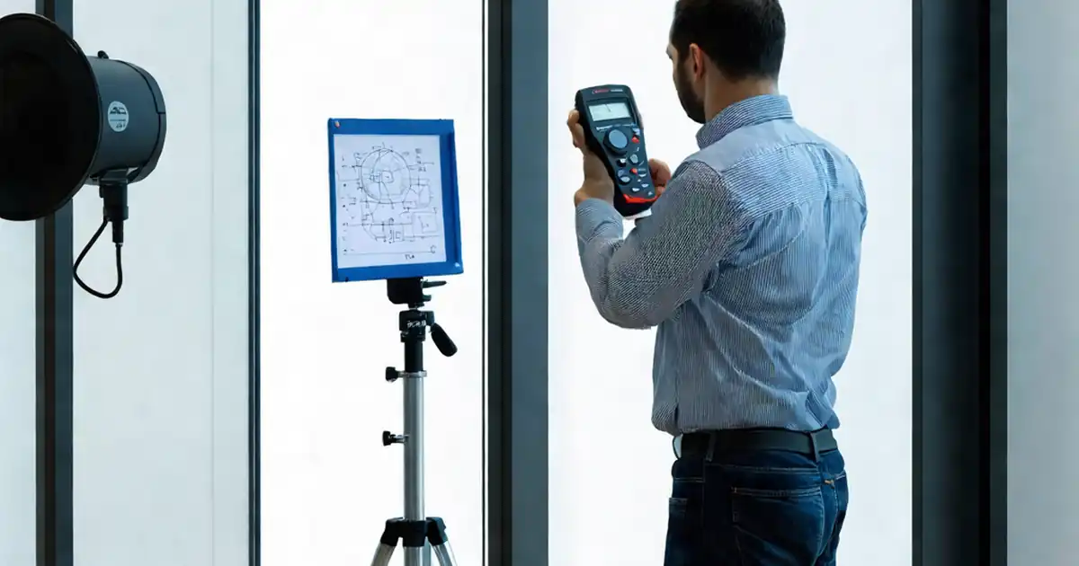
Stabilize instruments, environment, and safety controls
Reliable data depends on stable pressures and calibrated instruments. Zero the digital manometer to within ±0.3 Pa and leak-check the chamber or fan using a blank-off so system leakage stays below 5% of target flow. Place pressure taps at agreed heights with tidy, unkinked tubing, then establish a baseline: pressure should remain within ±2 Pa for at least 60 seconds. Confirm fan flow capacity exceeds your estimated leakage by at least 20% to avoid range changes mid-test. Check weather: average wind should be ≤ 6 m/s with temperature 5–35 °C and RH 30–80%. Establish exclusion zones and maintain operable egress while equipment runs. These steps minimize noise in the data, reduce retests, and protect people working around the façade during pressurization.
- Zero manometers and verify current calibration certificates.
- Leak-check chamber/fan; target < 5% system leakage.
- Hold baseline within ±2 Pa before starting test steps.
- Confirm wind, temperature, and RH within acceptable limits.
- Set barriers and preserve emergency egress routes.
How to use this checklist for façade air leakage readiness
- Preparation: Assemble low-tack tapes, polyethylene film (150–200 µm), backer rod, reusable vent covers, smoke pencil, anemometer, calibrated manometer, chamber/fan kit, measuring tools, PPE, and access equipment.
- Preparation: Review drawings and specifications; mark the specimen boundary on elevation; brief the team on isolation limits, safety, communication, and make-good procedures.
- Preparation: Confirm weather window, instrument calibration certificates, and equipment capacity; set up exclusion zones and verify egress routes remain operable.
- Using the Interactive Checklist: Start interactive mode, assign items to team members, tick completed tasks, and attach photos, readings, and documents to each step.
- Using the Interactive Checklist: Add comments to flag issues or clarifications, tag stakeholders, and generate interim exports to PDF/Excel for quick reviews.
- Sign-Off: When all readiness items are complete, capture digital signatures from the contractor, consultant, and client representatives; the system secures the record with a QR code.
- Sign-Off: Archive the final export in project folders, reference the specimen ID and date, and share a read-only link with the test team for on-site use.
Call to Action
- Start Checklist Tick off tasks, leave comments on items or the whole form, and export your completed report to PDF or Excel—with a built-in QR code for authenticity.
- Download Excel - Façade Air Leakage Readiness & Temporary Sealing
- Download PDF - Façade Air Leakage Readiness & Temporary Sealing
- View Image - Façade Air Leakage Readiness & Temporary Sealing
Cite & Embed
“Façade Air Leakage Readiness & Temporary Sealing by Quollnet”
with a link to
this source page.
FAQ
Question: What should be temporarily sealed for a façade air leakage test?
Question: What environmental conditions are acceptable before starting pressurization?
Question: Which materials are best for temporary sealing without damaging finishes?
Question: How do we prove readiness and avoid disputes later?
Related Articles
Broader reading and guidance connected to this checklist topic.


Related Checklists
Keep the workflow moving with nearby templates chosen from similar checklist content.