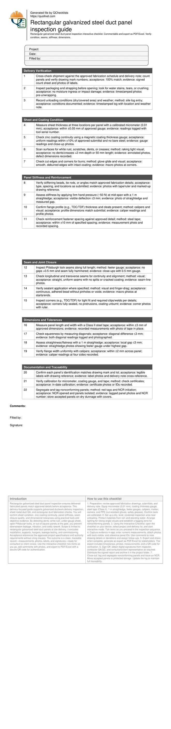
Rectangular Galvanized Steel Duct Panel Inspection
Definition: Rectangular galvanized steel duct panel inspection for site delivery verifies fabrication quality for QA/QC engineers, contractors, and consultants against approved drawings and specifications.
- Verify sheet condition, stiffness, seam closure, and dimensions on delivery.
- Prevent leaks, corrosion, and rework by catching fabrication nonconformities early.
- Measure with micrometer, gauges, and tape; document with photos and signatures.
- Interactive, commentable, export options with QR code verification.
Rectangular galvanized steel duct panel inspection ensures delivered fabricated panels match approved details before acceptance. This delivery-focused guide supports galvanized ductwork delivery inspection, sheet metal duct QA, and rectangular duct fabrication checks. You will confirm sheet condition, zinc coating continuity, panel stiffness, seam closure quality, and dimensional tolerances using practical tools and objective evidence. By detecting dents, white rust, under-gauge sheet, open Pittsburgh locks, or out-of-square panels at the gate, you prevent downstream leakage, vibration, and costly rework. Scope is limited to rectangular galvanized steel duct panels at site delivery; it excludes installation, supports, hangers, leakage testing, and commissioning. Acceptance references the approved project specifications and authority requirements without citing clauses. The outcome is a clean, traceable record—measurements, photos, labels, and signatures—ready for consultant or client review. Use the interactive checklist: tick items as you go, add comments with photos, and export to PDF/Excel with a secure QR code for authentication.
- Verify delivered rectangular galvanized steel duct panels against approved fabrication details the moment they arrive. Catch damage, under-gauge sheet, coating defects, open seams, and dimensional errors before installation. Objective measurements, photos, and signatures create a defensible acceptance record for stakeholders.
- Interactive online checklist with tick, comment, and export features secured by QR code.
- Structured acceptance criteria cover sheet thickness, zinc coating uniformity, panel stiffness, seam integrity, and dimensional tolerances. Clear tools and methods—micrometers, coating gauges, straightedges, feeler gauges, and steel tapes—guide inspectors and foremen to consistent, repeatable outcomes across deliveries and lots.
- Robust traceability ties each panel to submittals, coil or lot IDs, and delivery notes. Nonconforming material is immediately tagged and segregated, preventing accidental installation. Approved panels are protected and stored correctly, reducing corrosion risk and preserving finish quality for subsequent installation stages.
Delivery Verification
Sheet and Coating Condition
Panel Stiffness and Reinforcement
Seam and Joint Closure
Dimensions and Tolerances
Documentation and Traceability
Sheet and Coating Condition on Delivery
Start with the substrate: the galvanized sheet must match the approved fabrication details. Use a calibrated micrometer to measure thickness at multiple points on each panel, avoiding edges and beads. Readings should be within ±0.05 mm of the approved gauge. Next, verify zinc coating continuity and relative thickness using a magnetic gauge—values should be consistent with the approved submittal within ±10% and show no exposed base steel. Under angled light, scan for dents, creases, transit scratches, and white rust. Minor superficial marks can be accepted if they do not breach the coating; deeper dents and coating loss should trigger nonconformance. Run a gloved hand along cut edges to detect burrs that could tear seals or injure installers. Document all conditions with close-up photos and tie observations to panel IDs and delivery notes for traceability. Early rejection of compromised panels prevents corrosion, air leaks, and costly rework downstream.
- Measure thickness with micrometer; target within ±0.05 mm of submittal.
- Check coating with magnetic gauge; no bare steel or thin spots.
- Reject dents or creases exceeding 2 mm depth or 50 mm length.
- Edges must be smooth and deburred; no sharp burrs or snags.
- Photograph defects and link to panel IDs and delivery notes.
Panel Stiffness and Reinforcement Details
Panel rigidity prevents flutter, noise, and joint failure. Confirm stiffening beads, tie rods, angles, and flanges exactly match the approved shop drawings. Where feasible, perform a simple field deflection check: place a 1 m straightedge across the panel face and apply firm hand pressure (~50 N) at mid-span; a deflection gap no greater than 3 mm is typically acceptable for delivered panels unless the project specifies otherwise. Verify that flange profiles (e.g., TDC/TDF) and cleats conform to the submitted profiles, and check reinforcement fastener spacing with a steel tape—variations should remain within ±10 mm of specified spacing. Ensure the galvanizing is intact at reinforcement interfaces and corners. Capture photos with measurement tools in frame, annotate any deviations, and reference drawing details in comments so corrective actions are unambiguous and trackable.
- Stiffening elements match approved drawings and locations.
- Deflection under hand load shows ≤3 mm gap beneath straightedge.
- Flange profiles and cleats conform to submitted dimensions.
- Fastener spacing within ±10 mm of specified intervals.
- No coating damage at beads, tie rods, or angles.
Seam Closure and Dimensional Accuracy
Air-tightness and fit-up depend on seam integrity and precise dimensions. Inspect Pittsburgh or snap-lock seams along their full length; use a 0.5 mm feeler gauge to confirm there are no open gaps and that hammering is uniform without splits or cracked coating. Where sealant is specified, check for a continuous bead without pinholes, voids, or skips. Measure panel length and width with a Class II steel tape; typical acceptance is within ±3 mm of approved sizes. Check squareness by comparing diagonals—differences should not exceed 3 mm. Finally, confirm straightness and flatness using a 1 m straightedge; any local gap should remain ≤3 mm. Verify flange width uniformity with calipers to ±2 mm. Record all values, capture photos showing tools in use, and flag outliers immediately for segregation and nonconformance reporting.
- Feeler gauge confirms no seam gaps greater than 0.5 mm.
- Sealant, where required, is continuous and well-adhered.
- Length/width within ±3 mm; diagonal difference ≤3 mm.
- Straightedge gap ≤3 mm; flange width within ±2 mm.
- Photograph measurements with tools visible for verification.
How to Use This Interactive Inspection Checklist
- Preparation: review approved fabrication drawings, submittals, and delivery note. Equip micrometer (0.01 mm), coating thickness gauge, steel tape (Class II), 1 m straightedge, feeler gauges, calipers, marker, camera, and PPE (cut-resistant gloves, safety glasses). Confirm tools are calibrated.
- Set up a dry, level, cordoned inspection area near unloading. Protect materials from rain and standing water. Arrange lighting for raking-angle visuals and establish a tagging zone for nonconforming panels.
- Using the Interactive Checklist: open the checklist on your device, select project and delivery lot, and start interactive mode. Tick items as you proceed in the inspection sequence.
- Capture evidence in-app: enter numeric measurements, attach photos with tools visible, and reference panel IDs. Use comments to note drawing details or deviations and assign follow-ups.
- Export and share: when complete, generate an export as PDF/Excel for stakeholders. The export includes timestamps, photos, measurements, and a QR code for verification.
- Sign-Off: obtain digital signatures from inspector, contractor QA/QC, and consultant/client representative as required. Distribute the signed report and archive it in the project folder.
- Close-out: tag and segregate nonconforming panels and issue an NCR. Move accepted panels to protected storage. Update the log to maintain full traceability.
Call to Action
- Start Checklist Tick off tasks, leave comments on items or the whole form, and export your completed report to PDF or Excel—with a built-in QR code for authenticity.
- Download Excel - Rectangular Duct Panel Delivery Inspection
- Download PDF - Rectangular Duct Panel Delivery Inspection
- View Image - Rectangular Duct Panel Delivery Inspection
Cite & Embed
“Rectangular Duct Panel Delivery Inspection by Quollnet”
with a link to
this source page.
FAQ
Question: What tolerances should I use for panel dimensions at delivery?
Question: How can I confirm seam closure without specialized lab equipment?
Question: What should I do if I find white rust on galvanized panels?
Question: How do I document tool calibration during the inspection?
Related Articles
Broader reading and guidance connected to this checklist topic.
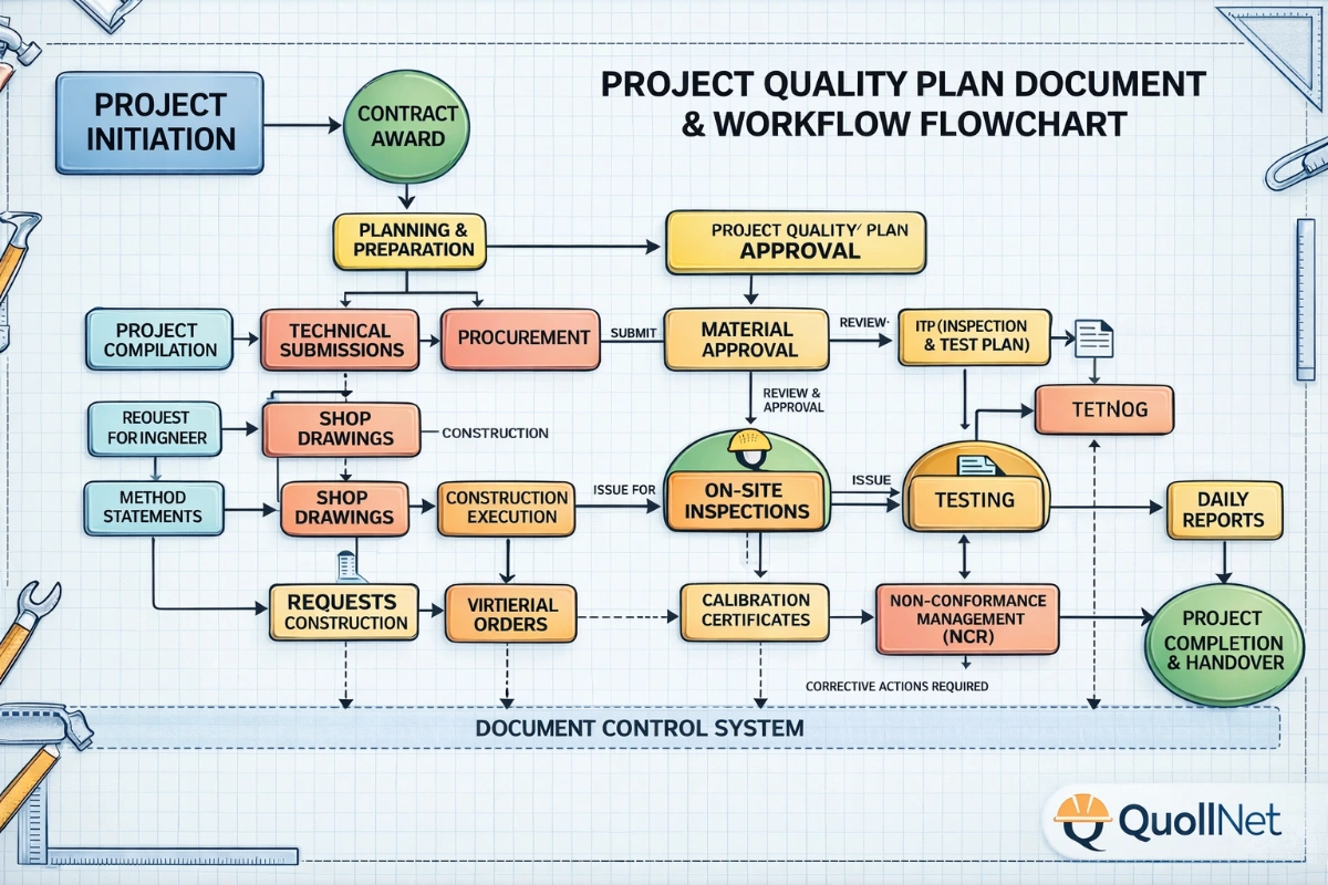

Open Ncrs At Taking-over / Dlp: What Happens At Handover And How To Escalate

3d Printed Concrete Defects: Visual Field Guide For Site Engineers
Related Checklists
Keep the workflow moving with nearby templates chosen from similar checklist content.