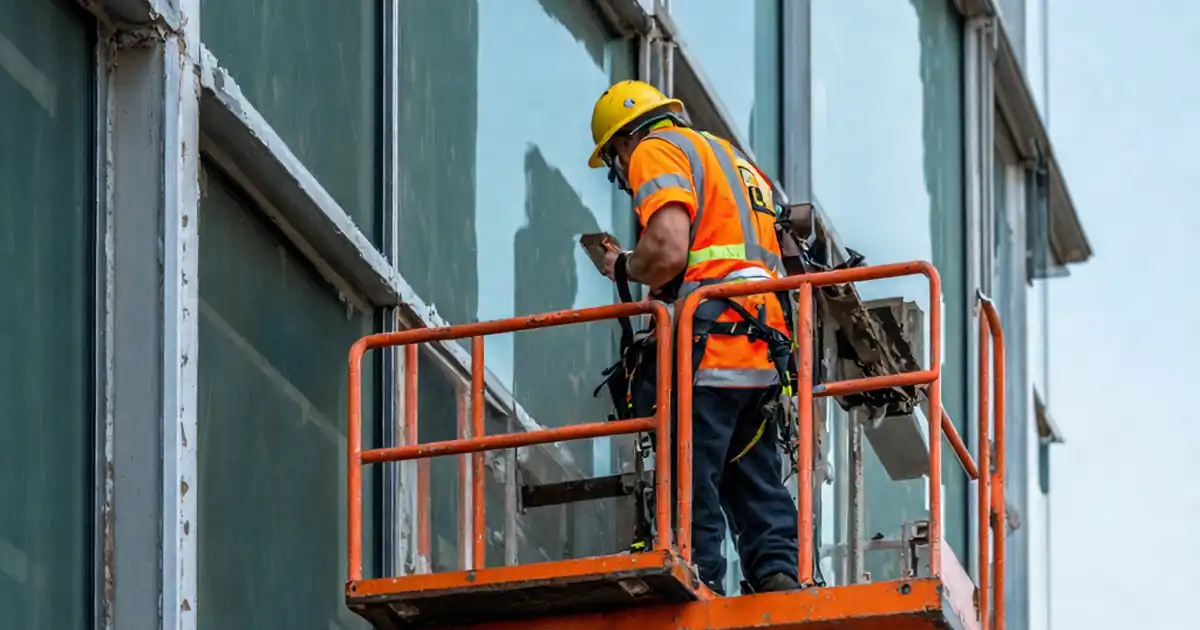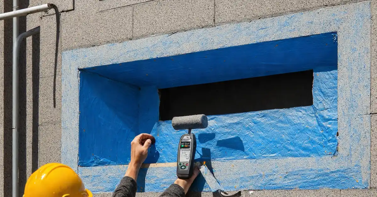
Inspect punched window perimeter sealant and waterproofing interface for exterior envelopes, guiding site engineers, QC managers, and installers through materials verification, installation quality, moisture control, and documentation.
- Verify WRB continuity, flashing laps, and sill drainage paths.
- Confirm sealant joint geometry, tooling, and material compatibility.
- Reduce leaks by sequencing work and checking environmental conditions.
- Interactive, commentable checklist with export and QR code verification.
The checklist
Documentation & Environmental Conditions
- Verify approved drawings, details, and manufacturer data sheets match the opening ID and site conditions.
- Record ambient/substrate temperature and RH using IR thermometer and hygrometer; accept within product limits (e.g., 5–40 °C, RH < 85%); attach time-stamped photos.
- Review forecast and install weather protection (tarp/tenting) so no rain contacts fresh sealant for 24 h; upload forecast screenshot and site photos.
- Measure substrate moisture with a meter; accept ≤ 15% or per manufacturer; log readings and photo of meter display.
Substrate & Opening Preparation
- Measure rough opening against drawings with a steel tape; accept ± 3 mm tolerance; record dimensions and include a photo with tape visible.
- Verify sill slopes outward using a digital level; accept 3–6° (≈1:20–1:10); photograph level reading.
- Inspect substrates for soundness and cleanliness; perform tape pull where needed; accept no dust, oil, laitance, or loose coatings; upload close-up photos.
- Confirm fastener/anchor penetrations are per design and sealed; accept no unplanned holes through WRB; provide annotated photos or RFI reference.
Waterproofing Interface & Flashings
- Install/inspect sill pan or liquid-applied pan; accept continuous coverage, upturn 25–50 mm, formed end dams; show roller/trowel marks and ruler in photos.
- Verify shingle-style WRB laps around opening; accept ≥ 100 mm vertical laps and ≥ 150 mm head overlaps; photograph each side.
- Inspect corner reinforcement patches (pre-formed or layered); accept full adhesion with no fishmouths or wrinkles; upload close-up photos.
- Check transition membrane bonding from wall WRB to frame/flange; pressure-roll; accept 65–100 mm laps and full contact; include roller-in-use photo.
- Seal all membrane terminations and penetrations at head and jambs with compatible sealant; accept continuous 6–10 mm fillet; provide photos.
Sealant Application & Tooling
- Confirm backer rod is closed-cell and 25–30% larger than joint width; measure with calipers; record product and lot number photo.
- Check joint width/depth using feeler gauge and spacers; accept width per design (typically 6–12 mm) and depth ≈ 1/2 width; attach measurements.
- Apply primer (if required) by brush/roller; verify uniform wet-film thickness with a gauge and correct flash-off; log WFT readings and time.
- Gun sealant in a continuous bead from bottom up; accept no voids, overlaps ≥ 25 mm at restarts; capture in-progress photos.
- Tool to a smooth, concave profile using a rounded spatula per manufacturer; verify two-sided adhesion (backer/bond breaker in place); upload close-ups.
- Record sealant product name, color, movement capability, expiration date, and lot; photograph labels and upload delivery tickets.
Verification, Testing & Records
- Protect fresh sealant with temporary shields/signage; accept no disturbance until tack-free/cured per datasheet; log cure start/finish and photos.
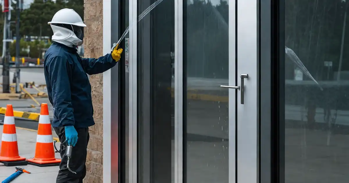
- Conduct controlled water spray test after cure per approved project specifications and authority requirements; 205–380 kPa for 5–10 min; accept no interior leaks; upload video/photos.
- Scan interior for moisture using infrared camera or moisture meter; accept readings at or below background; attach thermal images and meter photos.
- Confirm sill weeps/drain paths are clear using a probe; accept unobstructed flow to exterior; include before/after photos.
- Complete digital sign-off by installer, QC, and client; close NCRs or record corrective actions; export PDF/Excel with QR for archives.
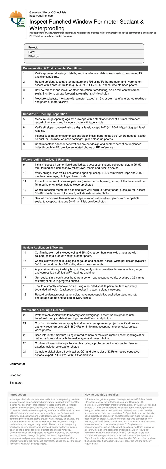
Preview the printable checklist
Preview page one below. Open the image or download the PDF for all pages.
At a glance
- Focuses on the window-to-wall interface, verifying WRB continuity, shingle-style laps, pan flashing geometry, and sealant joint design so the assembly sheds water, controls air, and allows joint movement without three-sided adhesion or premature failure.
- Builds robust evidence: capture substrate moisture and temperature readings, wet-film thickness for primers, lot numbers, photos of laps and corners, and curing records. The result is a defensible, time-stamped audit trail for quality and warranty submission.
- Reduces rework by sequencing activities and confirming conditions before application—clean, dry substrates; correct joint widths and backer rod sizing; compatible primers; and uninterrupted sealant beads tooled to a smooth, concave profile for optimal adhesion.
- Interactive online checklist with tick, comment, and export features secured by QR code.
How to Use This Interactive Checklist
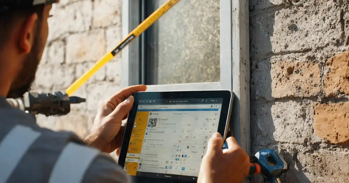
- Preparation: gather approved drawings, sealant/WRB data sheets, PPE, steel tape, calipers, feeler gauges, wet-film gauge, IR thermometer, hygrometer, moisture meter, digital level, roller/trowel, and camera.
- Verify site conditions: clean work zone, weather protection ready, materials acclimated, and tools calibrated with spare batteries and memory for photo documentation.
- Open the interactive checklist, select project and opening ID, and start inspection mode to tick items sequentially by group.
- Attach evidence: add time-stamped photos, readings, and label shots to each item; use comments to note locations, measurements, and responsible parties.
- Flag issues as nonconformances, assign actions with due dates, and track status until closure without altering completed evidence.
- Export results as PDF/Excel with QR authentication for field verification; share with stakeholders and upload to the project document control system.
- Sign-off: capture digital signatures from installer, QC, and client; archive the finalized report per approved project specifications and authority requirements.
Why the Perimeter Sealant–WRB Interface Matters
The punched window perimeter is where water and air most often bypass the façade. A robust interface depends on clean, dry substrates; correct shingle-style laps; formed pan flashing at the sill; and a sealant joint that adheres to two sides only. Compatibility between the sealant, primers, WRB, and transition membranes prevents softening, loss of adhesion, or staining. Acceptance cues include lap lengths that shed water, sill slopes to the exterior, and uniform primer wet-film thickness with complete flash-off before gunning. Tooling creates tight feathered edges and a concave profile for stress distribution. Documenting lot numbers, readings, and photos builds a defensible record for warranty and turnover. This checklist focuses strictly on the exterior perimeter interface—head, jambs, and sill—excluding glazing bead and interior finish work. Apply it during pre-install, in-progress, and post-cure checks, and coordinate with installers so sequencing preserves drainage paths and air barrier continuity at the window opening interface.
- Shingle-style laps shed water away from the opening.
- Two-sided adhesion avoids three-sided restraint and joint failure.
- Sill pan with end dams directs water to exterior.
- Primer flash-off prevents solvent entrapment under sealant.
- Document lot numbers and readings for traceability.
Common Failure Modes and Prevention
Frequent defects include fishmouths in membranes, reversed laps, missing end dams, and sealant bridging across backer rod (three-sided adhesion). These conditions trap water or concentrate movement, leading to cracks, leaks, and early debonding. Poor environmental control—cold, wet, or dusty substrates—also undermines adhesion. Prevent issues by verifying slopes, laps, and corner patches before setting the frame; sizing closed-cell backer rod 25–30% larger than the gap; and confirming joint geometry with feeler gauges before gunning. Tool the bead promptly to a smooth, concave profile, keeping bond breakers in place. After curing, perform a controlled water spray to confirm watertightness, then scan interiors with a moisture meter or infrared camera. Record observations with photos and time-stamped readings, and escalate nonconformances for timely correction per approved project specifications and authority requirements.
- Size backer rod 25–30% larger than joint width.
- Eliminate fishmouths and reverse laps at corners.
- Maintain clean, dry substrates within temperature limits.
- Tool promptly to a smooth, concave profile.
- Confirm weeps and drainage remain unobstructed.
Field Testing, Evidence, and Handover
Testing validates what visual inspection suggests. After the sealant reaches tack-free or full cure (per datasheet), conduct a controlled water spray test at the head, jambs, and sill while observers monitor interiors. No water should bypass the interface. Follow with infrared or moisture meter checks to verify dry conditions behind finishes. Capture evidence: readings, photos of laps and corners with rulers, wet-film thickness of primers, and product labels with lot numbers and expiry dates. Maintain a log that ties each opening ID to its documents and test outcomes. Protect fresh work with temporary shields and signage to avoid accidental contact or contamination. Conclude with a digital sign-off, distributing an exportable PDF/Excel report linked by QR for rapid field verification and archiving, per approved project specifications and authority requirements.
- Test only after specified cure time elapses.
- Target zero interior leakage during water spray.
- Archive time-stamped photos and readings by opening ID.
- Use QR-linked exports for quick field verification.