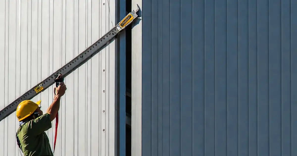
Inspect Aluminum Composite Panel Joints, Reveals & Sealant
Definition: Inspect aluminum composite panel joints, reveals, and sealant lines using this field-proven checklist for facade supervisors, capturing alignment, gap tolerances, and watertight, durable sealant performance.
- Verify joint layout, straightness, and uniform gap widths with tolerances.
- Confirm backer rods, primers, and sealant beads meet manufacturer requirements.
- Document photos, measurements, batches, and approvals for closeout records.
- Interactive, commentable checklist with export and QR code verification.
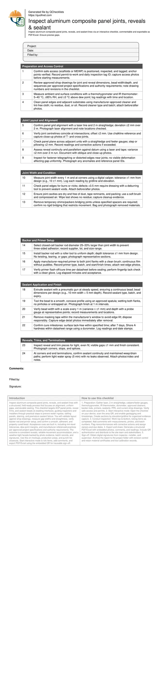
Inspect aluminum composite panel joints, reveals, and sealant lines with a structured, field-ready process that focuses on alignment, uniform gaps, and durable sealing. This checklist targets ACP panel joints, reveal trims, and sealant beads at cladding interfaces, guiding inspectors and installers through practical steps to prevent water ingress, rattling panels, staining, and premature sealant failure. You will validate layout against shop drawings, measure gap widths and straightness, verify backer rod and primer setup, and confirm a smooth, adherent, and properly cured bead. Acceptance cues are built in, including mm-level tolerances, dew point margins, and manufacturer-referenced practices per approved project specifications and authority requirements. The outcome is consistent reveals, reliable movement accommodation, and a weather-tight facade backed by photo evidence, batch records, and signatures. Use this on mockups, production areas, and punch-list closeouts. Start interactive mode to tick items, add comments, and export PDF/Excel using the embedded QR for traceable sign-off.
- Control risk of leaks, staining, and joint rattle by verifying grid alignment, straight reveals, and uniform widths with tight tolerances. Measure with laser lines, straightedges, and calipers, and record readings and photos at regular intervals to create objective evidence of compliance for each elevation and bay.
- Interactive online checklist with tick, comment, and export features secured by QR code. Use timestamps, tagged photos, tool calibrations, and material batch logs to create a defensible audit trail that satisfies stakeholders and accelerates closeout while reducing rework and warranty claims across multiple project zones.
- Improve sealant durability by confirming correct backer rod sizing, primer coverage, dew point margins, and a tooled concave profile. Track cure progress, hardness, and adhesion cues; remove masking within the specified window; and maintain weep paths at trims and terminations to preserve drainage and long-term weatherproofing performance.
Preparation and Access Control
Joint Layout and Alignment
Joint Width and Condition
Backer and Primer Setup
Sealant Application and Finish
Reveals, Trims, and Terminations
Control Alignment, Straightness, and Gap Uniformity
Accurate joint layout starts with the grid. Use a laser line to reference vertical and horizontal datums, then verify straightness with a 2 m straightedge. Keep cumulative deviation within 2 mm over 2 m to ensure reveals read cleanly across elevations. At intersections, centreline offsets should remain within 2 mm; larger misalignments telegraph visually and stress sealant. Measure gap widths at 1 m intervals and at corners using a digital caliper or feeler gauges, holding ±1 mm from the design width to maintain consistent movement capability. Record all measurements against gridlines for traceability. An on-site example: a stack misaligned by 4 mm over three levels was corrected by reseating clips and re-shimming, restoring uniform 10 ±1 mm joints. Capturing before/after photos and annotated readings accelerates approval and reduces punch-list churn.
- Straightness ≤2 mm over a 2 m straightedge.
- Intersection centreline offset ≤2 mm at T and cross-joints.
- Joint width tolerance typically ±1 mm from design.
- Log readings by gridline, elevation, and date.
Prepare Backer Rods and Primers for Reliable Adhesion
Sealant longevity depends on correct substrate preparation. Size closed-cell backer rods 25–33% larger than the joint to avoid three-sided adhesion and promote an hourglass/concave profile. Install rods uniformly with a roller tool; depth should match the designed sealant geometry within ±1 mm. Clean and dry joint flanks thoroughly; verify environmental conditions are 5–40 °C and ≤85% RH, with the surface at least 3 °C above dew point using a thermohygrometer and IR thermometer. Apply the specified primer as a continuous film and allow flash-off per the datasheet. Record primer and backer rod batch numbers and times. These steps reduce cohesive failure and edge peeling. Field experience shows that skipping primer on coil-coated ACP faces often leads to early debonding, especially on sun-exposed elevations.
- Backer rod 25–33% oversize to joint width.
- Depth uniformity within ±1 mm of design.
- Surface ≥3 °C above dew point before priming.
- Primer continuity; observe flash-off window.
Apply and Finish Sealant Beads for Durable Weatherproofing
Dispense sealant with a pneumatic gun at steady speed, maintaining continuous contact with both flanks. Tool immediately using an approved spatula to achieve a smooth, concave profile free of pinholes, voids, or smears. Verify bead width every 1 m, holding variance within ±1 mm; check depth with a probe gauge at representative points. Remove masking tape within the manufacturer’s window to avoid tearing or raised edges. Track cure: the surface should be tack-free within the stated time, and Shore A hardness after seven days should align with the datasheet. Maintain weep paths at trims and terminations; never seal across intended drainage. Common defects include slumping, trapped air, and primer skip—each is preventable by timing, tooling, and environmental control.
- Continuous bead, concave profile, no pinholes.
- Width variance ≤ ±1 mm; verify depth by probe.
- Remove masking within the specified window.
- Confirm tack-free and Shore A hardness milestones.
How to Use This Interactive ACP Joint & Sealant Checklist
- Preparation: Gather laser, 2 m straightedge, calipers/feeler gauges, thermohygrometer, IR thermometer, durometer, approved cleaners, backer rods, primers, sealants, PPE, and current shop drawings. Verify safe access and permits.
- Start interactive mode: Open the checklist on your device, scan the area QR, and enable geotagging and timestamps. Create sections by elevation/gridline for organized evidence capture.
- Conduct inspection: Work top-to-bottom, ticking items as completed. Add comments with measurements, photos, and batch numbers. Flag nonconformances with corrective actions and assign owners and due dates.
- Export and share: Generate a structured PDF/Excel with embedded photos, comments, and readings. Include QR authentication and distribute to the site team and stakeholders.
- Sign-off: Obtain digital signatures from inspector, installer, and supervisor. Archive the report to the project folder with revision control and retain material certificates and tool calibration records.
Call to Action
- Start Checklist Tick off tasks, leave comments on items or the whole form, and export your completed report to PDF or Excel—with a built-in QR code for authenticity.
- Download Excel - ACP Joint, Reveal, and Sealant Inspection
- Download PDF - ACP Joint, Reveal, and Sealant Inspection
- View Image - ACP Joint, Reveal, and Sealant Inspection
Cite & Embed
“ACP Joint, Reveal, and Sealant Inspection by Quollnet”
with a link to
this source page.
FAQ
Question: What joint width tolerance should I apply for aluminum composite panel joints?
Question: Do I need primer before applying sealant to ACP edges and trims?
Question: How do I handle temperature, humidity, and dew point during sealant work?
Question: What evidence should I capture to close out the joint and sealant inspection?
Related Articles
Broader reading and guidance connected to this checklist topic.


Master Construction Project Cashflow With Cashflowpot

Related Checklists
Keep the workflow moving with nearby templates chosen from similar checklist content.