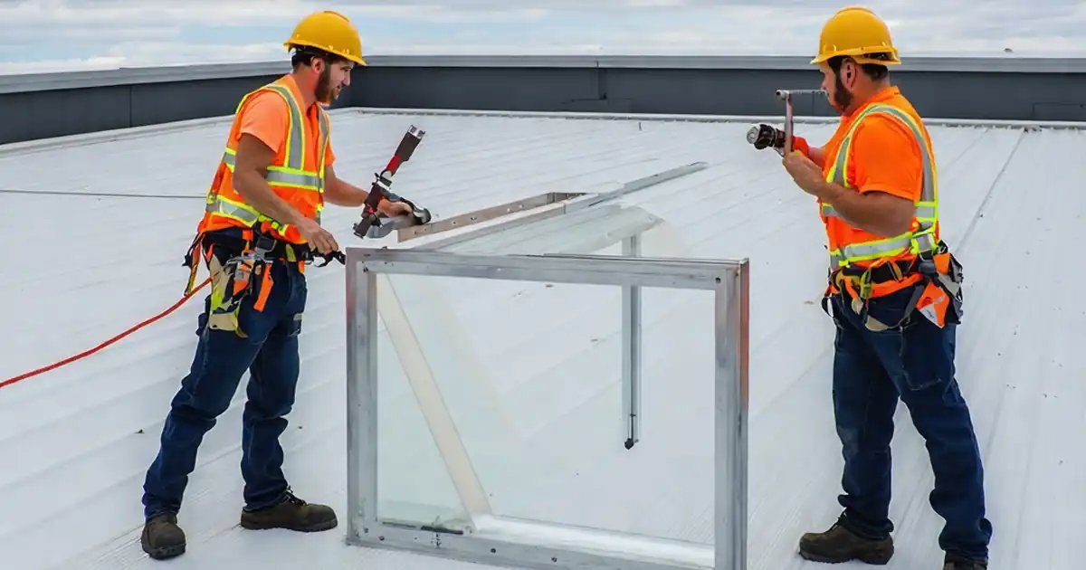
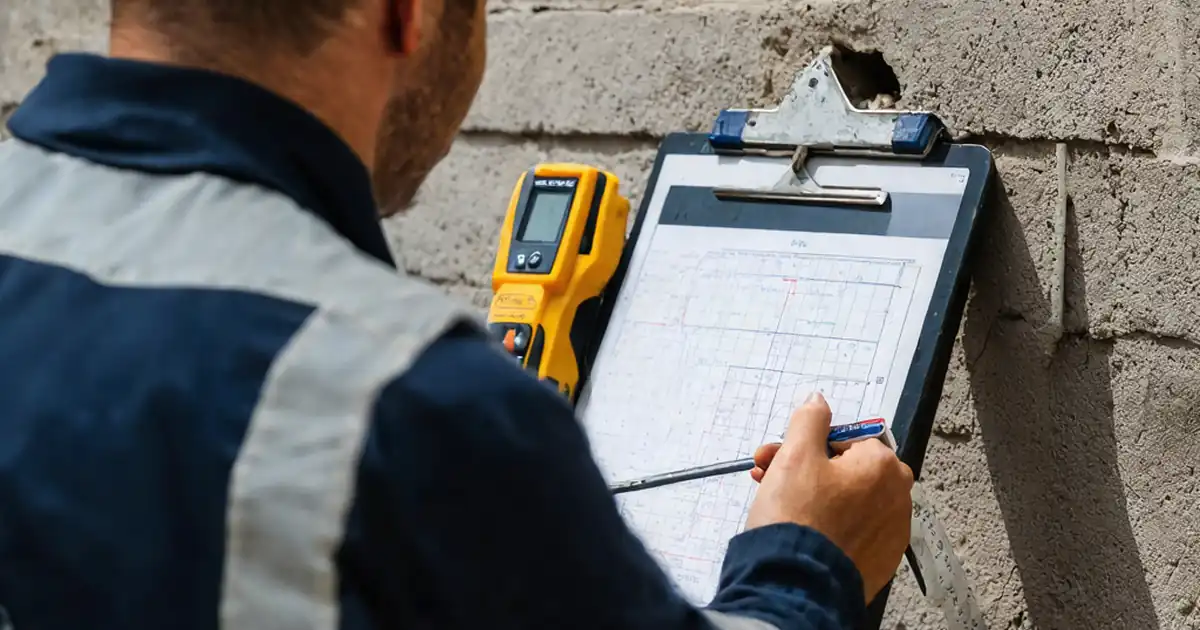
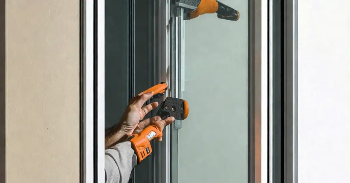
Punched Window Frame Alignment and Fixing Inspection Checklist
Definition: Inspect punched window frame installation for alignment and fixing is a site-ready checklist for contractors, inspectors, and facade coordinators to verify plumb, level, squareness, anchorage, sealant gaps, and documentation.
- Confirms plumb, level, squareness, and uniform perimeter gaps quickly.
- Verifies anchor type, spacing, torque, and shim bearing conditions.
- Captures photos, batch numbers, and approvals for traceable compliance.
- Interactive, commentable checklist with export to PDF/Excel and QR code.
Inspect punched window frame installation for alignment and fixing is essential to ensure every framed opening sits plumb, level, square, and securely anchored. This window alignment inspection targets installed punched frames in masonry or concrete walls, focusing on frame alignment and fixing verification rather than glazing or operable hardware. By standardizing plumb and level checks, diagonal measurement for squareness, anchor and fastener control, and perimeter joint sizing, the process reduces air and water leakage risk, prevents frame distortion, and protects finishes. You will confirm anchor type and torque, shim bearing, sill fall for drainage, backer rod and sealant setup, and proper air/water barrier tie-ins per approved project specifications and authority requirements. Outcomes include durable performance, fewer callbacks, and robust photographic evidence ready for handover. Use this interactive tool to tick each requirement, add field comments, attach photos, and export your record as PDF/Excel—accessed and verified via a secure project QR code.
- This checklist drives consistent, measurable control of punched window frame alignment and fixing. It defines practical field methods—laser, digital level, torque wrench, straightedge—and sets acceptance cues for plumb, level, squareness, gap uniformity, and drainage, preventing binding sashes, leaks, and facade misalignment while capturing photos and measurements.
- It enforces anchor and shim discipline: correct type, spacing, torque, and full-bearing shims prevent frame distortion and anchor creep. Joint design is validated with correctly sized backer rod, clean sealant beads, and verified weeps. Air and water barrier tie-ins are documented for a continuous enclosure line at each opening.
- Interactive online checklist with tick, comment, and export features secured by QR code.
- A complete audit trail links frame IDs, dates, installer/inspector names, torque readings, batch numbers, and as-built photos. This creates traceable compliance with approved project specifications and authority requirements, easing handover and warranty closeout while accelerating punch-list resolution and reducing costly rework on the facade.
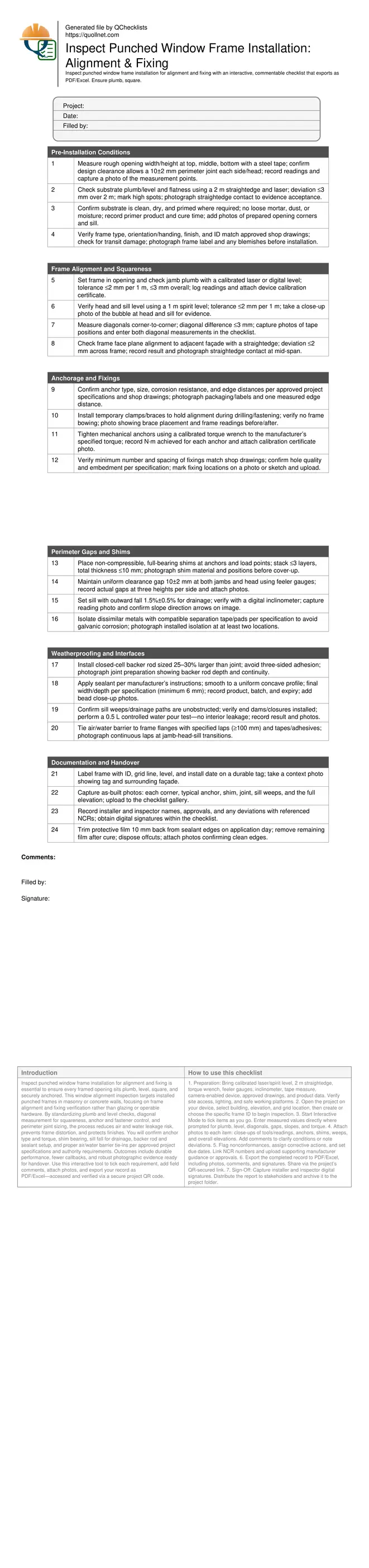
Pre-Installation Conditions
Frame Alignment and Squareness
Anchorage and Fixings
Perimeter Gaps and Shims
Weatherproofing and Interfaces
Documentation and Handover
Getting Plumb, Level, and Square—What to Measure and Why
Accurate frame alignment underpins airtightness, watertightness, and long service life. Start by confirming the rough opening allows the designed joint size, then set the frame with laser or spirit level to meet plumb/level tolerances (≤2 mm per metre, ≤3 mm overall). Check squareness by measuring diagonals; a difference ≤3 mm ensures equal load paths and clean reveals. Finally, verify the frame’s face plane against the wall so trims and sealant track neatly. On real jobs, subtle twists from uneven shims or overtightened anchors can pull a jamb off-plumb, causing sticky operation and early sealant failure. Use non-compressible shims at load points, recheck after each fixing, and document every reading with photos. Consistent measurement, immediate adjustments, and evidence capture eliminate guesswork and defend against future disputes at handover.
- Confirm opening allows the designed perimeter joint.
- Measure plumb, level, and diagonals before final tightening.
- Use non-compressible shims at anchors and load points.
- Recheck alignment after each fixing and photograph readings.
- Keep evidence tied to frame ID and location.
Anchorage That Holds Without Distorting the Frame
Fixings must resist loads while preserving geometry. Select anchors per approved project specifications and manufacturer guidance, matching the substrate (concrete, CMU, or steel). Control edge distances and embedment to prevent breakout or pull-out. Torque is critical: under-torque risks loosening; over-torque can bow the frame and pinch glazing clearances. Brace the frame before drilling, use sharp bits, and clear dust to reach full embedment. After tightening, recheck plumb, level, and diagonal measurements. In practice, a single over-torqued head fixing can introduce a 3 mm diagonal shift—enough to telegraph in trims and cause sash bind later. Record anchor type, spacing, torque values (N·m), and tool calibration dates; photograph representative anchors and labels. This gives a verifiable trail for quality audits, reduces rework, and assures long-term performance under wind and thermal cycling.
- Match anchor type to substrate and specification.
- Control edge distances and embedment depth.
- Tighten to manufacturer torque with a calibrated wrench.
- Recheck geometry after every tightening sequence.
- Photograph labels, anchors, and torque readings.
Perimeter Joints, Sill Drainage, and Barrier Tie-Ins
Correct joint design ensures durable seals. Maintain a uniform 10±2 mm perimeter gap for a properly sized closed-cell backer rod (25–30% larger than the joint). Apply sealant to a clean, primed surface and tool to a smooth concave profile, avoiding three-sided adhesion. At sills, build outward fall (about 1.5%) and keep weep paths clear with end dams or closures. Perform a simple 0.5 L water pour to confirm no interior leakage. Integrate air and water barriers to the frame with continuous 100 mm laps and compatible tapes or adhesives, ensuring corners are shingled. Field photos of each step—backer rod, bead, weeps, and membrane laps—prove continuity and workmanship. These measures prevent water ingress, reduce drafts, and stabilize thermal performance while presenting consistent, inspectable joints across the elevation.
- Keep perimeter gap uniform for correct backer rod sizing.
- Tool sealant to a smooth, concave profile.
- Provide sill fall and clear weeps for drainage.
- Tie barriers with 100 mm laps and compatible tapes.
- Photograph each interface before concealment.
How to Use This Interactive Inspection Checklist
- Preparation: Bring calibrated laser/spirit level, 2 m straightedge, torque wrench, feeler gauges, inclinometer, tape measure, camera-enabled device, approved drawings, and product data. Verify site access, lighting, and safe working platforms.
- Open the project on your device, select building, elevation, and grid location, then create or choose the specific frame ID to begin inspection.
- Start Interactive Mode to tick items as you go. Enter measured values directly where prompted for plumb, level, diagonals, gaps, slopes, and torque.
- Attach photos to each item: close-ups of tools/readings, anchors, shims, weeps, and overall elevations. Add comments to clarify conditions or note deviations.
- Flag nonconformances, assign corrective actions, and set due dates. Link NCR numbers and upload supporting manufacturer guidance or approvals.
- Export the completed record to PDF/Excel, including photos, comments, and signatures. Share via the project’s QR-secured link.
- Sign-Off: Capture installer and inspector digital signatures. Distribute the report to stakeholders and archive it to the project folder.
Call to Action
- Start Checklist Tick off tasks, leave comments on items or the whole form, and export your completed report to PDF or Excel—with a built-in QR code for authenticity.
- Download Excel - Punched Window Frame Alignment & Fixing Inspection
- Download PDF - Punched Window Frame Alignment & Fixing Inspection
- View Image - Punched Window Frame Alignment & Fixing Inspection
Cite & Embed
“Punched Window Frame Alignment & Fixing Inspection by Quollnet”
with a link to
this source page.

FAQ
Question: What are acceptable tolerances for plumb, level, and squareness on punched window frames?
Question: How should I verify anchor performance without over‑tightening and distorting the frame?
Question: What joint size and sealant setup work best around punched frames?
Question: How do I prove drainage and barrier continuity at each opening?
Related Articles
Broader reading and guidance connected to this checklist topic.

3d Printed Concrete Qa/qc: Inspection, Process Control & Acceptance


Related Checklists
Keep the workflow moving with nearby templates chosen from similar checklist content.